
Ebyte LoRa E22 device for Arduino, esp32 or esp8266: library – 2
LoRa or Long Range wireless data telemetry is a technology pioneered by Semtech that operates at a lower frequency than NRF24L01 (433 MHz, 868 MHz, or 916 MHz against 2.4 GHz for the NRF24L01) but at thrice the distance (from 4000m to 10000m).
I created a library to manage EBYTE E22 based on the Semtech SX1268 series of LoRa devices, a very powerful, simple, and cheap device.
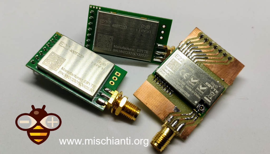
You can find here AliExpress (433MHz 5.5Km) - AliExpress (433MHz 10Km) - AliExpress (868MHz 915Mhz 5.5Km) - AliExpress (868MHz 915Mhz 10Km)
Library
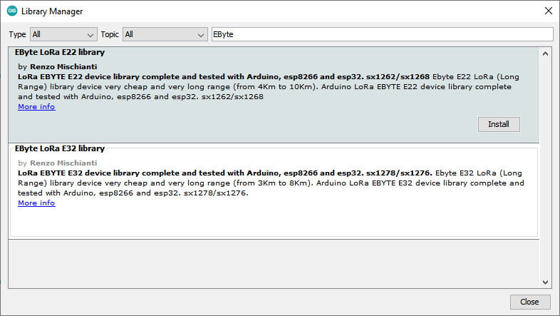
You can find my library here.
And It’s available on Arduino IDE library manager.
To download.
Click the DOWNLOADS button in the top right corner, rename the uncompressed folder LoRa_E22.
Check that the LoRa_E22 folder contains LoRa_E22.cpp and LoRa_E22.h.
Place the LoRa_E22 library folder your /libraries/ folder.
You may need to create the libraries subfolder if its your first library.
Restart the IDE.
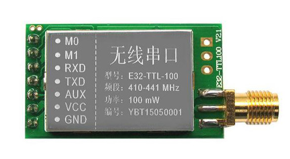
Pinout
| Pin No. | Pin item | Pin direction | Pin application |
|---|---|---|---|
| 1 | M0 | Input(weak pull-up) | Work with M1 & decide the four operating modes.Floating is not allowed, can be ground. |
| 2 | M1 | Input(weak pull-up) | Work with M0 & decide the four operating modes.Floating is not allowed, can be ground. |
| 3 | RXD | Input | TTL UART inputs, connects to external (MCU, PC) TXD outputpin. Can be configured as open-drain or pull-up input. |
| 4 | TXD | Output | TTL UART outputs, connects to external RXD (MCU, PC) inputpin. Can be configured as open-drain or push-pull output |
5 | AUX | Output | Per indicare lo stato di funzionamento del modulo e riattivare l’MCU esterno. Durante la procedura di inizializzazione di autocontrollo, il pin emette una bassa tensione. Può essere configurato come uscita open-drain o output push-pull (è consentito non metterlo a terra, ma se hai problemi, ad esempio ti si freeze il dispositivo è preferibile mettere una restistenza di pull-up da 4.7k o meglio collegarlo al dispositivo). |
| 6 | VCC | Power supply 2.3V~5.5V DC | |
| 7 | GND | Ground |
As you can see you can set various modes via M0 and M1 pins.
| Mode | M1 | M0 | Explanation |
|---|---|---|---|
| Normal | 0 | 0 | UART and wireless channel are open, transparent transmission is on (Supports configuration over air via special command) |
| WOR Mode | 0 | 1 | Can be defined as WOR transmitter and WOR receiver |
| Configuration mode | 1 | 0 | Users can access the register through the serial port to control the working state of the module |
| Deep sleep mode | 1 | 1 | Sleep mode |
There are some pins that can be use in a static way, but If you connect It to the microcontroller and configure they in the library you gain in performance and you can control all mode via software, but we are going to explain better next.
Fully connected schema
As I already say It’s not important to connect all pin to the output of microcontroller, you can put M0 and M1 pins to HIGH or LOW to get desidered configuration, and if you don’t connect AUX the library set a reasonable delay to be sure that the operation is complete (If you have trouble like freeze device, you must put a pull-up 4.7k resistor or better connect to the device. ).
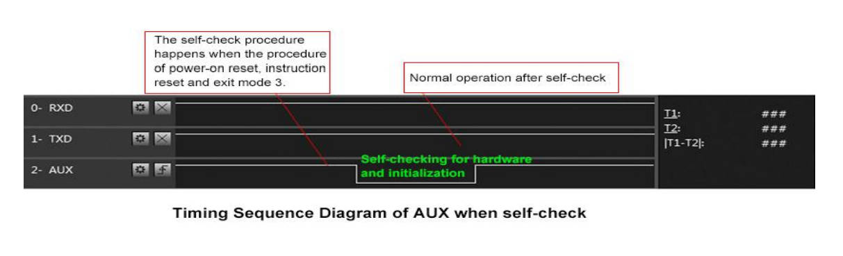
AUX pin
When transmitting data can be used to wake up external MCU and return HIGH on data transfer finish.
When receiving AUX going LOW and return HIGH when buffer is empty.
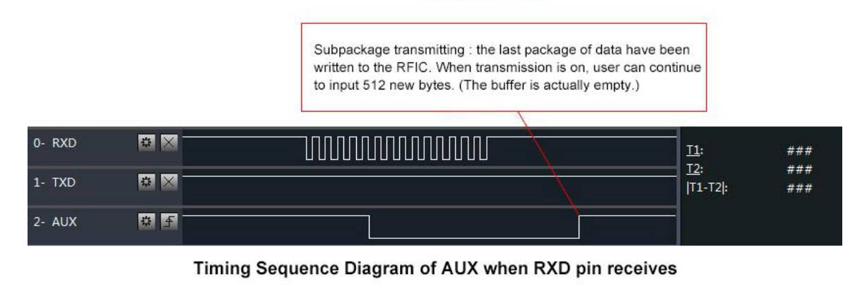
It’s also used for self checking to restore normal operation (on power-on and sleep/program mode).
esp8266
esp8266 connection schema is more simple because It work at the same voltage of logical communications (3.3v).
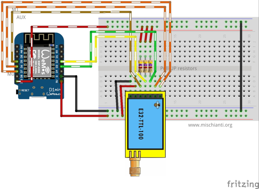
It’s important to add pull-up resistor (4,7Kohm) to get good stability.
| E22 | esp8266 |
|---|---|
| M0 | D7 |
| M1 | D6 |
| TX | PIN D2 (PullUP 4,7KΩ) |
| RX | PIN D3 (PullUP 4,7KΩ) |
| AUX | PIN D5 (PullUP 4,7KΩ) |
| VCC | 5V (but work with less power in 3.3v) |
| GND | GND |
esp32
Similar connection schema for esp32, but for RX and TX we use RX2 and TX2, because by default esp32 doesn’t have SoftwareSerial but have 3 Serial.
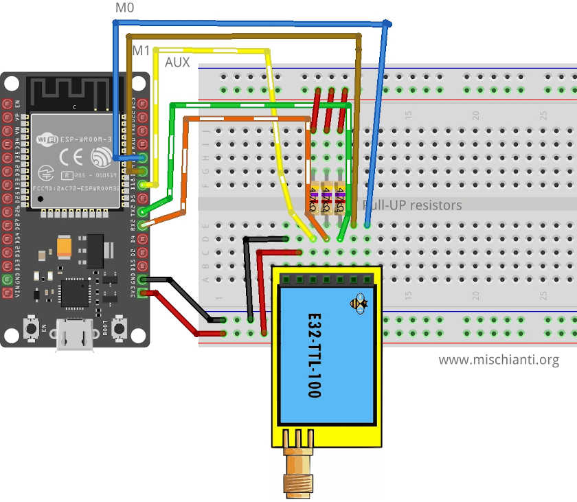
| E22 | esp32 |
|---|---|
| M0 | D21 |
| M1 | D19 |
| TX | PIN RX2 (PullUP 4,7KΩ) |
| RX | PIN TX3 (PullUP 4,7KΩ) |
| AUX | PIN D18 (PullUP 4,7KΩ) |
| VCC | 5V (but work with less power in 3.3v) |
| GND | GND |
Arduino
Arduino working voltage is 5v, so we need to add a voltage divider on RX pin M0 and M1 of LoRa module to prevent damage, you can get more information here Voltage divider: calculator and application.
You can use a 2Kohm resistor to GND and 1Kohm from signal than put together on RX.
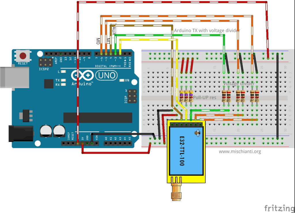
| M0 | 7 (voltage divider) |
| M1 | 6 (voltage divider) |
| TX | PIN 2 (PullUP 4,7KΩ) |
| RX | PIN 3 (PullUP 4,7KΩ & Voltage divider) |
| AUX | PIN 5 (PullUP 4,7KΩ) |
| VCC | 5V |
| GND | GND |
Arduino MKR WiFi 1010
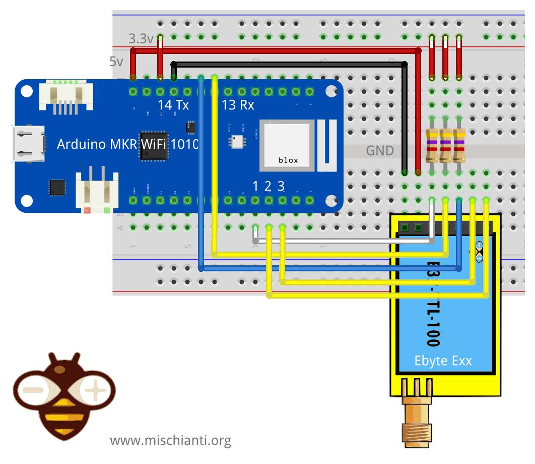
| M0 | 2 (voltage divider) |
| M1 | 3 (voltage divider) |
| TX | PIN 14 Tx (PullUP 4,7KΩ) |
| RX | PIN 13 Rx (PullUP 4,7KΩ) |
| AUX | PIN 1 (PullUP 4,7KΩ) |
| VCC | 5V |
| GND | GND |
Constructor
I made a set of quite numerous constructors, because we can have more options and situations to manage.
		LoRa_E22(byte txE22pin, byte rxE22pin, UART_BPS_RATE bpsRate = UART_BPS_RATE_9600);
		LoRa_E22(byte txE22pin, byte rxE22pin, byte auxPin, UART_BPS_RATE bpsRate = UART_BPS_RATE_9600);
		LoRa_E22(byte txE22pin, byte rxE22pin, byte auxPin, byte m0Pin, byte m1Pin, UART_BPS_RATE bpsRate = UART_BPS_RATE_9600);
First set of constructor are create to delegate the manage of Serial and other pins to the library.
txE22pinandrxE22pinis the pin to connect to UART and they are mandatory.auxPinis a pin that check the operation, transmission and receiving status (we are going to explain better next), that pin It isn’t mandatory, if you don’t set It I apply a delay to permit the operation to complete itself (with latency, if you have trouble, like freeze device, you must put a pull-up 4.7k resistor or better connect to the device ).m0pinandm1Pinare the pins to change operation MODE (see the table upper), I think this pins in “production” are going to connect directly HIGH or LOW, but for test they are usefully to be managed by the library.bpsRateis the boudrate of SoftwareSerial normally is 9600 (the only baud rate in programmin/sleep mode)
A simple example is
#include "LoRa_E22.h"

LoRa_E32 e22ttl100(2, 3);  // e22 TX e22 RX
// LoRa_E32 e32ttl100(2, 3, 5, 6, 7);  // e22 TX e22 RX
We can use directly a SoftwareSerial with another constructor
		LoRa_E22(HardwareSerial* serial, UART_BPS_RATE bpsRate = UART_BPS_RATE_9600);
		LoRa_E22(HardwareSerial* serial, byte auxPin, UART_BPS_RATE bpsRate = UART_BPS_RATE_9600);
		LoRa_E22(HardwareSerial* serial, byte auxPin, byte m0Pin, byte m1Pin, UART_BPS_RATE bpsRate = UART_BPS_RATE_9600);
The example upper with this constructor can be do like so.
#include <SoftwareSerial.h>
#include "LoRa_E22.h"

SoftwareSerial mySerial(2, 3); // e22 TX e22 RX
LoRa_E22 e22ttl100(&mySerial);
// LoRa_E22 e22ttl100(&mySerial, 5, 7, 6);
The last set of constructor is to permit to use an HardwareSerial instead of SoftwareSerial.
		LoRa_E22(SoftwareSerial* serial, UART_BPS_RATE bpsRate = UART_BPS_RATE_9600);
		LoRa_E22(SoftwareSerial* serial, byte auxPin, UART_BPS_RATE bpsRate = UART_BPS_RATE_9600);
		LoRa_E22(SoftwareSerial* serial, byte auxPin, byte m0Pin, byte m1Pin, UART_BPS_RATE bpsRate = UART_BPS_RATE_9600);
For esp32 you have 3 additional constructor to permit to manage pins for HardWare serial
			LoRa_E22(byte txE22pin, byte rxE22pin, HardwareSerial* serial, UART_BPS_RATE bpsRate = UART_BPS_RATE_9600, uint32_t serialConfig = SERIAL_8N1);
			LoRa_E22(byte txE22pin, byte rxE22pin, HardwareSerial* serial, byte auxPin, UART_BPS_RATE bpsRate = UART_BPS_RATE_9600, uint32_t serialConfig = SERIAL_8N1);
			LoRa_E22(byte txE22pin, byte rxE22pin, HardwareSerial* serial, byte auxPin, byte m0Pin, byte m1Pin, UART_BPS_RATE bpsRate = UART_BPS_RATE_9600, uint32_t serialConfig = SERIAL_8N1);
Begin
The begin command is used to startup Serial and pins in input and output mode.
void begin();
in execution is
	// Startup all pins and UART
	e22ttl100.begin();
Configuration and information method
There a set of methods for manage configuration and get information of the device.
		ResponseStructContainer getConfiguration();
		ResponseStatus setConfiguration(Configuration configuration, PROGRAM_COMMAND saveType = WRITE_CFG_PWR_DWN_LOSE);

		ResponseStructContainer getModuleInformation();
        void printParameters(struct Configuration configuration);
        ResponseStatus resetModule();
Response container
To simplify the manage of response I create a set of container, for me very usefully to manage errors and return generic data.
ResponseStatus
This is a status container and have 2 simple entry point, with this you can get the status code and the description of status code
	Serial.println(c.getResponseDescription()); // Description of code
	Serial.println(c.code); // 1 if Success
The code are
  SUCCESS = 1,
  ERR_E22_UNKNOWN,
  ERR_E22_NOT_SUPPORT,
  ERR_E22_NOT_IMPLEMENT,
  ERR_E22_NOT_INITIAL,
  ERR_E22_INVALID_PARAM,
  ERR_E22_DATA_SIZE_NOT_MATCH,
  ERR_E22_BUF_TOO_SMALL,
  ERR_E22_TIMEOUT,
  ERR_E22_HARDWARE,
  ERR_E22_HEAD_NOT_RECOGNIZED
ResponseContainer
This container is created to manage String response and have 2 entry point.
data with the string returned from message and status an instance of RepsonseStatus.
		ResponseContainer rs = e22ttl.receiveMessage();
		String message = rs.data;

		Serial.println(rs.status.getResponseDescription());
		Serial.println(message);
but this command go to read all the data in the buffer, if you receive 3 message you are going to read all 3 message in one time, my simple solution is to use an end character to send at the end of message, to default I use \0 (null character)
		ResponseContainer rs = e22ttl.receiveMessageUntil();
                // You can specify a custom delimiter also
		// ResponseContainer rs = e22ttl.receiveMessageUntil('|');

		String message = rs.data;

		Serial.println(rs.status.getResponseDescription());
		Serial.println(message);
This version of device support RSSI also, to read that parameter (if you specify in the configuration that you want send also that), you can use
	        ResponseContainer rc = e22ttl.receiveMessageRSSI();
		String message = rs.data;

		Serial.println(rs.status.getResponseDescription());
		Serial.println(message);
                Serial.print("RSSI: "); Serial.println(rc.rssi, DEC);
ResponseStructContainer
This is the more “complex” container, I use this to manage structure, It has the same entry point of ResponseContainer but data is a void pointer to manage complex structure.
	ResponseStructContainer c;
	c = e22ttl100.getConfiguration();
	// It's important get configuration pointer before all other operation
	Configuration configuration = *(Configuration*) c.data;
	Serial.println(c.status.getResponseDescription());
	Serial.println(c.status.code);
        c.close();
If you receive a structure message with RSSI you can use
		ResponseStructContainer rsc = e22ttl.receiveMessageRSSI(sizeof(Message));
		Serial.println(rsc.status.getResponseDescription());
		struct Message message = *(Message*) rsc.data;
		Serial.println(message.type);
		Serial.println(message.message);
		Serial.println(*(float*)(message.temperature));
		Serial.print("RSSI: "); Serial.println(rsc.rssi, DEC);
                rsc.close();
Every time you use a ResponseStructContainer you must close It with close()
getConfiguration and setConfiguration
The first method is getConfiguration, you can use It to retrieve all data stored on the device.
ResponseStructContainer getConfiguration();
Here an usage example.
	ResponseStructContainer c;
	c = e32ttl100.getConfiguration();
	// It's important get configuration pointer before all other operation
	Configuration configuration = *(Configuration*) c.data;
	Serial.println(c.status.getResponseDescription());
	Serial.println(c.status.code);
        Serial.println(configuration.SPED.getUARTBaudRate());
         c.close();
Structure of configuration have all data of settings, and I add a series of function to get all description of single data.
	configuration.ADDL = 0x03; // First part of address
	configuration.ADDH = 0x00; // Second part
	configuration.NETID = 0x00; // NETID used for repeater function

	configuration.CHAN = 23; // Communication channel

	configuration.SPED.uartBaudRate = UART_BPS_9600; // Serial baud rate
	configuration.SPED.airDataRate = AIR_DATA_RATE_010_24; // Air baud rate
	configuration.SPED.uartParity = MODE_00_8N1; // Parity bit

	configuration.OPTION.subPacketSetting = SPS_240_00; // Packet size
	configuration.OPTION.RSSIAmbientNoise = RSSI_AMBIENT_NOISE_DISABLED; // Need to send special command
	configuration.OPTION.transmissionPower = POWER_22; // Device power

	configuration.TRANSMISSION_MODE.enableRSSI = RSSI_DISABLED; // Enable RSSI info
	configuration.TRANSMISSION_MODE.fixedTransmission = FT_TRANSPARENT_TRANSMISSION; // Transmission type
	configuration.TRANSMISSION_MODE.enableRepeater = REPEATER_DISABLED; // Enable repeater mode
	configuration.TRANSMISSION_MODE.enableLBT = LBT_DISABLED; // Check interference
	configuration.TRANSMISSION_MODE.WORTransceiverControl = WOR_RECEIVER; // Enable WOR mode
	configuration.TRANSMISSION_MODE.WORPeriod = WOR_2000_011; // WOR timing
You have the equivalent function for all attribute to get all description:
	DEBUG_PRINT(F("HEAD : "));  DEBUG_PRINT(configuration.COMMAND, HEX);DEBUG_PRINT(" ");DEBUG_PRINT(configuration.STARTING_ADDRESS, HEX);DEBUG_PRINT(" ");DEBUG_PRINTLN(configuration.LENGHT, HEX);
	DEBUG_PRINTLN(F(" "));
	DEBUG_PRINT(F("AddH : "));  DEBUG_PRINTLN(configuration.ADDH, HEX);
	DEBUG_PRINT(F("AddL : "));  DEBUG_PRINTLN(configuration.ADDL, HEX);
	DEBUG_PRINT(F("NetID : "));  DEBUG_PRINTLN(configuration.NETID, HEX);
	DEBUG_PRINTLN(F(" "));
	DEBUG_PRINT(F("Chan : "));  DEBUG_PRINT(configuration.CHAN, DEC); DEBUG_PRINT(" -> "); DEBUG_PRINTLN(configuration.getChannelDescription());
	DEBUG_PRINTLN(F(" "));
	DEBUG_PRINT(F("SpeedParityBit     : "));  DEBUG_PRINT(configuration.SPED.uartParity, BIN);DEBUG_PRINT(" -> "); DEBUG_PRINTLN(configuration.SPED.getUARTParityDescription());
	DEBUG_PRINT(F("SpeedUARTDatte     : "));  DEBUG_PRINT(configuration.SPED.uartBaudRate, BIN);DEBUG_PRINT(" -> "); DEBUG_PRINTLN(configuration.SPED.getUARTBaudRateDescription());
	DEBUG_PRINT(F("SpeedAirDataRate   : "));  DEBUG_PRINT(configuration.SPED.airDataRate, BIN);DEBUG_PRINT(" -> "); DEBUG_PRINTLN(configuration.SPED.getAirDataRateDescription());
	DEBUG_PRINTLN(F(" "));
	DEBUG_PRINT(F("OptionSubPacketSett: "));  DEBUG_PRINT(configuration.OPTION.subPacketSetting, BIN);DEBUG_PRINT(" -> "); DEBUG_PRINTLN(configuration.OPTION.getSubPacketSetting());
	DEBUG_PRINT(F("OptionTranPower    : "));  DEBUG_PRINT(configuration.OPTION.transmissionPower, BIN);DEBUG_PRINT(" -> "); DEBUG_PRINTLN(configuration.OPTION.getTransmissionPowerDescription());
	DEBUG_PRINT(F("OptionRSSIAmbientNo: "));  DEBUG_PRINT(configuration.OPTION.RSSIAmbientNoise, BIN);DEBUG_PRINT(" -> "); DEBUG_PRINTLN(configuration.OPTION.getRSSIAmbientNoiseEnable());
	DEBUG_PRINTLN(F(" "));
	DEBUG_PRINT(F("TransModeWORPeriod : "));  DEBUG_PRINT(configuration.TRANSMISSION_MODE.WORPeriod, BIN);DEBUG_PRINT(" -> "); DEBUG_PRINTLN(configuration.TRANSMISSION_MODE.getWORPeriodByParamsDescription());
	DEBUG_PRINT(F("TransModeTransContr: "));  DEBUG_PRINT(configuration.TRANSMISSION_MODE.WORTransceiverControl, BIN);DEBUG_PRINT(" -> "); DEBUG_PRINTLN(configuration.TRANSMISSION_MODE.getWORTransceiverControlDescription());
	DEBUG_PRINT(F("TransModeEnableLBT : "));  DEBUG_PRINT(configuration.TRANSMISSION_MODE.enableLBT, BIN);DEBUG_PRINT(" -> "); DEBUG_PRINTLN(configuration.TRANSMISSION_MODE.getLBTEnableByteDescription());
	DEBUG_PRINT(F("TransModeEnableRSSI: "));  DEBUG_PRINT(configuration.TRANSMISSION_MODE.enableRSSI, BIN);DEBUG_PRINT(" -> "); DEBUG_PRINTLN(configuration.TRANSMISSION_MODE.getRSSIEnableByteDescription());
	DEBUG_PRINT(F("TransModeEnabRepeat: "));  DEBUG_PRINT(configuration.TRANSMISSION_MODE.enableRepeater, BIN);DEBUG_PRINT(" -> "); DEBUG_PRINTLN(configuration.TRANSMISSION_MODE.getRepeaterModeEnableByteDescription());
	DEBUG_PRINT(F("TransModeFixedTrans: "));  DEBUG_PRINT(configuration.TRANSMISSION_MODE.fixedTransmission, BIN);DEBUG_PRINT(" -> "); DEBUG_PRINTLN(configuration.TRANSMISSION_MODE.getFixedTransmissionDescription());
In the same way, setConfiguration wants a configuration structure, so I think the better way to manage configuration is to retrieve the current one, apply the only change you need and set It again.
ResponseStatus setConfiguration(Configuration configuration, PROGRAM_COMMAND saveType = WRITE_CFG_PWR_DWN_LOSE);
configuration is the structure previously shown, saveType permit to you to choose if the change becomes permanently of only for the current session.
	ResponseStructContainer c;
	c = e32ttl100.getConfiguration();
	// It's important get configuration pointer before all other operation
	Configuration configuration = *(Configuration*) c.data;
	Serial.println(c.status.getResponseDescription());
	Serial.println(c.status.code);

	printParameters(configuration);
	configuration.ADDL = 0x03; // First part of address
	configuration.ADDH = 0x00; // Second part
	configuration.NETID = 0x00; // NETID used for repeater function

	configuration.CHAN = 23; // Communication channel

	configuration.SPED.uartBaudRate = UART_BPS_9600; // Serial baud rate
	configuration.SPED.airDataRate = AIR_DATA_RATE_010_24; // Air baud rate
	configuration.SPED.uartParity = MODE_00_8N1; // Parity bit

	configuration.OPTION.subPacketSetting = SPS_240_00; // Packet size
	configuration.OPTION.RSSIAmbientNoise = RSSI_AMBIENT_NOISE_DISABLED; // Need to send special command
	configuration.OPTION.transmissionPower = POWER_22; // Device power

	configuration.TRANSMISSION_MODE.enableRSSI = RSSI_DISABLED; // Enable RSSI info
	configuration.TRANSMISSION_MODE.fixedTransmission = FT_TRANSPARENT_TRANSMISSION; // Transmission type
	configuration.TRANSMISSION_MODE.enableRepeater = REPEATER_DISABLED; // Enable repeater mode
	configuration.TRANSMISSION_MODE.enableLBT = LBT_DISABLED; // Check interference
	configuration.TRANSMISSION_MODE.WORTransceiverControl = WOR_RECEIVER; // Enable WOR mode
	configuration.TRANSMISSION_MODE.WORPeriod = WOR_2000_011; // WOR timing

	// Set configuration changed and set to not hold the configuration
	ResponseStatus rs = e32ttl100.setConfiguration(configuration, WRITE_CFG_PWR_DWN_LOSE);
	Serial.println(rs.getResponseDescription());
	Serial.println(rs.code);
	printParameters(configuration);
        c.close()
The parameter are all managed as constant:
Basic configuration option
| Name | Description | Address |
|---|---|---|
| ADDH | High address byte of module (the default 00H) | 00H |
| ADDL | Low address byte of module (the default 00H) | 01H |
| SPED | Information about data rate parity bit and Air data rate | 02H |
| OPTION | Type of transmission, packet size, allow special message | 03H |
| CHAN | Communication channel(410M + CHAN*1M), default 17H (433MHz), valid only for 433MHz device check below to check the correct frequency of your device | 04H |
| TRANSMISSION_MODE | A lot of parameter that specify the transmission modality | 06H |
| CRYPT | Encryption to avoid interception | 07H |
SPED detail
UART Parity bit: UART mode can be different between communication parties
SPED detail
UART Parity bit: UART mode can be different between communication parties
| UART parity bit | Constant value |
|---|---|
| 8N1 (default) | MODE_00_8N1 |
| 8O1 | MODE_01_8O1 |
| 8E1 | MODE_10_8E1 |
| 8N1 (equal to 00) | MODE_11_8N1 |
UART baud rate: UART baud rate can be different between communication parties, The UART baud rate has nothing to do with wireless transmission parameters & won’t affect the wireless transmit / receive features.
| TTL UART baud rate(bps) | Constant value |
|---|---|
| 1200 | UART_BPS_1200 |
| 2400 | UART_BPS_2400 |
| 4800 | UART_BPS_4800 |
| 9600 (default) | UART_BPS_9600 |
| 19200 | UART_BPS_19200 |
| 38400 | UART_BPS_38400 |
| 57600 | UART_BPS_57600 |
| 115200 | UART_BPS_115200 |
Air data rate: The lower the air data rate, the longer the transmitting distance, better anti- interference performance and longer transmitting time, The air data rate must keep the same for both communication parties.
| Air data rate(bps) | Constant value |
|---|---|
| 0.3k | AIR_DATA_RATE_000_03 |
| 1.2k | AIR_DATA_RATE_001_12 |
| 2.4k (default) | AIR_DATA_RATE_010_24 |
| 4.8k | AIR_DATA_RATE_011_48 |
| 9.6k | AIR_DATA_RATE_100_96 |
| 19.2k | AIR_DATA_RATE_101_192 |
| 38.4k | AIR_DATA_RATE_110_384 |
| 62.5k | AIR_DATA_RATE_111_625 |
OPTION detail
Sub packet setting
This is the max length of the packet.
When the data is smaller than the sub packet length, the serial output of the receiving end is an uninterrupted continuous output. When the data is larger than the sub packet length, the receiving end serial port will output the sub packet.
| Packet size | Constant value |
|---|---|
| 240bytes (default) | SPS_240_00 |
| 128bytes | SPS_128_01 |
| 64bytes | SPS_064_10 |
| 32bytes | SPS_032_11 |
RSSI Ambient noise enable
This command can enable/disable the management type of RSSI, It’s important to manage the remote configuration, pay attention isn’t the RSSI parameter in the message.
When enabled, the C0 C1 C2 C3 command can be sent in the transmitting mode or WOR transmitting mode to read the register. Register 0x00: Current ambient noise rssi Register 0X01: rssi when the data was received last time.
| RSSI Ambient noise enable | Constant value |
|---|---|
| Enable | RSSI_AMBIENT_NOISE_ENABLED |
| Disable (default) | RSSI_AMBIENT_NOISE_DISABLED |
Transmission power
You can change this set of constant by apply a define like so:
#define E22_22 // default value without set
Applicable for E22 with 22dBm as max power.
Low power transmission is not recommended due to its low power supply efficiency.
| Transmission power (approximation) | Constant value |
|---|---|
| 22dBm (default) | POWER_22 |
| 17dBm | POWER_17 |
| 13dBm | POWER_13 |
| 10dBm | POWER_10 |
Applicable for E22 with 30dBm as max power.
Low power transmission is not recommended due to its low power supply efficiency.
#define E22_30
| Transmission power (approximation) | Constant value |
|---|---|
| 30dBm (default) | POWER_30 |
| 27dBm | POWER_27 |
| 24dBm | POWER_24 |
| 21dBm | POWER_21 |
You can configure Channel frequency also with this define:
// One of
#define FREQUENCY_433
#define FREQUENCY_170
#define FREQUENCY_470
#define FREQUENCY_868
#define FREQUENCY_915
TRANSMISSION_MODE Detail
Enable RSSI
When enabled, the module receives wireless data and it will follow an RSSI strength byte after output via the serial port TXD
| Enable RSSI | Constant value |
|---|---|
| Enable | RSSI_ENABLED |
| Disable (default) | RSSI_DISABLED |
Transmission type
Transmission mode: in fixed transmission mode, the first three bytes of each user’s data frame can be used as high/low address and channel. The module changes its address and channel when transmit. And it will revert to original setting after complete the process.
| Fixed transmission enabling bit | Constant value |
|---|---|
| Fixed transmission mode | FT_FIXED_TRANSMISSION |
| Transparent transmission mode (default) | FT_TRANSPARENT_TRANSMISSION |
Enable repeater function
| Enable repeater | Constant value |
|---|---|
| Enable repeater | REPEATER_ENABLED |
| Disable repeater (default) | REPEATER_DISABLED |
Monitor data before transmission
When enabled, wireless data will be monitored before it is transmitted, which can avoid interference to a certain extent, but may cause data delay.
| LBT enable byte | Constant value |
|---|---|
| Enable | LBT_ENABLED |
| Disable (default) | LBT_DISABLED |
WOR
WOR transmitter: the module receiving and transmitting functions are turned on, and a wake-up code is added when transmitting data. Receiving is turned on.
WOR receiver: the module is unable to transmit data and works in WOR monitoring mode. The monitoring period is as follows (WOR cycle), which can save a lot of power.
| WOR | Constant value |
|---|---|
| WOR transmitter | WOR_TRANSMITTER |
| WOR receiver (default) | WOR_RECEIVER |
WOR cycle
If WOR is transmitting: after the WOR receiver receives the wireless data and outputs it through the serial port, it will wait for 1000ms before entering the WOR again. Users can input the serial port data and return it via the wireless during this period. Each serial byte will be refreshed for 1000ms. Users must transmit the first byte within 1000ms.
- Period T = (1 + WOR) * 500ms, maximum 4000ms, minimum 500ms
- The longer the WOR monitoring interval period, the lower the average power consumption, but
- the greater the data delay
- Both the transmitter and the receiver must be the same (very important).
| Wireless wake-up time | Constant value |
|---|---|
| 500ms | WAKE_UP_500 |
| 1000ms | WAKE_UP_1000 |
| 1500ms | WAKE_UP_1500 |
| 2000ms (default) | WAKE_UP_2000 |
| 2500ms | WAKE_UP_2500 |
| 3000ms | WAKE_UP_3000 |
| 3500ms | WAKE_UP_3500 |
| 4000ms | WAKE_UP_4000 |
Check buffer
First we must introduce a simple but usefully method to check if something is in the receiving buffer
int available();
It’s simply return how many bytes you have in the current stream.
Send receive messages
Normal transmission mode
Normal/Transparent transmission mode is used to send messages to all device with same address and channel.
There are a lot of method to send/receive message, we are going to explain in detail:
        ResponseStatus sendMessage(const String message);
        ResponseContainer receiveMessage();
First method is sendMessage and is used to send a String to a device in Normal mode.
	ResponseStatus rs = e22ttl.sendMessage("Prova");
	Serial.println(rs.getResponseDescription());
The other device simply do on the loop
       if (e32ttl.available()  > 1){
		ResponseContainer rs = e32ttl.receiveMessage();
		String message = rs.data; // First ever get the data
		Serial.println(rs.status.getResponseDescription());
		Serial.println(message);
	}
Pay attention if you receive multiple message in the buffer and you don’t want read all in one time you must use ResponseContainer rs = e32ttl.receiveMessageUntil(); with a delimiter put on the end of sending message.
If you enabled the RSSI you must use receiveMessageRSSI.
Manage structure
If you want send a complex structure you can use this method
        ResponseStatus sendMessage(const void *message, const uint8_t size);
        ResponseStructContainer receiveMessage(const uint8_t size);
It’s used to send structure, for example:
	struct Messaggione {
		char type[5];
		char message[8];
		bool mitico;
	};
        struct Messaggione messaggione = {"TEMP", "Peple", true};
        ResponseStatus rs = e22ttl.sendMessage(&messaggione, sizeof(Messaggione));
	Serial.println(rs.getResponseDescription());
and the other side you can receive the message so
		ResponseStructContainer rsc = e22ttl.receiveMessage(sizeof(Messaggione));
		struct Messaggione messaggione = *(Messaggione*) rsc.data;
		Serial.println(messaggione.message);
		Serial.println(messaggione.mitico);
                rsc.close();
If you enabled the RSSI you must use receiveMessageRSSI.
Read partial structure
If you want to read the first part of the message to manage more types of structure you can use this method.
ResponseContainer receiveInitialMessage(const uint8_t size);
I create It to receive a string with type or other to identify the strucuture to load.
		struct Messaggione { // Partial structure without type
			char message[8];
			bool mitico;
		};

		char type[5]; // first part of structure
		ResponseContainer rs = e32ttl.receiveInitialMessage(sizeof(type));
                // Put string in a char array (not needed)
		memcpy ( type, rs.data.c_str(), sizeof(type) );

		Serial.println("READ TYPE: ");
		Serial.println(rs.status.getResponseDescription());
		Serial.println(type);

                // Read the rest of structure
		ResponseStructContainer rsc = e32ttl.receiveMessage(sizeof(Messaggione));
		struct Messaggione messaggione = *(Messaggione*) rsc.data;
                rsc.close();
Fixed mode instead of normal mode
At same manner I create a set of method to use with fixed transmission
Fixed transmission
You need to change only the sending method, because the destination device don’t receive the preamble with Address and Channel quando settato il fixed mode.
So for String message you have
        ResponseStatus sendFixedMessage(byte ADDH, byte ADDL, byte CHAN, const String message);
        ResponseStatus sendBroadcastFixedMessage(byte CHAN, const String message);
and for structure you have
        ResponseStatus sendFixedMessage(byte ADDH, byte ADDL, byte CHAN, const void *message, const uint8_t size);
        ResponseStatus sendBroadcastFixedMessage(byte CHAN, const void *message, const uint8_t size );
Here a simple example
	ResponseStatus rs = e22ttl.sendFixedMessage(0, 0, 0x17, &messaggione, sizeof(Messaggione));
//	ResponseStatus rs = e22ttl.sendFixedMessage(0, 0, 0x17, "Ciao");
Fixed transmission have more scenarios
If you send to a specific device (second scenarios Fixed transmission) you must add ADDL, ADDH and CHAN to identify It directly.
ResponseStatus rs = e22ttl.sendFixedMessage(2, 2, 0x17, "Message to a device");
If you want send a message to all device in a specified Channel you can use this method.
ResponseStatus rs = e22ttl.sendBroadcastFixedMessage(0x17, "Message to a devices of a channel");
If you want receive all broadcast message in the network you must set your ADDH and ADDL with BROADCAST_ADDRESS.
        ResponseStructContainer c;
	c = e22ttl100.getConfiguration();
	// It's important get configuration pointer before all other operation
	Configuration configuration = *(Configuration*) c.data;
	Serial.println(c.status.getResponseDescription());
	Serial.println(c.status.code);

	printParameters(configuration);
	configuration.ADDL = BROADCAST_ADDRESS;
	configuration.ADDH = BROADCAST_ADDRESS;

	// Set configuration changed and set to not hold the configuration
	ResponseStatus rs = e32ttl100.setConfiguration(configuration, WRITE_CFG_PWR_DWN_LOSE);
	Serial.println(rs.getResponseDescription());
	Serial.println(rs.code);
	printParameters(configuration);
        c.close();
Wireless configuration
This device supports wireless configuration with special commands but seems not to work, I ask to EBYTE but no response was received.
I implement a command that send the packet in the correct way (tested with logic analyzer) but seems not to work.
By the way, first you muset activate RSSI noise environment, than you can use the command like so:
  	  Configuration configuration;

	configuration.ADDL = 0x13;
	configuration.ADDH = 0x13;
	configuration.NETID = 0x00;

	configuration.CHAN = 23;

	configuration.SPED.uartBaudRate = UART_BPS_9600;
	configuration.SPED.airDataRate = AIR_DATA_RATE_010_24;
	configuration.SPED.uartParity = MODE_00_8N1;

	configuration.OPTION.subPacketSetting = SPS_240_00;
	configuration.OPTION.RSSIAmbientNoise = RSSI_AMBIENT_NOISE_DISABLED;
	configuration.OPTION.transmissionPower = POWER_22;

	configuration.TRANSMISSION_MODE.enableRSSI = RSSI_DISABLED;
	configuration.TRANSMISSION_MODE.fixedTransmission = FT_FIXED_TRANSMISSION;
	configuration.TRANSMISSION_MODE.enableRepeater = REPEATER_DISABLED;
	configuration.TRANSMISSION_MODE.enableLBT = LBT_DISABLED;
	configuration.TRANSMISSION_MODE.WORTransceiverControl = WOR_TRANSMITTER;
	configuration.TRANSMISSION_MODE.WORPeriod = WOR_2000_011;


  // Send message
  ResponseStatus rs = e22ttl100.sendConfigurationMessage(0, DESTINATION_ADDL, 23, &configuration);
  // Check If there is some problem of successfully send
  Serial.println(rs.getResponseDescription());
Thanks
Now you have all information to do your work, but I think It’s important to show some real examples to understand better all the possibilities.
- Ebyte LoRa E22 device for Arduino, esp32 or esp8266: settings and basic usage
- Ebyte LoRa E22 device for Arduino, esp32 or esp8266: library
- Ebyte LoRa E22 device for Arduino, esp32 or esp8266: configuration
- Ebyte LoRa E22 device for Arduino, esp32 or esp8266: fixed transmission, broadcast, monitor, and RSSI
- Ebyte LoRa E22 device for Arduino, esp32 or esp8266: power-saving and sending structured data
- Ebyte LoRa E22 device for Arduino, esp32 or esp8266: repeater mode and remote settings
- Ebyte LoRa E22 device for Arduino, esp32 or esp8266: WOR microcontroller and Arduino shield
- Ebyte LoRa E22 device for Arduino, esp32 or esp8266: WOR microcontroller and WeMos D1 shield
- Ebyte LoRa E22 device for Arduino, esp32 or esp8266: WOR microcontroller and esp32 dev v1 shield
Shield and PCB


Is the E22 module compatible with the E32? can i do a combination of both?
Hi David,
I never did that test.
In the next few days I’m going to try.
Bye Renzo
I would really appreciate it if you would take that test.
Thanks Renzo
Regards
hi renzo,
I’m waiting for that
Hi Michelle,
you are right i have to do this i am sorry that you have been waiting so long but i am very busy with my work.
I try to do my best.
Bye Renzo
Hello, I have both models (E22 and E32), tried to communicate one with the other but it didn’t work.
Hi David, I need to take the test, other people ask me, I will try my best to perform and document that test as soon as possible.
EByte answer me that It’s possible.
Hi Renzo
Hello,
We I am doing some tests with Ebyte products but the fw on the modules does not allow us to configure all the features of the transceiver chips. I want to set the frequency to 433.5 but the frequency adjustment span is 1 mhz. I am wondering if you ever tried to set it to some sub-frequencies. It seems to me the fw is not allowing this operation and it is impossible without modifying the fw.
Thanks,
Cagri
Hi Cagri,
the communication protocol of E22 allow only 0-83 values (84 channels at all).
The values are added like so Frequency = 410.125 + CH * 1M.
I can’t find additional information about that.
Bye Renzo
Hi Renzo! Seems links after 1&2 don’t work and 4&5 are totally unavailable even searching them through the Search:
4. Ebyte LoRa E22 device for Arduino, esp32 or esp8266: fixed transmission and RSSI
5. Ebyte LoRa E22 device for Arduino, esp32 or esp8266: power saving and sending structured data
Hi Vivanov,
you are right, I write only first 2 articles, for time reason, and because EByte don’t give me any support, but you can find all type of examples (tested) in the library.
Except for configuration the library use the same method of E32 one.
When i have some time I write that articles.
Bye Renzo
Hi Renzo, sorry for bothering you again. I’ve been messing with packet RSSI on the LoRa E22 with your library, but I’m not sure the values I get are correct. For example, when transmitter and receptor are really close, I get something around 250 (255 is the top, apparently), and when I get them far away from each other, I get something around 150 (151 I think was the lowest), after that I stop receiving due to the distance. These values look a bit odd to me compared to what I’ve been seeing in my research. Is that supposed to be this way? A range of values between ~150 and ~255, or am I doing something wrong?
Hi Lucas,
the value returned is in
(Current channel noise is: dBm = -(256 – RSSI))
I check that if you use the devices without correct antenna there are some strange behavior, but I don’t test in deep the management of RSSI.
Bye Renzo
hi
1.I use the E22 code my module without connecting Aux and the M0,M1 pins are in the 0,1 (using a Dip switch)
2.When i try to upload the code for e22 code for e22 module it doesn’t work for me.(set configuration code)
3.but using the E32 code is works for the E22,But the problem is i need to turn off the repeater function in the E22 module,
Hi Mahil,
It’s better if you connect AUX pin every time to get a feedback from the device.
Check the M0 and M1 with multimeter.
If your values are correct open a topic on forum and we try to debug the problem.
Bye Renzo
Hi renzo , I used to E32 module before with your E32 library . I want to use E22 module. Is it transceiver module right? Can I use e22 like examples in your E32 module library .
Hi Melis,
You can use E22, It has the same form factor, but the configuration has some different (additional) parameters that you must manage.
But for fixed transmission, broadcast, monitor, wake up after the configuration, all the code remains the same (naturally, you must change the import of the library and Class).
If you post your code on the forum, we can check which change you must make.
Bye Renzo
Hi Renzo,
I appreciate all of your work.
Is this library supposed to work with ebyte E220 as well.
My device is E220 400T30D
Im getting “No response from device! (Check wiring)”
when running “getConfiguration”
The wiring is exactly as you described.
I can send and receive messages when grounding M0 and M1.
Thanks
Roy
Hi Roy,
No, the library for E22 isn’t suitable for E220.
Follow this topic for more information on the library for E220, and you can download the latest release.
Reply To: Ebyte E220 (LLCC68) compatibility
Bye Renzo
Hello Renzo,
I have a quick question. I have made an esp32 board using the E22-400T22S lora IC. I have other boards using the Ra-02 lora chip. Can they communicate together? or the E22-400T22S can only send and receive with other E22-400T22S?
thanks
Hi Ari,
some people try to communicate with different LoRa device but It’s quite difficult.
First, you must configure the devices with the same parameters, second Ebyte LoRa devices are more complex, and all data are encrypted.
In the link, you can see that with LoRa E32 exist only one algorithm for encryption, but with E22 and E220 the encryption is configurable, and the seconding become very difficult.
Bye Renzo
Hello Renzo,
I have come across something strange. I had some pcb manufactured at jlcpcb which included the E22-400T22S. The first version of the pcb lets call it build 5 works fine. its connected to esp32 m0 is pin 14, m1 is pin 13 and aux is 15. I can send and receive no problem.
I made another batch of pcbs, call that build 6 , with everything the same and now i am getting the error “No response from device! (Check wiring)”.
The E22400TS chips on build 5 and 6 are identical, except that build 6 now has the extra text “version 2.1”
I am thinking that there is something different in version 2,1 that is making the code not communicate. Do you have any experience with version 2.1 chips? is there something i can try ?
thanks
Hi Ari,
I don’t know, I’m going to ask to EByte if they change something.
A little test you can try is to remove the pull-up resistor, It’s possible that they add some pull-ups too and now It becomes uncontrollable.
I’m going to write to EByte.
Bye Renzo
Renzo,
I have just exchange messages with ebyte, i told them the same thing i told you
and they responded as:
What we know now is:
V2.1 doesn’t support user to upload any firmware or code.
There are two options for you:
1. Try finding a way to not use your code but use V2.1 on your PCB because the V2.1 is still UART module support transparent or fixed tranceiving. V2.1 is in stock for most of time, no MOQ.
2.E22-400T22S old version supports user to upload code
If you must upload your own code, then you have to use E22-400T22S old version.
But it has MOQ 500pcs: 6.2 USD/pcs, lead time: 4-7 weeks.
What do they mean by uloading software? and what is the V2.1 firmware?
It’s a very strange answer, but I hope to receive a response from my contact that in a lot of situations He demonstrates that is more qualified.
I give you a response soon.
Hi,
Well , interestingly, after a few messages with ebyte, they ask me to put the e22 in configuration mode(m1=1,m0=0), and that i should follow page 14 of the manual to reset the radio’s parameters.
I have tried to explain to them that the issue is not that the radios are not receiving or sending, but that they are not even responding when i ask for the configuration using your examples, even before sending anything, after etl22.begin() i ask for the configuration and i get the error of check your wiring. thanks somehow i suspect that they changed something in this version 2.1, that somehow breaks your code. my gut feeling is something to do with timing of responses or commands, what do you think? is there anything you can think to try?
By the way, jlcpcb has a new model the E22-400T22S1B, do you know anything about it?
thanks for the help
Hi Ari,
can you tell me the exact model of your device? I check the EByte device list, and in the image, v2.1 exist only in the 33dbm model (16km version).
That model needs a lot of amperes with respect to the 22 or 20dbm, Does It’s possible that amperes are not sufficient?
Bye Renzo
Hi Renzo,
my two devices (previous one that works and the new one that does not) are identical, except the new one has the text “version 2.1” as the first line of the block of text at the bottom. Otherwise they are identical.
I heard from ebyte and they told me that:
400T means 433Mhz, UART
22S means 22 dbm SMD.
they also sent me a picture the table with electric characteristics.
the operating voltage is min=2.3 typical=5 and max=5.5. the TX current is 133mA
I am passing usb power so 133mA is not an issue. However I am powering the device with 3.3V instead of 5. I wonder if that is an issue. It was not an issue with the previous version because it works with 3.3
Hey Renzo,
Comparing both chips, they are identical, except the new one has the text version 2.1, the rest is the same.
I have the E22 together with an Esp32 on a pcb that is powered using usb, so there is a maximum of 500mA. However i cant imagine that Lora is more than wifi. The fact that they call it v2.1 means that there is a difference with the previous version. But i have not been able to figure what it is.
Hey me again,
I just heard from ebyte. I ask them if the E22 v2.1 would work with 3.3v and they said ” Please power the E232 with 5V”.
Something must have changed between the previous version and this new 2.1 because the previous have no problem working with 3.3V.
I guess i need to make a new pcb with the E22 getting 5v at vcc.
Is there anything else you think I should try before sending the new pcb to manufacture?
thanks
Hi Ari,
first of all, do some tests with a breadboard. I usually create a PCB (when possible) with CNC to prevent problems.
But you use the 3.3v from esp32??? If Yes, try to put a dedicated voltage regulator.
Bye Renzo
Hi Renzo,
Actually al the pcbs i use i make at jlcpcb and i use their smt service, i dont have es22 as a breakout. As fr the 3.3, i do use a voltage regulator to bring down the 5v from usb to 3.3V. The regulator i use its rated for 600mA.
I hope this fixes the issue, but i am worried that i need 5v for a radio that suppose to work with a minimum of 2.3V as per their datasheet.
I have modified the pcb so that the E22 has 5v at vcc. Will send it to manufacture tomorrow and hopefully within 2 weeks i will be able to confirm whether this fixes the issue with the v2.1.
thanks
PCBWay now does an offer with a 5$ coupon (check the banner).
With some LoRa devices, I had problems if I use the ESP32 embedded voltage regulator. It’s preferable to use an external one for a production project.
Bye Renzo
Renzo,
Yes i am using an external regulator. Will keep you posted.
thanks
Hello Renzo,
Its me again. Just got a new batch of pcbs, now with E22-400TS connecting 5v into vcc and of course its still nt working.
Just wanted to share the code and i the results, perhaps you can see something
I define the object:
in the setup method i run:
and in the serial monitor i get:
As you can see i keep getting the device No Response from device. However all the data that came out when printing the configuration seem to indicate that the radio is responding. I am going to send an email to ebyte but i wanted to show you this in case i am making a mistake.
I set up two pcbs and loaded the same code, and messages were never received by either one.
Any ideas?
THanks a lot for the help
Hi Ary,
the data come, but It’s wrong. You probably receive success because AUX goes HIGH.
You must check the wiring and power supply.
Bye Renzo
Is the ebyte E22-900T22S encryption secure and is there example of how to configure the encryption?
Hi Marc,
encryption is always active, by default It use 2 key set to 0, you can change the key in the configuration like so
    configuration.CRYPT.CRYPT_L = 128;
    configuration.CRYPT.CRYPT_H = 17;
Bye Renzo
I am setting up a network with both a repeater and WOR devices. I can only wake up devices reliably if the repeater is in WOR_TRANSMITTER / MODE_0_WOR mode. Waking up a device can take several seconds which is fine. The problem is that the connection from the repeater to the gateway ALSO is taking several seconds which means I am dropping data. Is there any way around this issue? In other words is it possible to have a repeater network and WOR field devices at the same time? Thanks!
Hi Richard,
I never go so deep on the E22 repeater function, so I can’t help you, but you must write to EByte.
And, if you can, write the EByte feedback about that.
Bye Renzo
Hello again. EBYTE responded and stated that in repeater mode you will be delayed in both directions if doing WOR.
I have a question about your library: When I send a message using .sendFixedMessage() the rs.getResponseDescription always comes back as success. This even happens when I have LBT enabled and data doesn’t get received on the other end. Is there any way to flag if there is an LBT timeout? This would be useful because I could then try to rebroadcast again. Thanks!
Hi,
I think It’s not possible to retrieve the remote sending status; for the Water level project, I implemented an ACK message.
Bye Renzo
Hello Renzo,
Thank you for these useful resources.
In you tutorials you are powering the lora e22 direclty from the 5v pin. However on Ebyte site, it says that the typical emission current is 1000mA (I’m using a E22 400T33D) which seems way too high for a GPIO Pin (arduino nano). Even boards with smaller range use a current over 100mA, which would still be too high for an arduino ?
Thanks
Hi Kav,
The 5V pin of ESP32, I think the same for Nano, is directly managed from USB, so if the USB power supply is 2A, the 5V pin can be 2A.
No GPIO isn’t sufficient, the better way is to use an external 5V power supply and put the GND in common.
Bye Renzo