


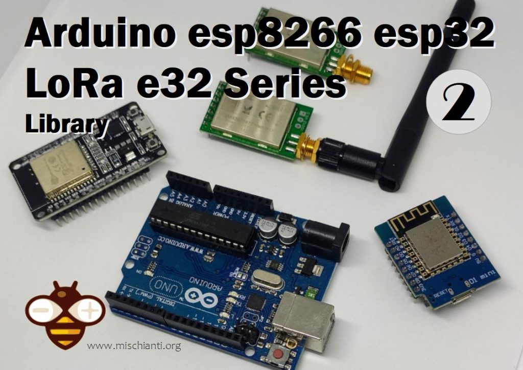
I created a library to manage EBYTE E32 based on the Semtech series of LoRa devices, a potent, simple, and cheap device.

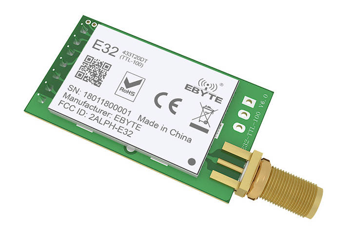
You can find here AliExpress (433MHz 5Km) - AliExpress (433MHz 8Km) - AliExpress (433MHz 16Km) - AliExpress (868MHz 915MHz 5.5Km) - AliExpress (868MHz 915MHz 8Km)
They can work over a distance of 3000m to 8000m, and they have many features and parameters.
So I create this library to simplify the usage.
Library
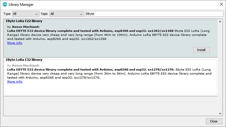
You can find my library here.
And It’s available on Arduino IDE library manager.

To download.
Click the DOWNLOADS button in the top right corner rename the uncompressed folder LoRa_E32.
Check that the LoRa_E32 folder contains LoRa_E32.cpp and LoRa_E32.h.
Place the LoRa_E32 library folder in your /libraries/ folder.
You may need to create the libraries subfolder if it’s your first library.
Restart the IDE.
Pinout
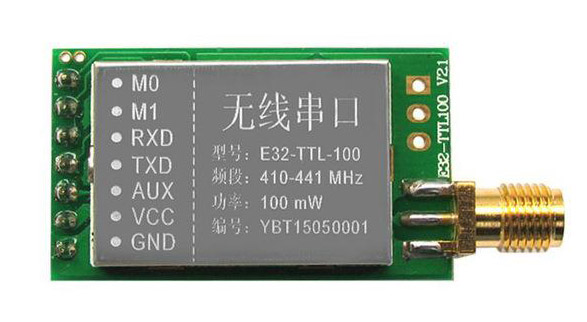
| Pin No. | Pin item | Pin direction | Pin application |
|---|---|---|---|
| 1 | M0 | Input(weak pull-up) | Work with M1 & decide the four operating modes. Floating is not allowed. It can be ground. |
| 2 | M1 | Input(weak pull-up) | Work with M0 & decide the four operating modes. Floating is not allowed. It can be ground. |
| 3 | RXD | Input | TTL UART inputs, connect to external (MCU, PC) TXD output pin. It can be configured as open-drain or pull-up input. |
| 4 | TXD | Output | TTL UART outputs, connect to external RXD (MCU, PC) input pin. Can be configured as open-drain or push-pull output |
5 | AUX | Output | To indicate the module’s working status & wake up the external MCU. During the procedure of self-check initialization, the pin outputs a low level. It can be configured as open-drain or push-pull output (floating is allowed). If you have trouble with the device’s freeze, you must put a pull-up 4.7k resistor or better connect to the device. |
| 6 | VCC | Power supply 2.3V~5.5V DC | |
| 7 | GND | Ground |
As you can see, you can set various modes via M0 and M1 pins.
| Mode | M1 | M0 | Explanation |
|---|---|---|---|
| Normal | 0 | 0 | UART and the wireless channel is good to go |
| Wake-Up | 0 | 1 | Same as standard, but a preamble code is added to transmitted data for waking up the receiver. |
| Power-Saving | 1 | 0 | UART is disabled, and wireless is on WOR(wake on radio) mode, which means the device will turn on when data is received. Transmission is not allowed. |
| Sleep | 1 | 1 | Used in setting parameters. Transmitting and receiving are disabled. |
Some pins can be used statically, but If you connect Them to the microcontroller and configure them in the library, you gain in performance, and you can control all modes via software, but we will explain better next.


Fully connected schema
As I already said, It’s not essential to connect all pins to the output of the microcontroller, you can put M0 and M1 pins to HIGH or LOW to get the desired configuration, and if you don’t connect AUX, the library sets a reasonable delay to be sure that the operation is complete (If you have trouble like freeze device, you must put a pull-up 4.7k resistor or better connect to the device. ).
AUX pin
When transmitting data can be used to wake up external MCU and return HIGH on data transfer finish.

When receiving, AUX goes LOW and returns HIGH when the buffer is empty.

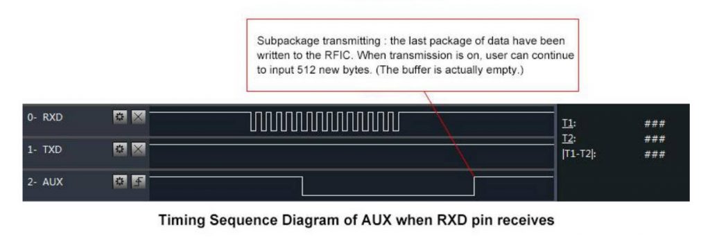
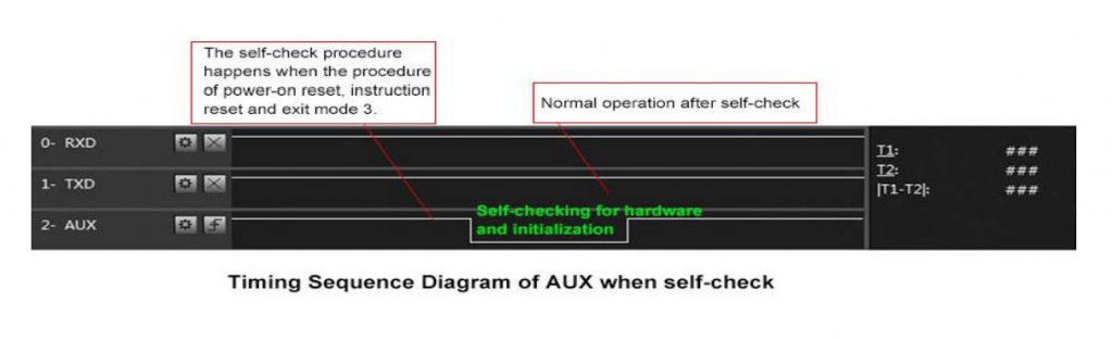
It’s also used for self-checking to restore regular operation (on power-on and sleep/program mode).

esp8266 connection schema is more straightforward because It works at the same voltage of logical communications (3.3v).


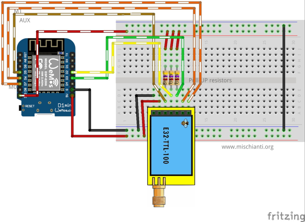
It’s essential to add a pull-up resistor (4,7Kohm) to get good stability.
| M0 | D7 |
| M1 | D6 |
| TX | PIN D2 (PullUP 4,7KΩ) |
| RX | PIN D3 (PullUP 4,7KΩ) |
| AUX | D5 (Input) |
| VCC | 5v (or 3.3v but less power) |
| GND | GND |
Arduino’s working voltage is 5v, so we need to add a voltage divider on RX pin M0 and M1 of the LoRa module to prevent damage. You can get more information here Voltage divider: calculator and application.
You can use a 2Kohm resistor to GND and 1Kohm from the signal, then put it together on RX.
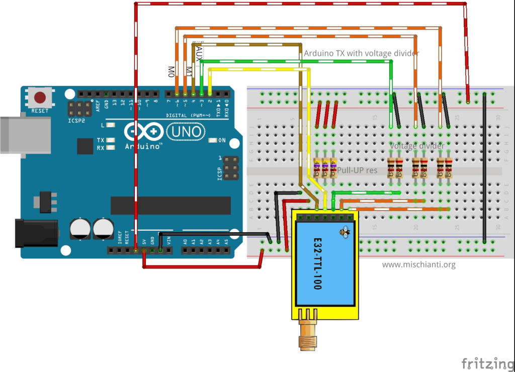
| M0 | 7 (Voltage divider) |
| M1 | 6 (Voltage divider) |
| TX | PIN 2 (PullUP 4,7KΩ) |
| RX | PIN 3 (PullUP 4,7KΩ & Voltage divider) |
| AUX | 5 (Input) |
| VCC | 5v |
| GND | GND |
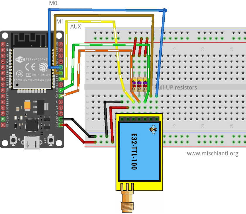
| M0 | D21 |
| M1 | D19 |
| TX | PIN RX2 (PullUP 4,7KΩ) |
| RX | PIN TX3 (PullUP 4,7KΩ) |
| AUX | PIN D18 (PullUP 4,7KΩ) (D15 to wake up) |
| VCC | 5V (but work with less power in 3.3v) |
| GND | GND |
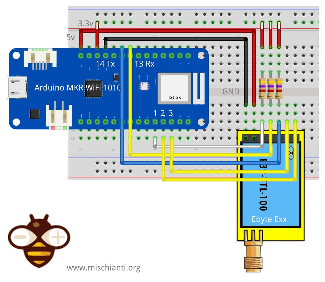
| M0 | 2 (voltage divider) |
| M1 | 3 (voltage divider) |
| TX | PIN 14 Tx (PullUP 4,7KΩ) |
| RX | PIN 13 Rx (PullUP 4,7KΩ) |
| AUX | PIN 1 (PullUP 4,7KΩ) |
| VCC | 5V |
| GND | GND |
Constructor
I made a set of numerous constructors because we can have more options and situations to manage.
		LoRa_E32(byte txE32pin, byte rxE32pin, UART_BPS_RATE bpsRate = UART_BPS_RATE_9600);
		LoRa_E32(byte txE32pin, byte rxE32pin, byte auxPin, UART_BPS_RATE bpsRate = UART_BPS_RATE_9600);
		LoRa_E32(byte txE32pin, byte rxE32pin, byte auxPin, byte m0Pin, byte m1Pin, UART_BPS_RATE bpsRate = UART_BPS_RATE_9600);
The first set of constructors is created to delegate Serial and other pins to the library.
txE32pinandrxE32pinis the pin to connect to UART and they are mandatory.auxPinis a pin that check the operation, transmission and receiving status (we are going to explain better next), that pin It isn’t mandatory, if you don’t set It I apply a delay to permit the operation to complete itself (with latency, if you have trouble, like freeze device, you must put a pull-up 4.7k resistor or better connect to the device ).m0pinandm1Pinare the pins to change operation MODE (see the table upper), I think this pins in “production” are going to connect directly HIGH or LOW, but for test they are usefully to be managed by the library.bpsRateis the boudrate of SoftwareSerial normally is 9600 (the only baud rate in programmin/sleep mode)
A simple example is
#include "LoRa_E32.h"

LoRa_E32 e32ttl100(2, 3);  // e32 TX e32 RX
// LoRa_E32 e32ttl100(2, 3, 5, 6, 7);  // e32 TX e32 RX
We can use a SoftwareSerial directly with another constructor
		LoRa_E32(HardwareSerial* serial, UART_BPS_RATE bpsRate = UART_BPS_RATE_9600);
		LoRa_E32(HardwareSerial* serial, byte auxPin, UART_BPS_RATE bpsRate = UART_BPS_RATE_9600);
		LoRa_E32(HardwareSerial* serial, byte auxPin, byte m0Pin, byte m1Pin, UART_BPS_RATE bpsRate = UART_BPS_RATE_9600);
The example upper with this constructor can be done like so.
#include <SoftwareSerial.h>
#include "LoRa_E32.h"

SoftwareSerial mySerial(2, 3); // e32 TX e32 RX
LoRa_E32 e32ttl100(&mySerial);
// LoRa_E32 e32ttl100(&mySerial, 5, 7, 6);
The last set of constructors permits using an HardwareSerial instead of SoftwareSerial.
		LoRa_E32(SoftwareSerial* serial, UART_BPS_RATE bpsRate = UART_BPS_RATE_9600);
		LoRa_E32(SoftwareSerial* serial, byte auxPin, UART_BPS_RATE bpsRate = UART_BPS_RATE_9600);
		LoRa_E32(SoftwareSerial* serial, byte auxPin, byte m0Pin, byte m1Pin, UART_BPS_RATE bpsRate = UART_BPS_RATE_9600);
For esp32, you have three additional constructors to permit to manage pins for HardWare serial.
			LoRa_E32(byte txE32pin, byte rxE32pin, HardwareSerial* serial, UART_BPS_RATE bpsRate = UART_BPS_RATE_9600, uint32_t serialConfig = SERIAL_8N1);
			LoRa_E32(byte txE32pin, byte rxE32pin, HardwareSerial* serial, byte auxPin, UART_BPS_RATE bpsRate = UART_BPS_RATE_9600, uint32_t serialConfig = SERIAL_8N1);
			LoRa_E32(byte txE32pin, byte rxE32pin, HardwareSerial* serial, byte auxPin, byte m0Pin, byte m1Pin, UART_BPS_RATE bpsRate = UART_BPS_RATE_9600, uint32_t serialConfig = SERIAL_8N1);
Breaking change on esp32 constructor for managed HardwareSerial pins, now reference of HardwareSerial is after the pins to remove ambiguous constructors.
Begin
The begin command is used to startup Serial and pins in input and output mode.
void begin();
in execution is
	// Startup all pins and UART
	e32ttl100.begin();
Configuration and information method
There are many methods for managing configuration and getting information about the device.
		ResponseStructContainer getConfiguration();
		ResponseStatus setConfiguration(Configuration configuration, PROGRAM_COMMAND saveType = WRITE_CFG_PWR_DWN_LOSE);

		ResponseStructContainer getModuleInformation();
        void printParameters(struct Configuration configuration);
        ResponseStatus resetModule();
Response container
To simplify response management, I created a set of containers that usefully manage errors and return generic data.
ResponseStatus
This is a status container with two simple entry points; you can get the status code and the description of the status code.
	Serial.println(c.getResponseDescription()); // Description of code
	Serial.println(c.code); // 1 if Success
The code is
  SUCCESS = 1,
  ERR_UNKNOWN,
  ERR_NOT_SUPPORT,
  ERR_NOT_IMPLEMENT,
  ERR_NOT_INITIAL,
  ERR_INVALID_PARAM,
  ERR_DATA_SIZE_NOT_MATCH,
  ERR_BUF_TOO_SMALL,
  ERR_TIMEOUT,
  ERR_HARDWARE,
  ERR_HEAD_NOT_RECOGNIZED
ResponseContainer
This container is created to manage String response and has two entry points.
data with the string returned from the message and status an instance of RepsonseStatus.
		ResponseContainer rs = e32ttl.receiveMessage();
		String message = rs.data;

		Serial.println(rs.status.getResponseDescription());
		Serial.println(message);
ResponseStructContainer
This is the more “complex” container. I use this to manage structure, It has the same entry point of ResponseContainer, but data is a void pointer to manage complex structure.
	ResponseStructContainer c;
	c = e32ttl100.getConfiguration();
	// It's important get configuration pointer before all other operation
	Configuration configuration = *(Configuration*) c.data;
	Serial.println(c.status.getResponseDescription());
	Serial.println(c.status.code);
        c.close();
Every time you use a ResponseStructContainer you must close It with close()
getConfiguration and setConfiguration
The first method is getConfiguration, and you can use It to retrieve all data stored on the device.
ResponseStructContainer getConfiguration();
Here is a usage example.
	ResponseStructContainer c;
	c = e32ttl100.getConfiguration();
	// It's important get configuration pointer before all other operation
	Configuration configuration = *(Configuration*) c.data;
	Serial.println(c.status.getResponseDescription());
	Serial.println(c.status.code);
        Serial.println(configuration.SPED.getUARTBaudRate());
Structure of configuration have all data of settings, and I add a series of functions to get all description of single data.
	configuration.ADDL = 0x0; // First part of address
	configuration.ADDH = 0x1; // Second part of address
	configuration.CHAN = 0x19;// Channel

	configuration.OPTION.fec = FEC_0_OFF; // Forward error correction switch
	configuration.OPTION.fixedTransmission = FT_TRANSPARENT_TRANSMISSION; // Transmission mode
	configuration.OPTION.ioDriveMode = IO_D_MODE_PUSH_PULLS_PULL_UPS; // Pull-up management
	configuration.OPTION.transmissionPower = POWER_17; // dBm transmission power
	configuration.OPTION.wirelessWakeupTime = WAKE_UP_1250; // Wait time for wake up

	configuration.SPED.airDataRate = AIR_DATA_RATE_011_48; // Air data rate
	configuration.SPED.uartBaudRate = UART_BPS_115200; // Communication baud rate
	configuration.SPED.uartParity = MODE_00_8N1; // Parity bit
You have the equivalent function for all attributes to get all descriptions:
	Serial.print(F("Chan : "));  Serial.print(configuration.CHAN, DEC); Serial.print(" -> "); Serial.println(configuration.getChannelDescription());
	Serial.println(F(" "));
	Serial.print(F("SpeedParityBit     : "));  Serial.print(configuration.SPED.uartParity, BIN);Serial.print(" -> "); Serial.println(configuration.SPED.getUARTParityDescription());
	Serial.print(F("SpeedUARTDatte  : "));  Serial.print(configuration.SPED.uartBaudRate, BIN);Serial.print(" -> "); Serial.println(configuration.SPED.getUARTBaudRate());
	Serial.print(F("SpeedAirDataRate   : "));  Serial.print(configuration.SPED.airDataRate, BIN);Serial.print(" -> "); Serial.println(configuration.SPED.getAirDataRate());

	Serial.print(F("OptionTrans        : "));  Serial.print(configuration.OPTION.fixedTransmission, BIN);Serial.print(" -> "); Serial.println(configuration.OPTION.getFixedTransmissionDescription());
	Serial.print(F("OptionPullup       : "));  Serial.print(configuration.OPTION.ioDriveMode, BIN);Serial.print(" -> "); Serial.println(configuration.OPTION.getIODroveModeDescription());
	Serial.print(F("OptionWakeup       : "));  Serial.print(configuration.OPTION.wirelessWakeupTime, BIN);Serial.print(" -> "); Serial.println(configuration.OPTION.getWirelessWakeUPTimeDescription());
	Serial.print(F("OptionFEC          : "));  Serial.print(configuration.OPTION.fec, BIN);Serial.print(" -> "); Serial.println(configuration.OPTION.getFECDescription());
	Serial.print(F("OptionPower        : "));  Serial.print(configuration.OPTION.transmissionPower, BIN);Serial.print(" -> "); Serial.println(configuration.OPTION.getTransmissionPowerDescription());
In the same way, setConfiguration wants a configuration structure, so I think the better way to manage configuration is to retrieve the current one, apply the only change you need and set It again.
ResponseStatus setConfiguration(Configuration configuration, PROGRAM_COMMAND saveType = WRITE_CFG_PWR_DWN_LOSE);
configuration is the structure previously shown, saveType permit you to choose if the difference becomes permanent or only for the current session.
	ResponseStructContainer c;
	c = e32ttl100.getConfiguration();
	// It's important get configuration pointer before all other operation
	Configuration configuration = *(Configuration*) c.data;
	Serial.println(c.status.getResponseDescription());
	Serial.println(c.status.code);

	printParameters(configuration);
	configuration.ADDL = 0x0;
	configuration.ADDH = 0x1;
	configuration.CHAN = 0x19;

	configuration.OPTION.fec = FEC_0_OFF;
	configuration.OPTION.fixedTransmission = FT_TRANSPARENT_TRANSMISSION;
	configuration.OPTION.ioDriveMode = IO_D_MODE_PUSH_PULLS_PULL_UPS;
	configuration.OPTION.transmissionPower = POWER_17;
	configuration.OPTION.wirelessWakeupTime = WAKE_UP_1250;

	configuration.SPED.airDataRate = AIR_DATA_RATE_011_48;
	configuration.SPED.uartBaudRate = UART_BPS_115200;
	configuration.SPED.uartParity = MODE_00_8N1;

	// Set configuration changed and set to not hold the configuration
	ResponseStatus rs = e32ttl100.setConfiguration(configuration, WRITE_CFG_PWR_DWN_LOSE);
	Serial.println(rs.getResponseDescription());
	Serial.println(rs.code);
	printParameters(configuration);
The parameters are all managed as constant:
Basic configuration option
| ADDH | High address byte of the module (the default 00H) | 00H-FFH |
| ADDL | Low address byte of the module (the default 00H) | 00H-FFH |
| SPED | Information about data rate parity bit and Air data rate | |
| CHAN | Communication channel(410M + CHAN*1M), default 17H (433MHz), valid only for 433MHz device check below to check the correct frequency of your device | 00H-1FH |
| OPTION | Type of transmission, pull-up settings, wake-up time, FEC, Transmission power |
SPED detail
UART Parity bit: UART mode can be different between communication parties
| 7 | 6 | UART parity bit | Constant value |
|---|---|---|---|
| 0 | 0 | 8N1 (default) | MODE_00_8N1 |
| 0 | 1 | 8O1 | MODE_01_8O1 |
| 1 | 0 | 8 E1 | MODE_10_8E1 |
| 1 | 1 | 8N1 (equal to 00) | MODE_11_8N1 |
UART baud rate: UART baud rate can be different between communication parties. The UART baud rate has nothing to do with wireless transmission parameters & won’t affect the wireless transmit/receive features.
| 5 | 4 | 3 | TTL UART baud rate(bps) | Constant value |
|---|---|---|---|---|
| 0 | 0 | 0 | 1200 | UART_BPS_1200 |
| 0 | 0 | 1 | 2400 | UART_BPS_2400 |
| 0 | 1 | 0 | 4800 | UART_BPS_4800 |
| 0 | 1 | 1 | 9600 (default) | UART_BPS_9600 |
| 1 | 0 | 0 | 19200 | UART_BPS_19200 |
| 1 | 0 | 1 | 38400 | UART_BPS_38400 |
| 1 | 1 | 0 | 57600 | UART_BPS_57600 |
| 1 | 1 | 1 | 115200 | UART_BPS_115200 |
Air data rate: The lower the air data rate, the longer the transmitting distance, better anti-interference performance, and longer transmitting time; the air data rate must be constant for both communication parties.
| 2 | 1 | 0 | Air data rate(bps) | Constant value |
|---|---|---|---|---|
| 0 | 0 | 0 | 0.3k | AIR_DATA_RATE_000_03 |
| 0 | 0 | 1 | 1.2k | AIR_DATA_RATE_001_12 |
| 0 | 1 | 0 | 2.4k (default) | AIR_DATA_RATE_010_24 |
| 0 | 1 | 1 | 4.8k | AIR_DATA_RATE_011_48 |
| 1 | 0 | 0 | 9.6k | AIR_DATA_RATE_100_96 |
| 1 | 0 | 1 | 19.2k | AIR_DATA_RATE_101_192 |
| 1 | 1 | 0 | 19.2k (same to 101) | AIR_DATA_RATE_110_192 |
| 1 | 1 | 1 | 19.2k (same to 101) | AIR_DATA_RATE_111_192 |
OPTION detail
Transmission mode: The first three bytes of each user’s data frame can be used as high/low address and channel in fixed transmission mode. The module changes its address and channel when transmitted. And it will revert to the original setting after completing the process.
| 7 | Fixed transmission enabling bit(similar to MODBUS) | Constant value |
|---|---|---|
| 0 | Transparent transmission mode | FT_TRANSPARENT_TRANSMISSION |
| 1 | Fixed transmission mode | FT_FIXED_TRANSMISSION |
IO drive mode: this bit is used for the module internal pull-up resistor. It also increases the level’s adaptability in case of an open drain. But in some cases, it may need an external pull-up resistor.
| 6 | IO drive mode ( default 1) | Constant value |
|---|---|---|
| 1 | TXD and AUX push-pull outputs, RXD pull-up inputs | IO_D_MODE_PUSH_PULLS_PULL_UPS |
| 0 | TXD、AUX open-collector outputs, RXD open-collector inputs | IO_D_MODE_OPEN_COLLECTOR |
Wireless wake-up time: the transmit & receive module work in mode 0, whose delay time is invalid & can be an arbitrary value; the transmitter works in mode one can send the preamble code of the corresponding time continuously when the receiver operates in mode 2, the time means the monitor interval time (wireless wake-up). Only the data from the transmitter that works in mode one can be
received.
| 5 | 4 | 3 | Wireless wake-up time | Constant value |
|---|---|---|---|---|
| 0 | 0 | 0 | 250ms (default) | WAKE_UP_250 |
| 0 | 0 | 1 | 500ms | WAKE_UP_500 |
| 0 | 1 | 0 | 750ms | WAKE_UP_750 |
| 0 | 1 | 1 | 1000ms | WAKE_UP_1000 |
| 1 | 0 | 0 | 1250ms | WAKE_UP_1250 |
| 1 | 0 | 1 | 1500ms | WAKE_UP_1500 |
| 1 | 1 | 0 | 1750ms | WAKE_UP_1750 |
| 1 | 1 | 1 | 2000ms | WAKE_UP_2000 |
FEC: after turning off FEC, the actual data transmission rate increases while anti-interference ability decreases. Also, the transmission distance is relatively short, and both communication parties must keep on the same pages about turn-on or turn-off FEC.
| 2 | FEC switch | Constant value |
|---|---|---|
| 0 | Turn off FEC | FEC_0_OFF |
| 1 | Turn on FEC (default) | FEC_1_ON |
Transmission power
You can change this set of constants by applying a definition like so:
#define E32_TTL_100 // default value without set
Applicable for E32-TTL-100, E32-TTL-100S1, E32-T100S2.
The external power must make sure the current output ability is more than 250mA and ensure the power supply ripple within 100mV.
Low power transmission is not recommended due to its low power supply
efficiency.
#define E32_TTL_100 // default value without set
| 1 | 0 | Transmission power (approximation) | Constant value |
|---|---|---|---|
| 0 | 0 | 20dBm (default) | POWER_20 |
| 0 | 1 | 17dBm | POWER_17 |
| 1 | 0 | 14dBm | POWER_14 |
| 1 | 1 | 10dBm | POWER_10 |
Applicable for E32-TTL-500。
The external power must make sure the current output ability is more than 700mA and ensure the power supply ripple within 100mV.
Low power transmission is not recommended due to its low power supply efficiency.
#define E32_TTL_500
| 1 | 0 | Transmission power (approximation) | Constant value |
|---|---|---|---|
| 0 | 0 | 27dBm (default) | POWER_27 |
| 0 | 1 | 24dBm | POWER_24 |
| 1 | 0 | 21dBm | POWER_21 |
| 1 | 1 | 18dBm | POWER_18 |
Applicable for E32-TTL-1W, E32 (433T30S), E32 (868T30S), E32 (915T30S)
The external power must make sure the current output ability is more than 1A and ensure the power supply ripple within 100mV.
Low power transmission is not recommended due to its low power supply
efficiency.
#define E32_TTL_1W
| 1 | 0 | Transmission power (approximation) | Constant value |
|---|---|---|---|
| 0 | 0 | 30dBm (default) | POWER_30 |
| 0 | 1 | 27dBm | POWER_27 |
| 1 | 0 | 24dBm | POWER_24 |
| 1 | 1 | 21dBm | POWER_21 |
You can configure Channel frequency also with this define:
// One of
#define FREQUENCY_433
#define FREQUENCY_170
#define FREQUENCY_470
#define FREQUENCY_868
#define FREQUENCY_915
Send receive message
First, we must introduce a simple but usefully method to check if something is in the receiving buffer
int available();
It’s simple to return how many bytes you have in the current stream.
Normal transmission mode
Normal/Transparent transmission mode sends messages to all devices with the same address and channel.

There is a lot of methods to send/receive messages, and we are going to explain in detail:
        ResponseStatus sendMessage(const String message);
        ResponseContainer receiveMessage();
The first method is sendMessage and is used to send a String to a device in Normal mode.
	ResponseStatus rs = e32ttl.sendMessage("Prova");
	Serial.println(rs.getResponseDescription());
The other device simply does on the loop.
       if (e32ttl.available()  > 1){
		ResponseContainer rs = e32ttl.receiveMessage();
		String message = rs.data; // First ever get the data
		Serial.println(rs.status.getResponseDescription());
		Serial.println(message);
	}
Pay attention if you receive multiple messages in the buffer, and you don’t want reading all in one time you must use ResponseContainer rs = e32ttl.receiveMessageUntil();
Manage structure
If you wish to send a complex structure, you can use this method
        ResponseStatus sendMessage(const void *message, const uint8_t size);
        ResponseStructContainer receiveMessage(const uint8_t size);
It’s used to send structure, for example:
	struct Messaggione {
		char type[5];
		char message[8];
		bool mitico;
	};
        struct Messaggione messaggione = {"TEMP", "Peple", true};
        ResponseStatus rs = e32ttl.sendMessage(&messaggione, sizeof(Messaggione));
	Serial.println(rs.getResponseDescription());
and the other side, you can receive the message so
		ResponseStructContainer rsc = e32ttl.receiveMessage(sizeof(Messaggione));
		struct Messaggione messaggione = *(Messaggione*) rsc.data;
		Serial.println(messaggione.message);
		Serial.println(messaggione.mitico);
Read partial structure
If you want to read the first part of the message to manage more types of structure, you can use this method.
ResponseContainer receiveInitialMessage(const uint8_t size);
I create It to receive a string with type or other to identify the structure to load.
		struct Messaggione { // Partial strucutre without type
			char message[8];
			bool mitico;
		};

		char type[5]; // first part of structure
		ResponseContainer rs = e32ttl.receiveInitialMessage(sizeof(type));
                // Put string in a char array (not needed)
		memcpy ( type, rs.data.c_str(), sizeof(type) );

		Serial.println("READ TYPE: ");
		Serial.println(rs.status.getResponseDescription());
		Serial.println(type);

                // Read the rest of structure
		ResponseStructContainer rsc = e32ttl.receiveMessage(sizeof(Messaggione));
		struct Messaggione messaggione = *(Messaggione*) rsc.data;
Fixed mode instead of normal mode
In some manner, I create a set of methods to use with fixed transmission
Fixed transmission
You need to change only the sending method because the destination device doesn’t receive the preamble with Address and Channel when setting the fixed mode.
So for the String message, you have
        ResponseStatus sendFixedMessage(byte ADDH, byte ADDL, byte CHAN, const String message);
        ResponseStatus sendBroadcastFixedMessage(byte CHAN, const String message);
and for the structure, you have
        ResponseStatus sendFixedMessage(byte ADDH, byte ADDL, byte CHAN, const void *message, const uint8_t size);
        ResponseStatus sendBroadcastFixedMessage(byte CHAN, const void *message, const uint8_t size );
Here is a simple example
	ResponseStatus rs = e32ttl.sendFixedMessage(0, 0, 0x17, &messaggione, sizeof(Messaggione));
//	ResponseStatus rs = e32ttl.sendFixedMessage(0, 0, 0x17, "Ciao");
Fixed transmission have more scenarios
If you send to a specific device (second scenario Fixed transmission), you must add ADDL, ADDH, and CHAN to identify It directly.
ResponseStatus rs = e32ttl.sendFixedMessage(2, 2, 0x17, "Message to a device");
If you want to send a message to all devices in a specified Channel, you can use this method.
ResponseStatus rs = e32ttl.sendBroadcastFixedMessage(0x17, "Message to a devices of a channel");
If you wish to receive all broadcast messages in the network, you must set your ADDH and ADDL with BROADCAST_ADDRESS.
        ResponseStructContainer c;
	c = e32ttl100.getConfiguration();
	// It's important get configuration pointer before all other operation
	Configuration configuration = *(Configuration*) c.data;
	Serial.println(c.status.getResponseDescription());
	Serial.println(c.status.code);

	printParameters(configuration);
	configuration.ADDL = BROADCAST_ADDRESS;
	configuration.ADDH = BROADCAST_ADDRESS;

	// Set configuration changed and set to not hold the configuration
	ResponseStatus rs = e32ttl100.setConfiguration(configuration, WRITE_CFG_PWR_DWN_LOSE);
	Serial.println(rs.getResponseDescription());
	Serial.println(rs.code);
	printParameters(configuration);
Thanks
Now you have all information to do your work, but I think It’s important to show some real examples to understand better all the possibilities.
- LoRa E32 device for Arduino, esp32 or esp8266: settings and basic usage
- LoRa E32 device for Arduino, esp32 or esp8266: library
- LoRa E32 device for Arduino, esp32 or esp8266: configuration
- LoRa E32 device for Arduino, esp32 or esp8266: fixed transmission
- LoRa E32 device for Arduino, esp32 or esp8266: power saving and sending structured data
- LoRa E32 device for Arduino, esp32 or esp8266: WOR (wake on radio) microcontroller and Arduino shield
- LoRa E32 device for Arduino, esp32 or esp8266: WOR (wake on radio) microcontroller and WeMos D1 shield
- EByte LoRa E32 device for Arduino, esp32 or esp8266: WOR (wake on radio) and new ESP32 shield
- Ebyte LoRa E32 with STM32: WOR (wake on radio) and new STM32 shield
- Mischianti Arduino LoRa shield (Open source)
- Mischianti WeMos LoRa shield (Open source)
- Mischianti ESP32 DOIT DEV KIT v1 shield (Open source)
- STM32F1 Blue-Pill EByte LoRa E32, E22, and E220 Shield
- STM32F4 Black-Pill EByte LoRa E32, E22, and E220 Shield