
Unleashing IoT Potential: Integrating STM32F1 Blue-Pill with EByte LoRa E32, E22, and E220 Shields
The Internet of Things (IoT) landscape is evolving at a rapid pace, leading to an increased demand for robust and scalable communication technologies. LoRa, or Long Range, is one such technology that has gained significant traction in recent years. In this article, we will delve into the integration of STM32F1 Blue-Pill, a highly capable microcontroller, with EByte LoRa E32, E22, and E220 shield modules, which are popular for long-range, low-power applications.
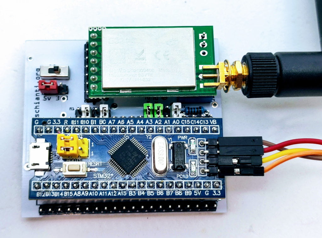
I start using STM32 microcontrollers, and I find they are of superior quality. But I need a prototyping board to do my work faster.
EByte LoRa E32, E22, and E220 Shield Modules
EByte LoRa E32, E22, and E220 are powerful, high-quality LoRa transceiver modules that provide long-range, low-power wireless solutions. These modules support LoRa modulation for LPWAN (Low Power Wide Area Network) and comply with the LoRaWAN Class A protocol, making them ideal for IoT applications.
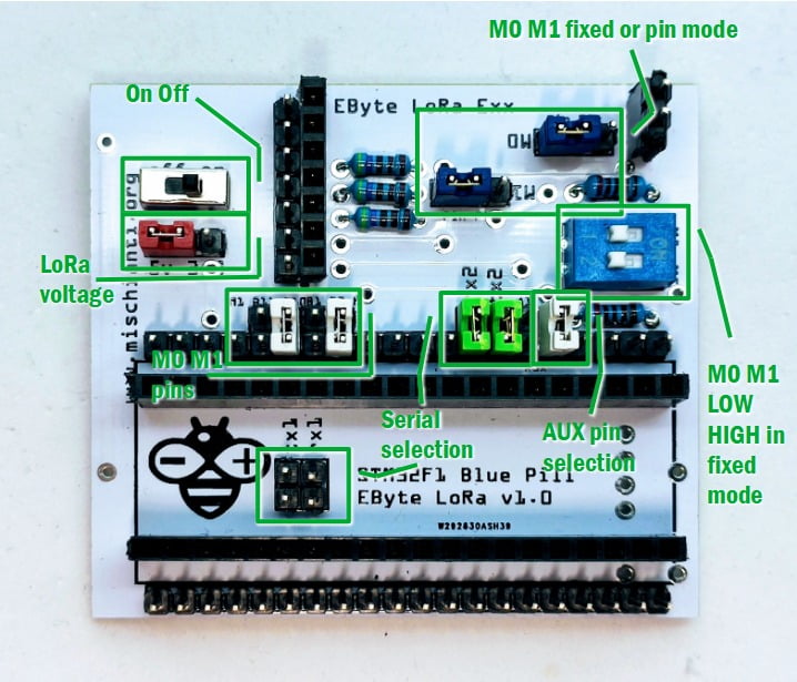
STM32F1 pinout
As you can see in the pinout diagram, you can find more than one Serial interface. In this board, I add jumpers to select Serial1 (Tx -> PA9, Rx->PA10) and Serial2 (Tx -> PA2, and Rx->PA3) interface.
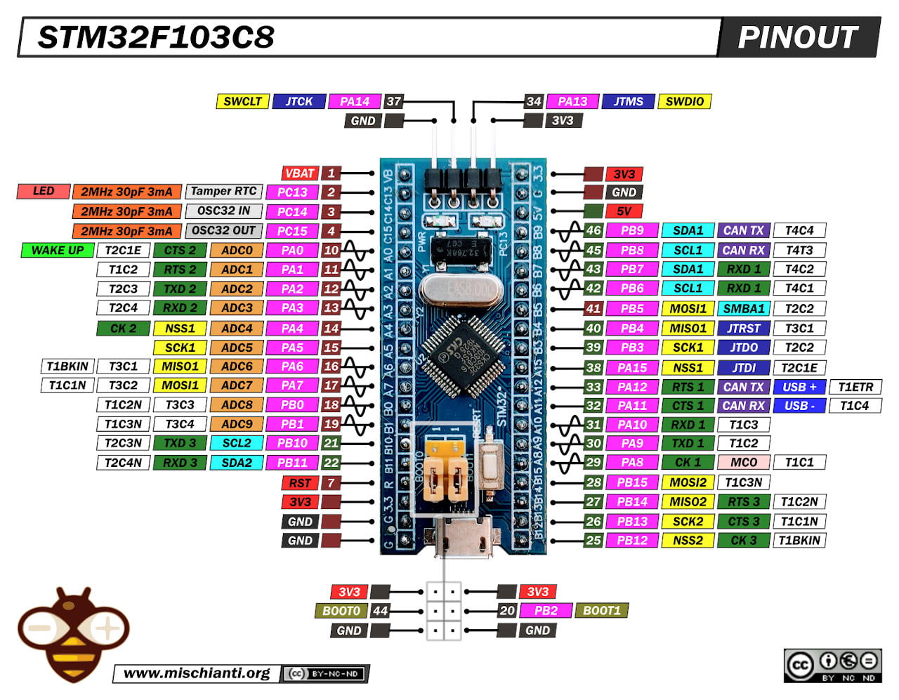
The selectable pins are also AUX, M0, and M1.
Here my selection of STM32 STM32F103C8T6 STM32F401 STM32F411 ST-Link v2 ST-Link v2 official
For AUX I put PA0 (or WAKE pin) and PA1, for M0 you can select B0 and B1, for M1 the B2 and B10.
You can also put M0 and M1 in fixed mode and select the static status in the DIP-switch.
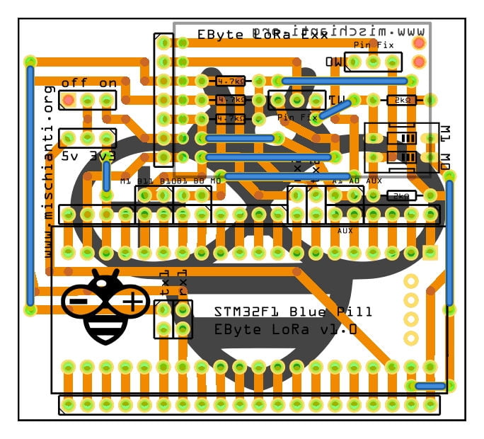
PCB
You can order the PCB from PCBWay for few dollars PCBWay

As usual, I create a PCB that can be milled, so when I send It to the factory for production, I’m sure that it works correctly.
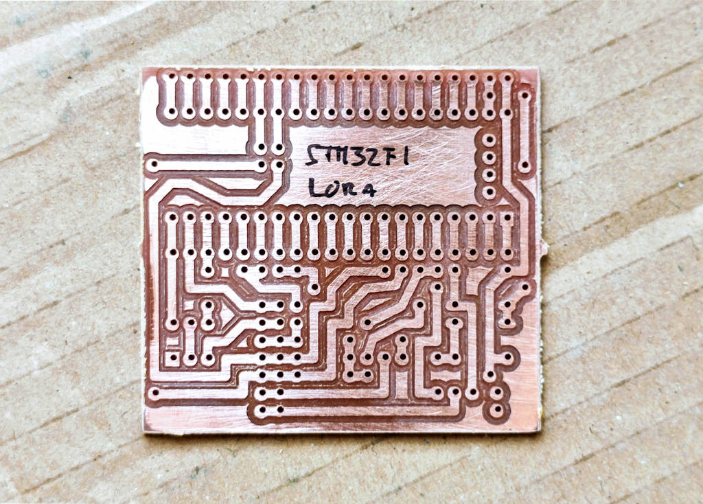
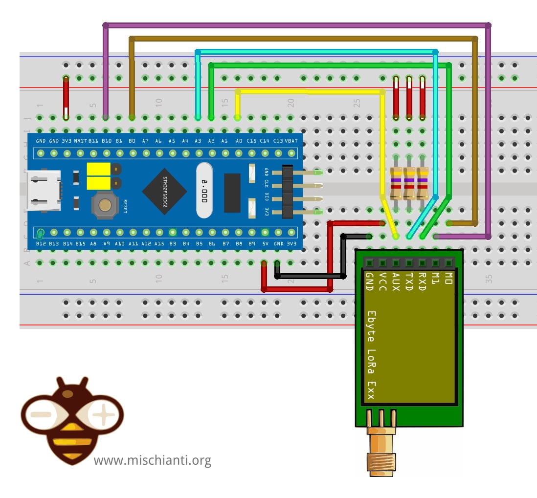
The design is quite simple, you can check the connection in the PCB schema:
The standard configuration is:
HardwareSerial Serial2(USART2);   // PA3  (RX)  PA2  (TX)
LoRa_E32 e32ttl(&Serial2, PA0, PB0, PB10); //  Serial2 AUX M0 M1
But, as already described, you can select with the jumpers other configuration:
- Serial1 (
Tx->PA9, Rx->PA10) or Serial2 (Tx->PA2, Rx->PA3); AUXwithPA0(or WAKE pin) andPA1;M0you can selectB0andB1;M1you can selectB2andB10.
Here is the PCB description to better understand.
Shopping List
EByte LoRa E32 AliExpress (433MHz 5Km) - AliExpress (433MHz 8Km) - AliExpress (433MHz 16Km) - AliExpress (868MHz 915MHz 5.5Km) - AliExpress (868MHz 915MHz 8Km)
EByte LoRa E22 AliExpress (433MHz 5.5Km) - AliExpress (433MHz 10Km) - AliExpress (868MHz 915Mhz 5.5Km) - AliExpress (868MHz 915Mhz 10Km)
EByte LoRa E220 E220-400T22D 433MHz 5Km - E220-400T30D 433MHz 10Km - E220-900T22D 868MHz 915MHz 5Km - E220-900T30D 868MHz 915MHz 10Km
Amount Part Type Properties 1 Lora Exx variant 1; voltage 3-5V; type Basic 1 DIP SWITCH channels 1; package dipswitch-02 2 Generic male header – 3 pins pins 3; pin spacing 0.1in (2.54mm); hole size 1.0mm,0.508mm; form ♂ (male); package THT; row single 3 4.7kΩ Resistor bands 4; tolerance ±5%; pin spacing 400 mil; package THT; resistance 4.7kΩ 3 2kΩ Resistor bands 4; tolerance ±5%; pin spacing 400 mil; package THT; resistance 2kΩ Generic female header Pin spacing 0.1in (2.54mm); Generic male/female header Pin spacing 0.1in (2.54mm);
Configuration and test
I’m going to explain a simple sketch to get the configuration of an EByte LoRa E220. First of all, remember to set the correct constructor with the correct selection of the pin.
/*
 * LoRa E220
 * Get configuration.
 * You must uncommend the correct constructor.
 *
 * by Renzo Mischianti <https://mischianti.org>
 *
 * https://mischianti.org
 *
 * E220		  ----- WeMos D1 mini	----- esp32			----- Arduino Nano 33 IoT	----- Arduino MKR	----- Raspberry Pi Pico   ----- stm32               ----- ArduinoUNO
 * M0         ----- D7 (or 3.3v)	----- 19 (or 3.3v)	----- 4 (or 3.3v)			----- 2 (or 3.3v)	----- 10 (or 3.3v)	      ----- PB0 (or 3.3v)       ----- 7 Volt div (or 3.3v)
 * M1         ----- D6 (or 3.3v)	----- 21 (or 3.3v)	----- 6 (or 3.3v)			----- 4 (or 3.3v)	----- 11 (or 3.3v)	      ----- PB10 (or 3.3v)      ----- 6 Volt div (or 3.3v)
 * TX         ----- D3 (PullUP)		----- TX2 (PullUP)	----- TX1 (PullUP)			----- 14 (PullUP)	----- 8 (PullUP)	      ----- PA2 TX2 (PullUP)    ----- 4 (PullUP)
 * RX         ----- D4 (PullUP)		----- RX2 (PullUP)	----- RX1 (PullUP)			----- 13 (PullUP)	----- 9 (PullUP)	      ----- PA3 RX2 (PullUP)    ----- 5 Volt div (PullUP)
 * AUX        ----- D5 (PullUP)		----- 18  (PullUP)	----- 2  (PullUP)			----- 0  (PullUP)	----- 2  (PullUP)	      ----- PA0  (PullUP)       ----- 3 (PullUP)
 * VCC        ----- 3.3v/5v			----- 3.3v/5v		----- 3.3v/5v				----- 3.3v/5v		----- 3.3v/5v		      ----- 3.3v/5v             ----- 3.3v/5v
 * GND        ----- GND				----- GND			----- GND					----- GND			----- GND			      ----- GND                 ----- GND
 *
 */

#include "Arduino.h"
#include "LoRa_E220.h"

// ---------- esp8266 pins --------------
//LoRa_E220 e220ttl(RX, TX, AUX, M0, M1);  // Arduino RX <-- e220 TX, Arduino TX --> e220 RX
//LoRa_E220 e220ttl(D3, D4, D5, D7, D6); // Arduino RX <-- e220 TX, Arduino TX --> e220 RX AUX M0 M1
//LoRa_E220 e220ttl(D2, D3); // Config without connect AUX and M0 M1

//#include <SoftwareSerial.h>
//SoftwareSerial mySerial(D2, D3); // Arduino RX <-- e220 TX, Arduino TX --> e220 RX
//LoRa_E220 e220ttl(&mySerial, D5, D7, D6); // AUX M0 M1
// -------------------------------------

// ---------- Arduino pins --------------
//LoRa_E220 e220ttl(4, 5, 3, 7, 6); // Arduino RX <-- e220 TX, Arduino TX --> e220 RX AUX M0 M1
//LoRa_E220 e220ttl(4, 5); // Config without connect AUX and M0 M1

//#include <SoftwareSerial.h>
//SoftwareSerial mySerial(4, 5); // Arduino RX <-- e220 TX, Arduino TX --> e220 RX
//LoRa_E220 e220ttl(&mySerial, 3, 7, 6); // AUX M0 M1
// -------------------------------------

// ------------- Arduino Nano 33 IoT -------------
// LoRa_E220 e220ttl(&Serial1, 2, 4, 6); //  RX AUX M0 M1
// -------------------------------------------------

// ------------- Arduino MKR WiFi 1010 -------------
// LoRa_E220 e220ttl(&Serial1, 0, 2, 4); //  RX AUX M0 M1
// -------------------------------------------------

// ---------- esp32 pins --------------
// LoRa_E220 e220ttl(&Serial2, 15, 21, 19); //  RX AUX M0 M1

//LoRa_E220 e220ttl(&Serial2, 22, 4, 18, 21, 19, UART_BPS_RATE_9600); //  esp32 RX <-- e220 TX, esp32 TX --> e220 RX AUX M0 M1
// -------------------------------------

// ---------- Raspberry PI Pico pins --------------
// LoRa_E220 e220ttl(&Serial2, 2, 10, 11); //  RX AUX M0 M1
// -------------------------------------

// ---------------- STM32 --------------------
HardwareSerial Serial2(USART2);   // PA3  (RX)  PA2  (TX)
LoRa_E220 e220ttl(&Serial2, PA0, PB0, PB10); //  RX AUX M0 M1
// -------------------------------------------------

void printParameters(struct Configuration configuration);
void printModuleInformation(struct ModuleInformation moduleInformation);

void setup() {
	Serial.begin(9600);
	while(!Serial){};
	delay(500);

	Serial.println();


	// Startup all pins and UART
	e220ttl.begin();

	ResponseStructContainer c;
	c = e220ttl.getConfiguration();
	// It's important get configuration pointer before all other operation
	Configuration configuration = *(Configuration*) c.data;
	Serial.println(c.status.getResponseDescription());
	Serial.println(c.status.code);

	printParameters(configuration);

	ResponseStructContainer cMi;
	cMi = e220ttl.getModuleInformation();
	// It's important get information pointer before all other operation
	ModuleInformation mi = *(ModuleInformation*)cMi.data;

	Serial.println(cMi.status.getResponseDescription());
	Serial.println(cMi.status.code);

	printModuleInformation(mi);
}

void loop() {

}
void printParameters(struct Configuration configuration) {
	Serial.println("----------------------------------------");

	Serial.print(F("HEAD : "));  Serial.print(configuration.COMMAND, HEX);Serial.print(" ");Serial.print(configuration.STARTING_ADDRESS, HEX);Serial.print(" ");Serial.println(configuration.LENGHT, HEX);
	Serial.println(F(" "));
	Serial.print(F("AddH : "));  Serial.println(configuration.ADDH, HEX);
	Serial.print(F("AddL : "));  Serial.println(configuration.ADDL, HEX);
	Serial.println(F(" "));
	Serial.print(F("Chan : "));  Serial.print(configuration.CHAN, DEC); Serial.print(" -> "); Serial.println(configuration.getChannelDescription());
	Serial.println(F(" "));
	Serial.print(F("SpeedParityBit     : "));  Serial.print(configuration.SPED.uartParity, BIN);Serial.print(" -> "); Serial.println(configuration.SPED.getUARTParityDescription());
	Serial.print(F("SpeedUARTDatte     : "));  Serial.print(configuration.SPED.uartBaudRate, BIN);Serial.print(" -> "); Serial.println(configuration.SPED.getUARTBaudRateDescription());
	Serial.print(F("SpeedAirDataRate   : "));  Serial.print(configuration.SPED.airDataRate, BIN);Serial.print(" -> "); Serial.println(configuration.SPED.getAirDataRateDescription());
	Serial.println(F(" "));
	Serial.print(F("OptionSubPacketSett: "));  Serial.print(configuration.OPTION.subPacketSetting, BIN);Serial.print(" -> "); Serial.println(configuration.OPTION.getSubPacketSetting());
	Serial.print(F("OptionTranPower    : "));  Serial.print(configuration.OPTION.transmissionPower, BIN);Serial.print(" -> "); Serial.println(configuration.OPTION.getTransmissionPowerDescription());
	Serial.print(F("OptionRSSIAmbientNo: "));  Serial.print(configuration.OPTION.RSSIAmbientNoise, BIN);Serial.print(" -> "); Serial.println(configuration.OPTION.getRSSIAmbientNoiseEnable());
	Serial.println(F(" "));
	Serial.print(F("TransModeWORPeriod : "));  Serial.print(configuration.TRANSMISSION_MODE.WORPeriod, BIN);Serial.print(" -> "); Serial.println(configuration.TRANSMISSION_MODE.getWORPeriodByParamsDescription());
	Serial.print(F("TransModeEnableLBT : "));  Serial.print(configuration.TRANSMISSION_MODE.enableLBT, BIN);Serial.print(" -> "); Serial.println(configuration.TRANSMISSION_MODE.getLBTEnableByteDescription());
	Serial.print(F("TransModeEnableRSSI: "));  Serial.print(configuration.TRANSMISSION_MODE.enableRSSI, BIN);Serial.print(" -> "); Serial.println(configuration.TRANSMISSION_MODE.getRSSIEnableByteDescription());
	Serial.print(F("TransModeFixedTrans: "));  Serial.print(configuration.TRANSMISSION_MODE.fixedTransmission, BIN);Serial.print(" -> "); Serial.println(configuration.TRANSMISSION_MODE.getFixedTransmissionDescription());


	Serial.println("----------------------------------------");
}
void printModuleInformation(struct ModuleInformation moduleInformation) {
	Serial.println("----------------------------------------");
	Serial.print(F("HEAD: "));  Serial.print(moduleInformation.COMMAND, HEX);Serial.print(" ");Serial.print(moduleInformation.STARTING_ADDRESS, HEX);Serial.print(" ");Serial.println(moduleInformation.LENGHT, DEC);

	Serial.print(F("Model no.: "));  Serial.println(moduleInformation.model, HEX);
	Serial.print(F("Version  : "));  Serial.println(moduleInformation.version, HEX);
	Serial.print(F("Features : "));  Serial.println(moduleInformation.features, HEX);
	Serial.println("----------------------------------------");
}
And here is the Serial output.
Success
1
----------------------------------------
HEAD : C1 0 8

AddH : 0
AddL : 3

Chan : 23 -> 433MHz

SpeedParityBit     : 0 -> 8N1 (Default)
SpeedUARTDatte     : 11 -> 9600bps (default)
SpeedAirDataRate   : 10 -> 2.4kbps (default)

OptionSubPacketSett: 0 -> 200bytes (default)
OptionTranPower    : 0 -> 22dBm (Default)
OptionRSSIAmbientNo: 0 -> Disabled (default)

TransModeWORPeriod : 11 -> 2000ms (default)
TransModeEnableLBT : 0 -> Disabled (default)
TransModeEnableRSSI: 0 -> Disabled (default)
TransModeFixedTrans: 1 -> Fixed transmission (first three bytes can be used as high/low address and channel)
----------------------------------------
Success
1
----------------------------------------
HEAD: C1 8 3
Model no.: 13
Version  : A
Features : 16
----------------------------------------
Thanks
- STM32F1 Blue-Pill: pinout, specs, and Arduino IDE configuration (STM32duino and STMicroelectronics)
- STM32: program (STM32F1) via USB with STM32duino bootloader
- STM32: programming (STM32F1 STM32F4) via USB with HID boot-loader
- STM32F4 Black-Pill: pinout, specs, and Arduino IDE configuration
- STM32: ethernet w5500 with plain HTTP and SSL (HTTPS)
- STM32: ethernet enc28j60 with plain HTTP and SSL (HTTPS)
- STM32: WiFiNINA with ESP32 WiFi Co-Processor
- How to use SD card with stm32 and SdFat library
- \STM32: SPI flash memory FAT FS
- STM32: internal RTC, clock, and battery backup (VBAT)
- STM32 LoRa
- STM32 Power saving
- STM32F1 Blue-Pill clock and frequency management
- STM32F4 Black-Pill clock and frequency management
- Intro and Arduino vs STM framework
- Library LowPower, wiring, and Idle (STM Sleep) mode
- Sleep, deep sleep, shutdown, and power consumption
- Wake up from RTC alarm and Serial
- Wake up from the external source
- Backup domain intro and variable preservation across reset
- RTC backup register and SRAM preservation
- STM32 send emails with attachments and SSL (like Gmail): w5500, enc28j60, SD, and SPI Fash
- FTP server on STM32 with w5500, enc28j60, SD Card, and SPI Flash


Hello,
I am looking for help developing and integrating the Ebyte LoRa E20 module with the DS18b20 temp sensor.
also, the possibility to transmit the data to an E20 receiver which be connected to Ebyte M1 Uart to LAN
Hi Haim,
I don’t know that kind of devices, but if you open a forum topic with the problems you encounter in your develop we try to help you.
Bye Renzo