
STM32: internal RTC, clock and battery backup (VBAT)
Welcome to our comprehensive article on the STM32’s internal Real-Time Clock (RTC), clock system, and battery backup (VBAT). In today’s fast-paced world, precise timekeeping and effective power management are essential elements of modern embedded systems. The STM32 family of microcontrollers, with their feature-rich capabilities, offers an excellent solution to address these requirements.
A real-time clock (RTC) is a computer clock that keeps track of the current time. The microcontrollers supporting the RTC can be used for chronometers, alarm clocks, watches, small electronic agendas, and many other devices.
In the STM32, the real-time clock (RTC) is an independent BCD timer/counter. Dedicated registers contain the second, minute, hour (in 12/24 hour), weekday, date, month, year in BCD (binary-coded decimal) format. Correction for 28, 29 (leap year), 30, and 31 days of the month are performed automatically. The RTC features a reference clock detection, a more precise second source clock (50 or 60 Hz) can be used to enhance the calendar precision. The RTC provides a programmable alarm and programmable periodic interrupts with wakeup from Stop and Standby modes
VBAT operation is activated when VDD is not present. A symbiotic element is the VBAT pin, which allows the power of the device VBAT domain from an external battery, an external super-capacitor, or from VDD when no external battery and an external super-capacitor are present. The VBAT pin supplies the RTC and the backup registers.
Detail
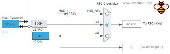
This RTC can be used with three clock sources:
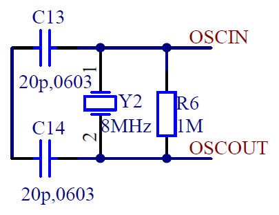
- HSE is a high-speed external clock, which can be connected with a quartz/ceramic resonator or external clock source. Its frequency range is from 4MHz to 16MHz.
The high-speed external oscillator provides a safe crystal system clock. A clock security system allows automatic detection of HSE failure. In this case, a Non-Maskable Interrupt is generated, and a broken input can be sent to timers in order to put critical applications such as motor control in a safe state. When an HSE failure is detected, the HSE oscillator is automatically disabled. If HSE is selected directly or indirectly (PLLRCLK selected for SYSCLK and HSE selected as PLL input) as the system clock, and a failure of the HSE clock is detected, the system clock switches automatically to HSISYS, so the application software does not stop in case of a crystal oscillator failure. The OSC_OUT pin can be used as GPIO, or it can be configured as an OSC_EN alternate function to provide a signal enabling the stop of the external clock synthesizer when the device enters low-power modes. - LSI is a low-speed internal clock RC oscillator, with a frequency of 40 kHz, providing a low-power clock. STM32 devices embed an ultra-low-power RC oscillator, which is available in all modes except Shutdown and VBAT. The LSI can be used to clock the RTC, the low-power timers, and the independent watchdog. The LSI consumption is typically 110 nA.
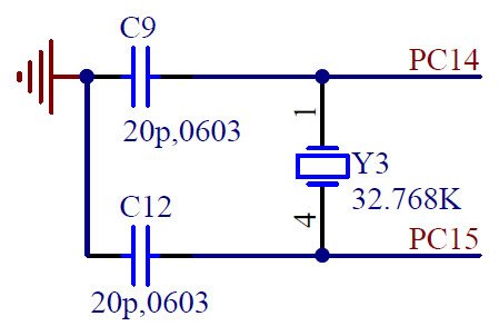
- LSE is a low-speed external clock connected to 32.768 kHz quartz crystal. The low-speed external oscillator can be used with external quartz or resonator, or with an external clock source in Bypass mode. The oscillator driving capability is programmable. Four modes are available, from an ultra-low power mode with a consumption of only 250 nano amperes to a high-driving mode. A clock security system monitors for the failure of the LSE oscillator. If LSE is used as a system clock, and a failure of the LSE clock is detected, the system clock switches automatically to LSI. The CSS is functional in all modes except Shutdown and VBAT. It is also functional under reset. The LSE can be used to clock the RTC, the CEC, the USARTs or low-power UART peripherals, and the low-power timers.
We do not mention HSI or other oscillators because they are not used with RTC.
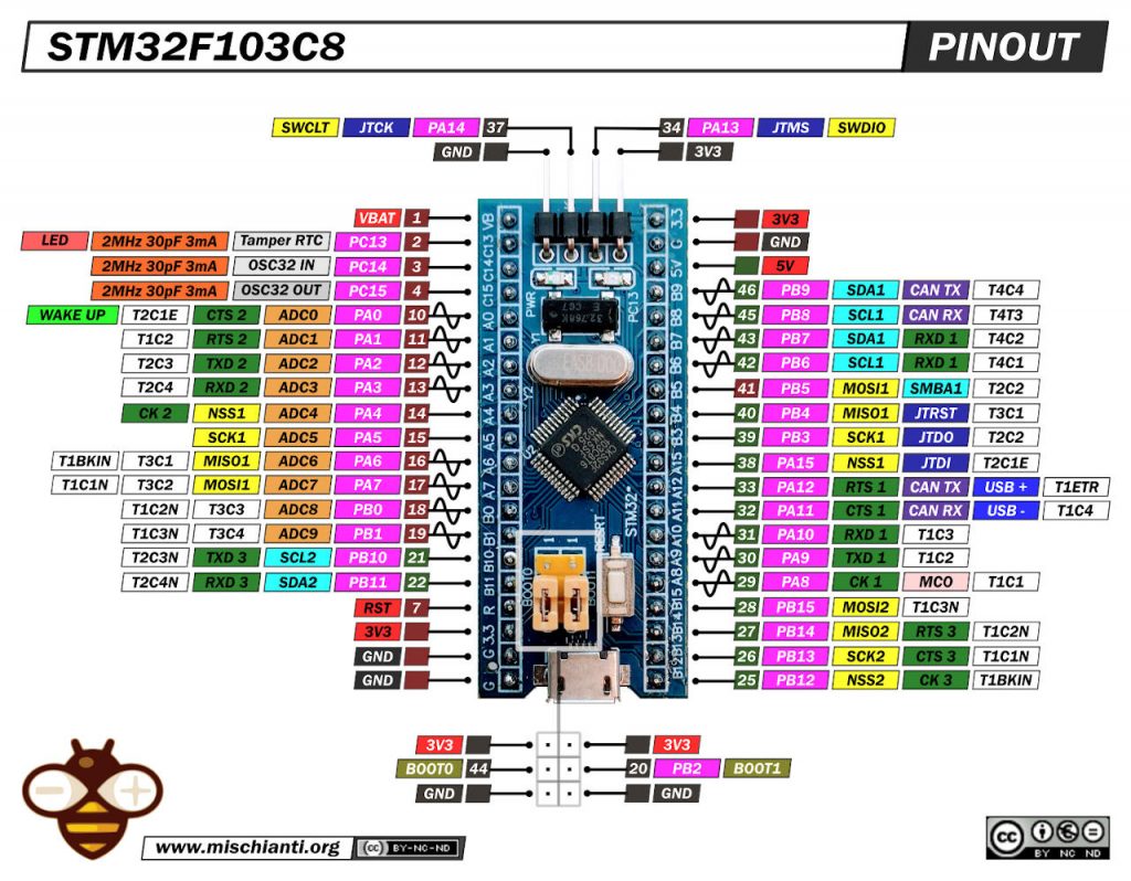
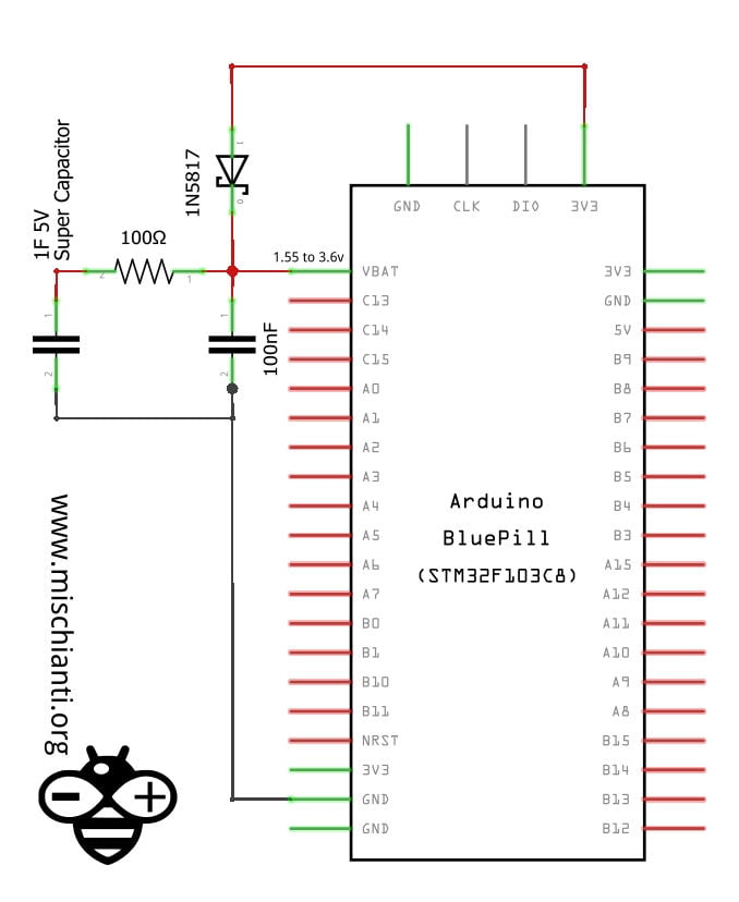
We are going to use for the test a generic STM32F103 blue pill (STM32F4 black pill is quite similar, only CPU freq change), and you can see in the schematic shared on the specified device that has a 4-to-16 MHz crystal oscillator internally connected to PD0 and PD1 to manage HSE.
And a 32 kHz oscillator for RTC with calibration connected to PC14 and PC15 is used for LSE.
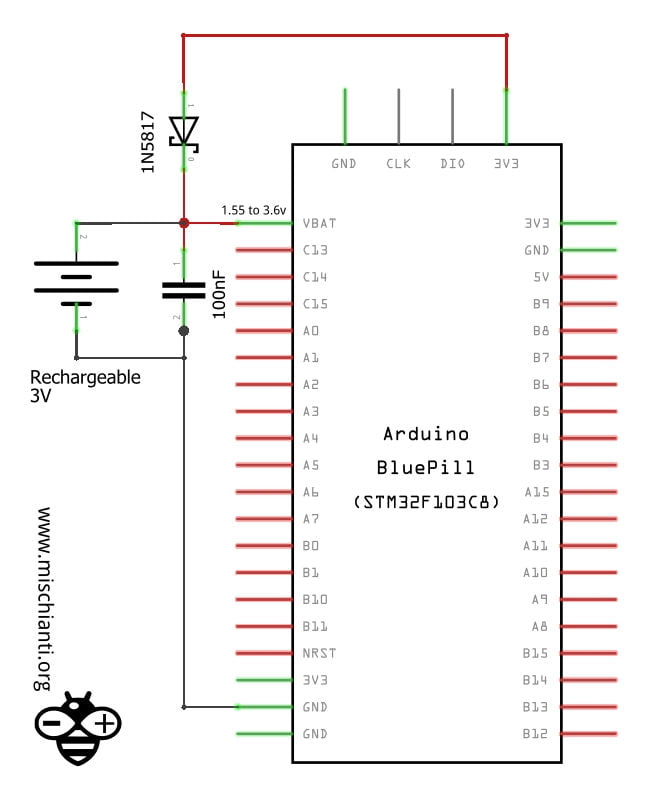
So the complete schema becomes.
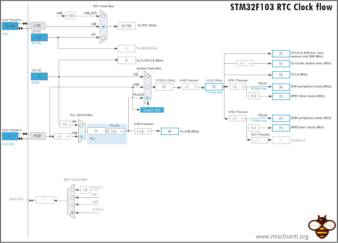
You can see an HSI RC also, but we must pay attention only to the RTC part of the schema.
Battery backup
As you can see in the pinout diagram, there is a VBAT pin.
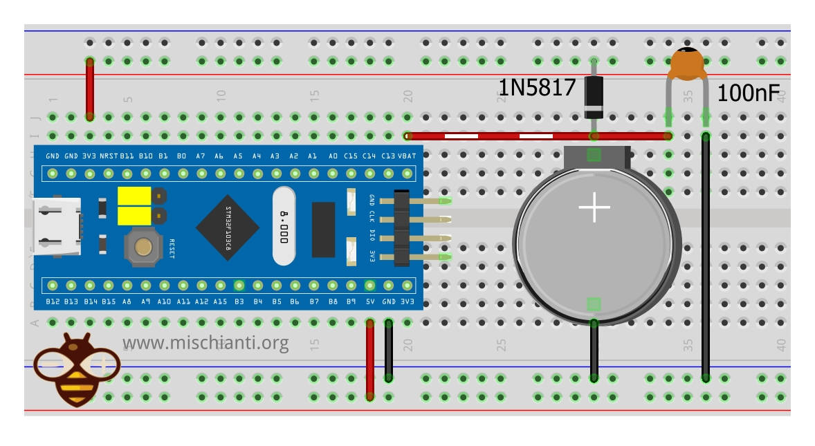
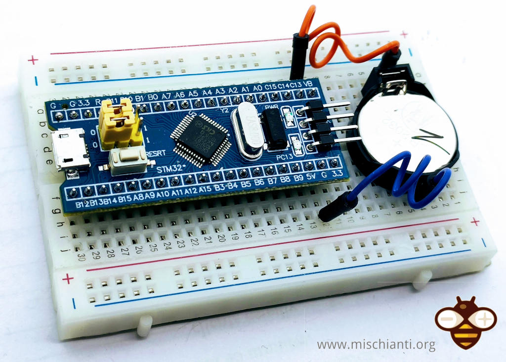
Normal battery
The simplest method to preserve the RTC status is to connect directly to a cr2032 battery.
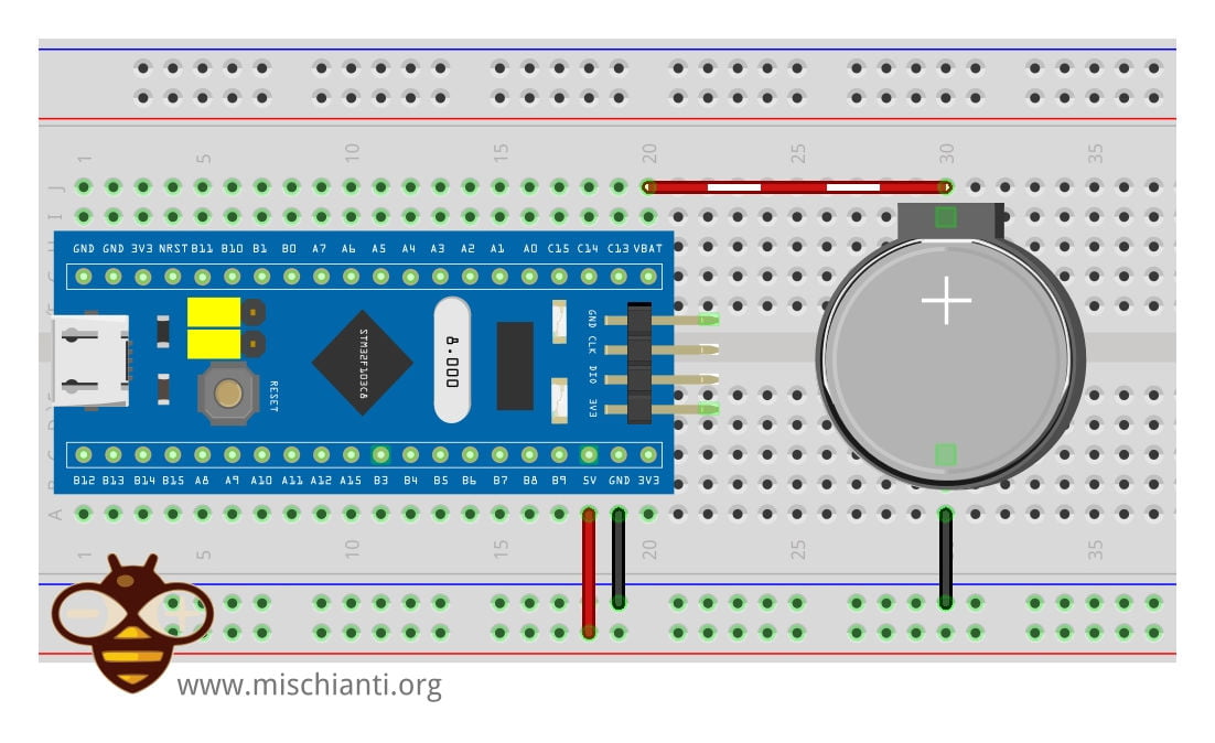
Pay attention that the cr2032 has 3.6v, so if you are going to use a LIR2032, remember that It has 4.2v at max charge, and It isn’t a good idea.
Select cr2032 5.5V Super Capacitor - ML2032 - cr2032 - Rechargeable AA and AAA
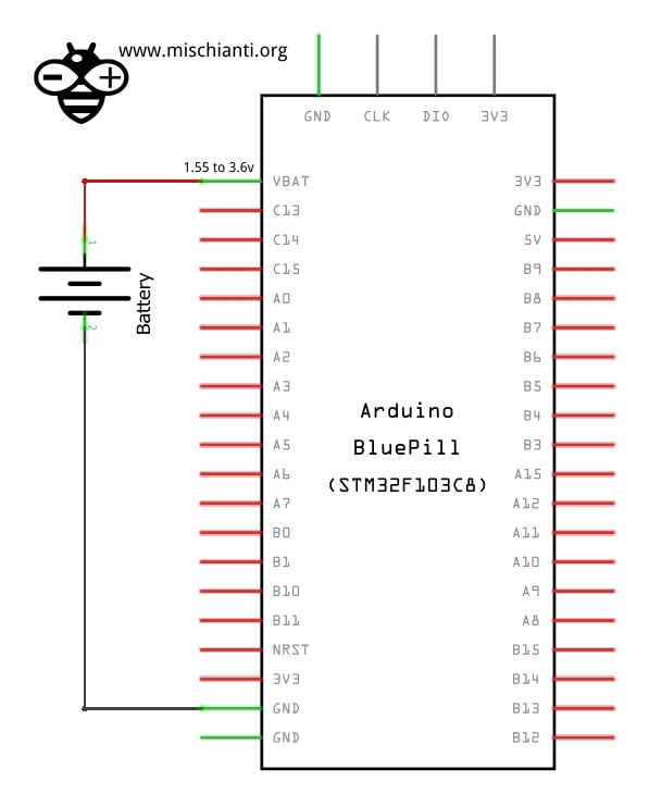
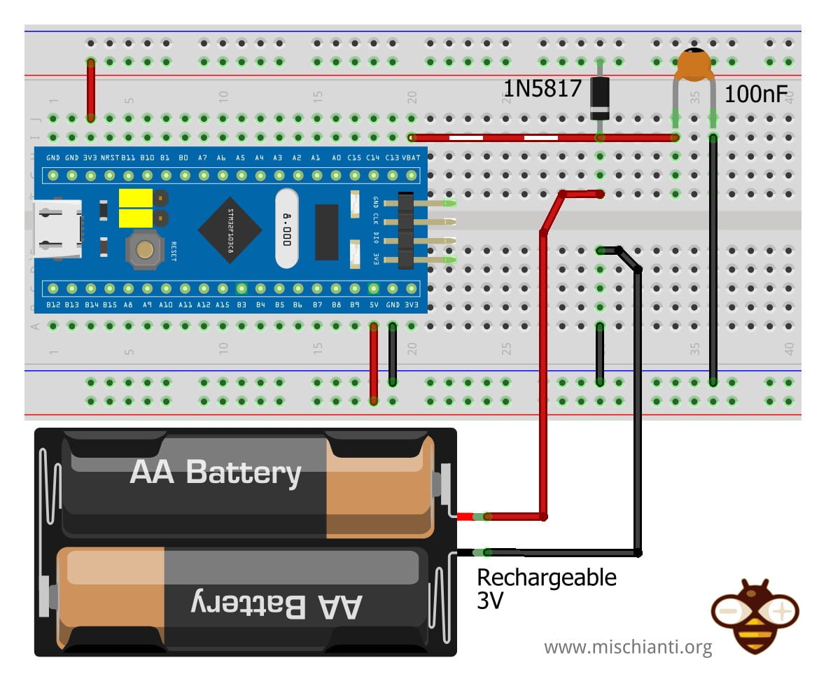
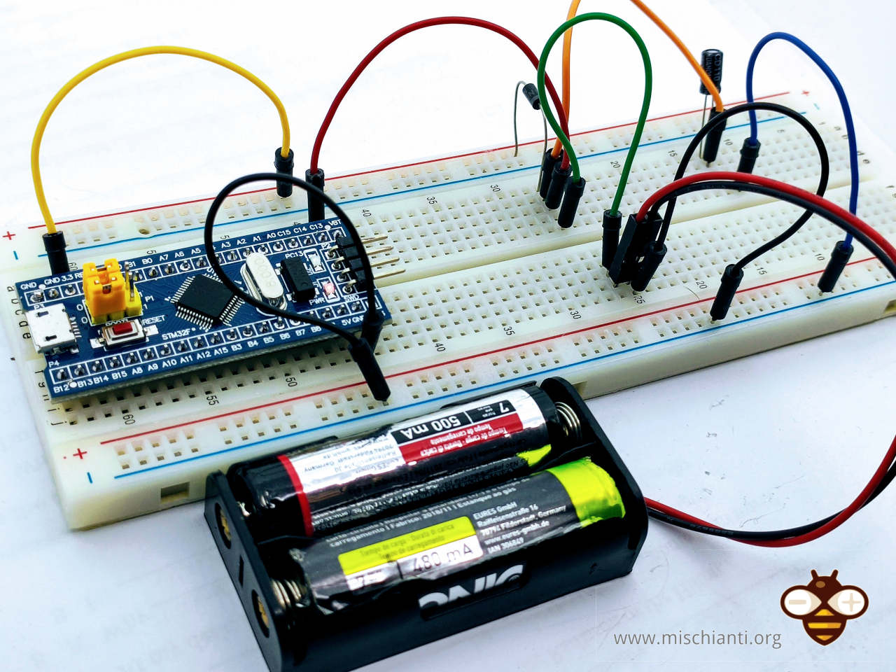
You can also use a 2xAA battery or similar, and the accepted range is 1.55v to 3.6v.
Rechargeable battery
Another good solution is to use a rechargeable battery (NiMH, NiCd, Li-ion, or Lipo cells), you can also provide a recharge system like the schema given by ST.
The NiMH AA battery can be a solution.
But I think the AA is quite big, so you can use an ML2032, a rechargeable battery at 3v that works from 3.2v to 2.6v.
As you can understand, the size and the amperage of the battery depend on your needs, like duration and package size.
Select ml2032 and Rechargeable AA and AAA 5.5V Super Capacitor - ML2032 - cr2032 - Rechargeable AA and AAA
Super-capacitor
Another good solution is the classic super-capacitor.
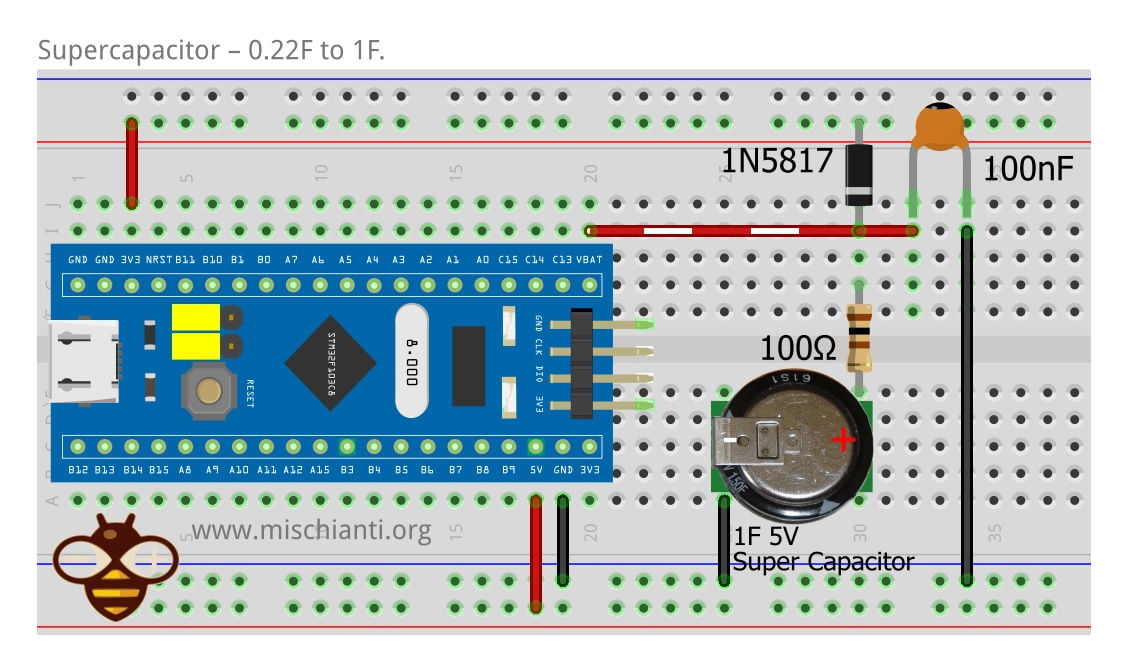
the ST advises a capacitor from 0.22F to 1F.
Select the super-capacitor 5.5V Super Capacitor - ML2032 - cr2032 - Rechargeable AA and AAA
Library
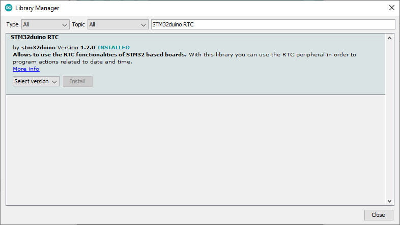
To interface the internal clock we can use the STM32RTC library, which offers a good quantity of functions.
And you can download It from the Arduino library manager.
Basic sketch
We use the default LSI without going in deep with the other modality, but paying attention to the schema, becomes very important when managing low-power management.
/**
 * Simple example of RTC Clock for STM32
 * You can use Serial to pass an epoch time that
 * synchronize the clock
 *
 * To generate epoch you can use browser console and input
 * Math.round(new Date().getTime()/1000)
 *
 * @author  Renzo Mischianti (www.mischianti.org)
 * @brief
 * @version 0.1
 * @date 2022-04-06
 *
 */
#include <Arduino.h>
#include <STM32RTC.h>

/* Get the rtc object */
STM32RTC& rtc = STM32RTC::getInstance();

/* Change these values to set the current initial time */
const byte seconds = 0;
const byte minutes = 0;
const byte hours = 16;

/* Change these values to set the current initial date */
/* Monday 15th June 2015 */
const byte weekDay = 1;
const byte day = 15;
const byte month = 6;
const byte year = 15;

void setup()
{
  Serial.begin(115200);

  // Select RTC clock source: LSI_CLOCK, LSE_CLOCK or HSE_CLOCK.
  // By default the LSI is selected as source.
  //rtc.setClockSource(STM32RTC::LSE_CLOCK);

  rtc.begin(); // initialize RTC 24H format

  // // Set the time
  // rtc.setHours(hours);
  // rtc.setMinutes(minutes);
  // rtc.setSeconds(seconds);

  // // Set the date
  // rtc.setWeekDay(weekDay);
  // rtc.setDay(day);
  // rtc.setMonth(month);
  // rtc.setYear(year);

  // // you can use also
  // //rtc.setTime(hours, minutes, seconds);
  // //rtc.setDate(weekDay, day, month, year);
}

long startTime = millis();
long interval = 5000;

void loop()
{
  if (startTime+interval<millis()){
    // Print date...
    Serial.printf("%02d/%02d/%02d ", rtc.getDay(), rtc.getMonth(), rtc.getYear());

    // ...and time
    Serial.printf("%02d:%02d:%02d.%03d\n", rtc.getHours(), rtc.getMinutes(), rtc.getSeconds(), rtc.getSubSeconds());
    startTime = millis();
  }
  if (Serial.available()){
    long epoch =  String(Serial.readString()).toInt();
    rtc.setEpoch(epoch);
    Serial.println(epoch);
  }
}
Here is the Serial output.
01/01/00 00:00:42.000
01/01/00 00:00:47.000
01/01/00 00:00:52.000
01/01/00 00:00:57.000
01/01/00 00:01:02.000
01/01/00 00:01:07.000

>>Send to COM35: "1649312899"<<
1649312899
07/04/22 06:28:19.000
07/04/22 06:28:24.000
07/04/22 06:28:29.000
07/04/22 06:28:34.000
07/04/22 06:28:39.000
If you disconnect the programmer cable and USB without disconnecting the backup battery, reconnect all and examine the output; you can check that the time was preserved.
Sketch: manage alarm
The STM32 provide a set of registers to store alarm and manage interrupt, we are going to examine a simple alarm.
/**
 * A simple sketch that set the time to
 * 2022-04-20 at 16:00:00
 * and an alarm at
 * 16:00:10
 * the result is the interrupt after 10 secs
 *
 * @author Renzo Mischianti <www.mischianti.org>
 * @version 0.1
 * @date 2022-04-07
 *
 * @copyright Copyright (c) 2022
 *
 */

#include <STM32RTC.h>

/* Get the rtc object */
STM32RTC& rtc = STM32RTC::getInstance();

/* Change these values to set the current initial time */
const byte seconds = 0;
const byte minutes = 0;
const byte hours = 16;

/* Change these values to set the current initial date */
const byte day = 20;
const byte month = 4;
const byte year = 22;

void alarmMatch(void *data);

void setup()
{
  Serial.begin(115200);

  // Select RTC clock source: LSI_CLOCK, LSE_CLOCK or HSE_CLOCK.
  // By default the LSI is selected as source.
  //rtc.setClockSource(STM32RTC::LSE_CLOCK);

  rtc.begin(); // initialize RTC 24H format

  // we set the time at 2022-04-20 at 16:00:00
  rtc.setTime(hours, minutes, seconds);
  rtc.setDate(day, month, year);

  rtc.attachInterrupt(alarmMatch);
  rtc.setAlarmDay(day);

  // Now we set an alert at 16:00:10
  // pratically 10 secs after the start
  // (check the initialization of clock)
  rtc.setAlarmTime(16, 0, 10, 0);
  rtc.enableAlarm(rtc.MATCH_DHHMMSS);
}

void loop()
{
  // Print date...
  Serial.printf("%02d/%02d/%02d ", rtc.getDay(), rtc.getMonth(), rtc.getYear());

  // ...and time
  Serial.printf("%02d:%02d:%02d.%03d\n", rtc.getHours(), rtc.getMinutes(), rtc.getSeconds(), rtc.getSubSeconds());
  delay(1000);
}

void alarmMatch(void *data)
{
  UNUSED(data);
  Serial.println("Alarm Match!");
}
And here is the Serial output.
20/04/22 16:00:05.000
20/04/22 16:00:06.000
20/04/22 16:00:07.000
20/04/22 16:00:08.000
20/04/22 16:00:09.000
20/04/22 16:00:10.000
Alarm Match!
20/04/22 16:00:11.000
20/04/22 16:00:12.000
20/04/22 16:00:13.000
20/04/22 16:00:14.000
20/04/22 16:00:15.000
20/04/22 16:00:16.000
20/04/22 16:00:17.000
Thanks
- STM32F1 Blue-Pill: pinout, specs, and Arduino IDE configuration (STM32duino and STMicroelectronics)
- STM32: program (STM32F1) via USB with STM32duino bootloader
- STM32: programming (STM32F1 STM32F4) via USB with HID boot-loader
- STM32F4 Black-Pill: pinout, specs, and Arduino IDE configuration
- STM32: ethernet w5500 with plain HTTP and SSL (HTTPS)
- STM32: ethernet enc28j60 with plain HTTP and SSL (HTTPS)
- STM32: WiFiNINA with ESP32 WiFi Co-Processor
- How to use SD card with stm32 and SdFat library
- \STM32: SPI flash memory FAT FS
- STM32: internal RTC, clock, and battery backup (VBAT)
- STM32 LoRa
- STM32 Power saving
- STM32F1 Blue-Pill clock and frequency management
- STM32F4 Black-Pill clock and frequency management
- Intro and Arduino vs STM framework
- Library LowPower, wiring, and Idle (STM Sleep) mode
- Sleep, deep sleep, shutdown, and power consumption
- Wake up from RTC alarm and Serial
- Wake up from the external source
- Backup domain intro and variable preservation across reset
- RTC backup register and SRAM preservation
- STM32 send emails with attachments and SSL (like Gmail): w5500, enc28j60, SD, and SPI Fash
- FTP server on STM32 with w5500, enc28j60, SD Card, and SPI Flash
- Connecting the EByte E70 to STM32 (black/blue pill) devices and a simple sketch example


I need this but programmed in STM32IDE using C. I dont know where to see the output anyways..
Hi Ian,
sorry I develop with the Arduino environment, the output It’s the standard Serial interface (I set It on USB connector).
You can find more info here
STM32F1: pinout, specs, and Arduino IDE configuration (STM32duino and STMicroelectronics) – 1
Bye Renzo
How to catch pulses while powered by coin cell – vbat. If main power vdd fails and vbat is available. Is it possible still to count pulses from some pin low frekvecy counts like 10hz ? store to memory backup memory etc.
Hi pr1,
I think you can use only the battery backup domain to preserve data, but no other operation. Some additional information about that in this article.
STM32 power saving: backup domain intro and variable preservation across reset – 8
Bye Renzo
But you leave the ml2032 always in charge without a circuit that cut off charge when its full charged? Its not a problem always in charge??
Hi Gabriele,
I didn’t check It, but the specifications from STM don’t say anything about that, so I think there isn’t a problem.
Bye Renzo