
ABB Aurora PV inverter library for Arduino, esp8266 and esp32
ABB Aurora protocol
Here the base information of RS485 ABB Aurora communication Protocol.
The communication between Host and processor works via a Serial Interface RS485 or RS232.
Configuration parameters in both cases are:
- 19200 baud (default value)
- 1 stop bit
- no parity
The communication protocol uses fixed length transmission messages (8Bytes + 2Bytes for Checksum) structured as follows:
| 0 | 1 | 2 | 3 | 4 | 5 | 6 | 7 | 8 | 9 |
| Address | Command | B2 | B3 | B4 | B5 | B6 | B7 | CRC_L | CRC_H |
Also the structure of the answer has fixed length (6 Bytes + 2 Bytes for Checksum) :
| 0 | 1 | 2 | 3 | 4 | 5 | 6 | 7 |
| Transmission State | Global State | B2 | B3 | B4 | B5 | CRC_L | CRC_H |
Transmission State is coded as follows:
0 = Everything is OK.
51 = Command is not implemented
52 = Variable does not exist
53 = Variable value is out of range
54 = EEprom not accessible
55 = Not Toggled Service Mode
56 = Can not send the command to internal micro
57 = Command not Executed
58 = The variable is not available, retry
Global State shows the state of the addressed device, the details are specified in the description of the commands.
I create this library to develop this Web Monitor interface.
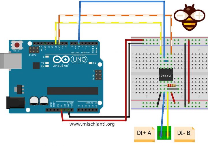
Arduino UNO and MAX485
You can use an Arduino UNO and a MAX485 IC, if you prefer can buy a module.
You can find IC on AliExpress
You can find module on AliExpress
You can ArduinoUNO on Arduino UNO - Arduino MEGA 2560 R3 - Arduino Nano - Arduino Pro Mini
Here the simple connection schema, the resistor must be 120Ω, i use 104Ω.
I create a library derived from a project that you can find in the web created by drhack, It’s a fantastic works (thanks to drhack) but I find It quite difficult to use, with specific hardware and not so reusable.
So I try to standardize the library and made It simple (the people that use my library know that “simplify first” It’s my motto.
esp8266 and MAX3485
If you want use an esp8266 (I create a centraline with Wemos D1 mini) you must buy a MAX3485 tha work at the correct voltage.
You can find IC on AliExpress
You can find module on AliExpressAliExpress
You can find WeMos D1 mini on WeMos D1 mini - NodeMCU V2 V2.1 V3 - esp01 - esp01 programmer
Here the simple connection schema, the resistor must be 120Ω, i use 104Ω.
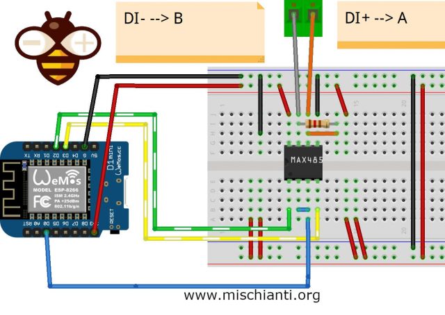
As you can see It’s quite simple to connect.
Library
You can find my library here.
To download.
- Click the DOWNLOADS button in the top right corner, rename the uncompressed folder ABB_Aurora_Solar_Inverter_Library.
- Check that the ABB_Aurora_Solar_Inverter_Library folder contains Aurora.cpp and Aurora.h.
- Place the ABB_Aurora_Solar_Inverter_Library library folder your /libraries/ folder.
- You may need to create the libraries subfolder if its your first library.
- Restart the IDE.
List of commands It’s quite big, so I’m going to explain all.
Constructor
As usual I try to create It more generic as possible, so If you want use HardwareSerial or SoftwareSerial you are free to choiche.
As you can see in the packet description
| 0 | 1 | 2 | 3 | 4 | 5 | 6 | 7 | 8 | 9 |
| Address | Command | B2 | B3 | B4 | B5 | B6 | B7 | CRC_L | CRC_H |
you must specify an address, that address normally is 2, but you must check It in your inverter menu.
You can create a chain of inverters that communicate via RS485. An address can be chosen from 2 to 63. The address on the inverter is set through the display and the pushbutton panel.
To change address go to SETTINGS --> Insert password (default 0000) --> Address.
This menu allows you to set the serial port addresses of the individual inverters connected to the RS485 line.
The addresses that can be assigned are 2 to 63. The UP and DOWN buttons scroll through the numerical scale. ‘AUTO’ selection cannot be used at present.
HardwareSerial
// Aurora(byte inverterAddress, HardwareSerial* serial, byte serialCommunicationControlPin)
Aurora inverter = Aurora(2, &Serial, 5);
inverterAddress: as described is the inverter address set on device.serial: is theHardwareSerial.serialCommunicationControlPin: is the pin that activate transmission of serial communication.
SoftwareSerial
// Aurora(byte inverterAddress, byte rxPin, byte txPin, byte serialCommunicationControlPin)
Aurora inverter = Aurora(2, 10, 11, 5);
inverterAddress: as described is the inverter address set on device.rxPin:is the SoftwareSerial RX pin.txPin:is the SoftwareSerial TX pin.serialCommunicationControlPin: is the pin that activate transmission of serial communication.
For software serial you can pass external SoftwareSerial instance.
// Aurora(byte inverterAddress, SoftwareSerial* serial, byte serialCommunicationControlPin)
How to
First you must startup the communication with begin command:
inverter.begin();
Than there are a lot of command that you can use to make query to your Inverter:
Inverter state request
First important command is readState to get the state of your Inverter:
Aurora::DataState dataState = inverter.readState();
The structure result have 4 attribute and 4 function:
            byte inverterState;
            byte channel1State;
            byte channel2State;
            byte alarmState;
            String getDcDcChannel1State()
            String getDcDcChannel2State()
            String getInverterState()
            String getAlarmState()
Naturally the attribute are the code, the function is the description of the state.
Inverter version
This command get the version of the inverter software:
Aurora::DataVersion dataVersion = inverter.readVersion();
The structure result have 4 attribute and 6 function:
            char par1;
            char par2;
            char par3;
            char par4;
            InverterModel getModelName()
            String getIndoorOutdoorAndType()
            String getGridStandard()
            String getGridStandardInt()
            String getTrafoOrNonTrafo()
            String getWindOrPV()
InverterModel have this structure:
    int ID;
    float multipler;
    String name;
par1 identify the model, and so I can create 2 description function one with the specific model, the second the type of the model;
par2 identify the grid standard and I create 2 function to get the grid standard that change in some part;
par3 specify if It’s trasformer less;
par4 specify if It’s Wind or PV version
Measure request to the DSP
With this command you can get the voltage, current etc.. etc.. there is a big list of parameter that I convert in a list of constant that you can use.
#define DSP_GRID_VOLTAGE_ALL								1   /* Grid Voltage (All) */
#define DSP_GRID_CURRENT_ALL								2   /* Grid Currrent (All) */
#define DSP_GRID_POWER_ALL									3   /* Grid Power (All) */
#define DSP_FREQUENCY_ALL									4   /* Frequency All) */
#define DSP_VBULK_WAS_ILEAK_DCDC_READING_ALL				5   /* VBulk was Ileak (Dc/Dc) reading All) */
#define DSP_ILEAK_DCDC_WAS_ILEAK_INVERTER_READING			6   /* Ileak (Dc/Dc) was Ileak (Inverter) Reading*/
#define DSP_ILEAK_INVERTER									7   /* Ileak (Inverter) */
#define DSP_PIN1_ALL										8   /* Pin 1 (All) */
#define DSP_PIN2											9   /* Pin 2 */
#define DSP_INVERTER_TEMPERATURE_GT							21  /* Inverter Temperature (Grid-Tied) */
#define DSP_BOOSTER_TEMPERATURE_GT							22  /* Booster Temperatuer (Grid-Tied) */
#define DSP_VOLTAGE_ALL										23  /* Input 1 Voltage */
#define DSP_CURRENT_ALL 									25  /* Input 1 Current (All) */
#define DSP_VOLTAGE_GT										26  /* Input 2 Voltage (Grid-Tied) */
#define DSP_CURRENT_GT										27  /* Input 2 Current (Grid-Tied) */
#define DSP_GRID_VOLTAGE_DCDC_GT							28  /* Grid Voltage (Dc/Dc) (Grid-Tied) */
#define DSP_GRID_FREQUENCY_DCDC_GT							29  /* Grid Frequency (Dc/Dc) (Grid-Tied) */
#define DSP_ISOLATION_RESISTANCE_RISO_ALL					30  /* Isolation Resistance (Riso) (All) */
#define DSP_VBULK_DCDC_GT									31  /* Vbulk (Dc/Dc) (Grid-Tied) */
#define DSP_AVERAGE_GRID_VOLTAGE_VGRIDAVG_GT				32  /* Average Grid Voltage (VgridAvg) (Grid-Tied) */
#define DSP_VBULKMID_GT										33  /* Vbulk Mid (Grid-Tied) */
#define DSP_POWER_PEAK_ALL									34  /* Power Peak (All) */
#define DSP_POWER_PEAK_TODAY_ALL							35  /* Power Peak Today (All) */
#define DSP_GRID_VOLTAGE_NEUTRAL_GT							36  /* Grid Voltage neutral (Grid-Tied) */
#define DSP_WIND_GENERATOR_FREQUENCY						37  /* Wind Generator Frequency */
#define DSP_GRID_VOLTAGE_NEUTRAL_PHASE_CENTRAL				38  /* Grid Voltage neutral-phase (Central) */
#define DSP_GRID_CURRENT_PHASE_R_CENTRAL_3P					39  /* Grid Current phase r (Central & 3 Phase) */
#define DSP_GRID_CURRENT_PHASE_S_CENTRAL_3P					40  /* Grid Current phase s (Central & 3 Phase) */
#define DSP_GRID_CURRENT_PHASE_T_CENTRAL_3P					41  /* Grid Current phase t (Central & 3 Phase) */
#define DSP_FREQUENCY_PHASE_R_CENTRAL_3P					42  /* Frequency phase r (Central & 3 Phase) */
#define DSP_FREQUENCY_PHASE_S_CENTRAL_3P					43  /* Frequency phase s (Central & 3 Phase) */
#define DSP_FREQUENCY_PHASE_T_CENTRAL_3P					44  /* Frequency phase t (Central & 3 Phase) */
#define DSP_VBULK_PLUS_CENTRAL_3P							45  /* Vbulk + (Central & 3 Phase) */
#define DSP_VBULK_MINUS_CENTRAL								46  /* Vbulk - (Central) */
#define DSP_SUPERVISOR_TEMPERATURE_CENTRAL					47  /* Supervisor Temperature (Central) */
#define DSP_ALIM_TEMPERATURE_CENTRAL						48  /* Alim Temperature (Central) */
#define DSP_HEAT_SINK_TEMPERATURE_CENTRAL					49  /* Heak Sink Temperature (Central) */
#define DSP_TEMPERATURE_1_CENTRAL							50  /* Temperature 1 (Central) */
#define DSP_TEMPERATURE_2_CENTRAL							51  /* Temperature 2 (Central) */
#define DSP_TEMPERATURE_3_CENTRAL							52  /* Temperature 3 (Central) */
#define DSP_FAN_1_SPEED_CENTRAL								53  /* Fan 1 Speed (Central) */
#define DSP_FAN_2_SPEED_CENTRAL								54  /* Fan 2 Speed (Central) */
#define DSP_FAN_3_SPEED_CENTRAL								55  /* Fan 3 Speed (Central) */
#define DSP_FAN_4_SPEED_CENTRAL								56  /* Fan 4 Speed (Central) */
#define DSP_FAN_5_SPEED_CENTRAL								57  /* Fan 5 Speed (Central) */
#define DSP_POWER_SATURATION_LIMIT_DER_CENTRAL				58  /* Power Saturation limit (Der.) (Central) */
#define DSP_RIFERIMENTO_ANELLO_BULK_CENTRAL					59  /* Reference Ring Bulk (Central) */
#define DSP_VPANEL_MICRO_CENTRAL							60  /* Vpanel micro (Central) */
#define DSP_GRID_VOLTAGE_PHASE_R_CENTRAL_3P					61  /* Grid Voltage phase r (Central & 3 Phase) */
#define DSP_GRID_VOLTAGE_PHASE_S_CENTRAL_3P					62  /* Grid Voltage phase s (Central & 3 Phase) */
#define DSP_GRID_VOLTAGE_PHASE_T_CENTRAL_3P					63  /* Grid Voltage phase t (Central & 3 Phase) */
#define DSP_FAN1_SPEED_CENTRAL								95  /* Fan 1 Speed (rpm) (Central) */
#define DSP_FAN2_SPEED_RPM_CENTRAL								96  /* Fan 2 Speed (rpm) (Central) */
#define DSP_FAN3_SPEED_RPM_CENTRAL								97  /* Fan 3 Speed (rpm) (Central) */
#define DSP_FAN4_SPEED_RPM_CENTRAL								98  /* Fan 4 Speed (rpm) (Central) */
#define DSP_FAN5_SPEED_RPM_CENTRAL								99  /* Fan 5 Speed (rpm) (Central) */
#define DSP_FAN6_SPEED_RPM_CENTRAL								100 /* Fan 6 Speed (rpm) (Central) */
#define DSP_FAN7_SPEED_RPM_CENTRAL								101 /* Fan 7 Speed (rpm) (Central) */
The command is simple:
Aurora::DataDSP dataDSP = inverter.readDSP(byte type, byte global)
global
if 1 requires the Global Measurements (Only For a Master)
if 0 requires the Module Measurements (Master and Slave)
and the result structure is simple too:
            float value;
            OutcomeState state;
Where value is the value requested, with this measurement units:
| Voltages | V |
| Currents | A |
| Powers | W |
| Temperatures | °C |
the OutcomeState is the returning state that have this structure:
			byte transmissionState;
			byte globalState;
			bool readState;
			String getTransmissionState()
			String getGlobalState()
Where transmission state describe if the command is correctly spelled, the global state is the global state of the inverter, the readState is the state of the calling: true inverter respond false no.
Time/Date reading
Get the time set on Inverter in seconds and epochTime, and I add 2 function one that return the String of the time and another that return tm standard Arduino structure.
Aurora::DataTimeDate dataTimeDate = inverter.readTimeDate();
            unsigned long seconds;
            unsigned long epochTime;
            String getDateTimeString()
            tm getDateTime()
Last four alarms
This command returns the codes of the last four alarms, in form of a FIFO queue from the first
(AL1) to the last one (AL4).
When this command is used the queue is emptied (the four values are set to zero).
Aurora::DataLastFourAlarms dataLastFourAlarms = inverter.readLastFourAlarms()
returning structure
        	byte alarm1;
        	byte alarm2;
        	byte alarm3;
        	byte alarm4;

                String getAlarm1State()
                String getAlarm2State()
                String getAlarm3State()
                String getAlarm4State()
Junction Box – State Request
Check the parameter and state of junction box.
Aurora::DataJunctionBoxState dataJunctionBoxState = inverter.readJunctionBoxState(byte nj)
NJ: Junction Box Number
Here the structure result
        	JBoxState jBoxState;
        	bool fuseBurnt[21] = {false,false,false,false,false,false,false,false,false,false,false,false,false,false,false,false,false,false,false,false,false};
        	bool stringCurrentUnbalanced[11] = {false,false,false,false,false,false,false,false,false,false,false} ;
            OutcomeState state;
I add a JBoxState to simplify the reading, here the structure
        	bool burnFuseOnJBox;
        	bool jBoxOvertemperature;
        	bool jBoxOvervoltage;
        	bool unbalancedStringCurrent;
        	bool jBoxOvercurrent;
        	bool powerOff;
        	bool noCommunication;
        	bool jBoxNotCalibrated;
P/N Reading (Aurora inverters)
Read the inverter PN
Aurora::DataSystemPN dataSystemPN = inverter.readSystemPN()
return a simple structure
            String PN;
            bool readState;
Serial Number reading (Aurora inverters)
Aurora::DataSystemSerialNumber dataSystemSerialNumber = inverter.readSystemSerialNumber()
and here the returning structure
            String SerialNumber;
            bool readState;
Manufacturing Week and Year reading (Aurora inverters)
Aurora::DataManufacturingWeekYear dataManufacturingWeekYear = inverter.readManufacturingWeekYear()
and here the returning structure
            String Week;
            String Year;
            OutcomeState state;
Firmware release reading
Aurora::DataFirmwareRelease dataFirmwareRelease = inverter.readFirmwareRelease()
and here the returning structure
            String release;
            OutcomeState state;
Cumulated energy readings (Aurora grid-tied inverters only)
Read the cumulated energy of the parameter that you pass
Aurora::DataCumulatedEnergy dataCumulatedEnergy = inverter.readCumulatedEnergy(byte par)
here the parameter
#define CUMULATED_DAILY_ENERGY				0				/* Daily Energy */
#define CUMULATED_WEEKLY_ENERGY  			1				/* Weekly Energy */
#define CUMULATED_ENERGY_OF_LAST_7_DAYS  		2				/* Energy of last 7 days */
#define CUMULATED_MONTHLY_ENERGY  			3				/* Monthly Energy */
#define CUMULATED_YEARLY_ENERGY  			4				/* Yearly Energy */
#define CUMULATED_TOTAL_ENERGY_LIFETIME  		5				/* Total Energy (total lifetime) */
#define CUMULATED_PARTIAL_ENERGY_SINCE_RESET  	        6				/* Partial Energy (cumulated since reset) */
here the simple structure
            unsigned long energy;
            OutcomeState state;
System Configuration
Aurora::DataConfigStatus dataConfigStatus = inverter.readConfig()
here the simple structure
        	byte configStatus;
        	String getConfigStatus() {
				return getConfigFlagByParams(this->configStatus);
			}
        	OutcomeState state;
Aurora::DataTimeCounter dataTimeCounter = inverter.readTimeCounter(byte param)
here the parameter
#define	CT_TOTAL_RUN		0
#define CT_PARTIAL_RUN		1
#define CT_TOTAL_GRID		2
#define CT_RESET_PARTIAL	3

#define CT_TOTAL_RUN_DESC	"Total Running Time (Lifetime)"
#define CT_PARTIAL_RUN_DESC	"Partial Running Time (since reset)"
#define CT_TOTAL_GRID_DESC	"Total Time With Grid Connection"
#define CT_RESET_PARTIAL_DESC	"Reset of Partial (Time & Energy)"
here the returning structure
        	unsigned long upTimeInSec;
        	int * getSecondsInDateElements() {
        		return getSecondsInDateElementsByParams(this->upTimeInSec);
			}
        	OutcomeState state;
Example code
Here an example of reading via Arduino.
/*
 Test Arduino MAX485 Aurora ABB connection
 by Mischianti Renzo <https://mischianti.org>

 https://www.mischianti.org/
*/

#include "Arduino.h"
#include <Aurora.h>
#include <SoftwareSerial.h>
#include <MemoryFree.h>

//SoftwareSerial mySerial(10, 11); // RX, TX
//Aurora inverter = Aurora(2, &Serial1, 5);
Aurora inverter = Aurora(2, 10, 11, 5);

void SerialPrintData(byte *data) {
  for (int i = 0; i < 8; i++) {
    Serial.print((int)data[i]);
    Serial.print(F(" "));
  }
  Serial.println(F(" "));

}

void setup()
{
	Serial.begin(19200);
	inverter.begin();
}

// The loop function is called in an endless loop
void loop()
{
	Serial.print(F("freeMemory(1)="));Serial.println(freeMemory());

	Aurora::DataCumulatedEnergy cumulatedEnergy = inverter.readCumulatedEnergy(CUMULATED_DAILY_ENERGY);
    Serial.println(F("------------------------------------------"));
    Serial.println(F("INVERTER 2"));
    Serial.print(F("          Data ROW = ")); SerialPrintData(inverter.receiveData);
    Serial.print(F("        Read State = ")); Serial.println(cumulatedEnergy.state.readState);
    Serial.print(F("Transmission State = ")); Serial.println(cumulatedEnergy.state.getTransmissionState());
    Serial.print(F("      Global State = ")); Serial.println(cumulatedEnergy.state.getGlobalState());
    Serial.print(F("           Energia = ")); Serial.print(cumulatedEnergy.energy); Serial.println(" Wh");
//    free(&cumulatedEnergy);
    Serial.println(F("------------------------------------------"));


	Aurora::DataLastFourAlarms lastFour = inverter.readLastFourAlarms();

    Serial.println(F("INVERTER 2"));
    Serial.print(F("          Data ROW = "));  SerialPrintData(inverter.receiveData);
	Serial.print(F("        Read State = "));  Serial.println(lastFour.state.readState);
    Serial.print(F("Transmission State = "));  Serial.println(lastFour.state.getTransmissionState());
    Serial.print(F("      Global State = "));  Serial.println(lastFour.state.getGlobalState());
    Serial.print(F("          Alarms 1 = "));  Serial.println(lastFour.getAlarm1State());
    Serial.print(F("          Alarms 2 = "));  Serial.println(lastFour.getAlarm2State());
    Serial.print(F("          Alarms 3 = "));  Serial.println(lastFour.getAlarm3State());
    Serial.print(F("          Alarms 4 = "));  Serial.println(lastFour.getAlarm4State());
//	free(&lastFour);

    Serial.println(F("------------------------------------------"));

    Aurora::DataVersion version = inverter.readVersion();
    Serial.println("INVERTER 2");
    Serial.print(F("          Data ROW = ")); SerialPrintData(inverter.receiveData);
    Serial.print(F("        Read State = ")); Serial.println(version.state.readState);
    Serial.print(F("Transmission State = ")); Serial.println(version.state.getTransmissionState());
    Serial.print(F("      Global State = ")); Serial.println(version.state.getGlobalState());
    Serial.print(F("           Version = ")); Serial.print(version.getModelName().name); Serial.print(F(" ")); Serial.print(version.getIndoorOutdoorAndType()); Serial.print(F(" ")); Serial.print(version.getGridStandard()); Serial.print(F(" ")); Serial.print(version.getTrafoOrNonTrafo()); Serial.print(F(" ")); Serial.println(version.getWindOrPV());
    Serial.println(F("------------------------------------------"));
//	free(&version);

    Aurora::DataConfigStatus configStatus = inverter.readConfig();

    Serial.print(F("          Data ROW = ")); SerialPrintData(inverter.receiveData);
    Serial.print(F("        Read State = ")); Serial.println(configStatus.state.readState);
    Serial.print(F("Transmission State = ")); Serial.println(configStatus.state.getTransmissionState());
    Serial.print(F("      Global State = ")); Serial.println(configStatus.state.getGlobalState());
    Serial.print(F("      config       = ")); Serial.println(configStatus.getConfigStatus());
    Serial.println(F("------------------------------------------"));
//	free(&version);
    Serial.print(F("freeMemory(2)="));Serial.println(freeMemory());

    Aurora::DataTimeCounter timeCounter = inverter.readTimeCounter(CT_TOTAL_RUN);

    Serial.print(F("          Data ROW = ")); SerialPrintData(inverter.receiveData);
    Serial.print(F("        Read State = ")); Serial.println(timeCounter.state.readState);
    Serial.print(F("Transmission State = ")); Serial.println(timeCounter.state.getTransmissionState());
    Serial.print(F("      Global State = ")); Serial.println(timeCounter.state.getGlobalState());
    Serial.print(F("      time in sec  = ")); Serial.println(timeCounter.upTimeInSec);
    Serial.print(F("      time in verb  = ")); Serial.print(timeCounter.getSecondsInDateElements()[0]); Serial.print(F("Y ")); Serial.print(timeCounter.getSecondsInDateElements()[1]); Serial.print(F("D "));Serial.print(timeCounter.getSecondsInDateElements()[2]);Serial.print(F("H "));Serial.print(timeCounter.getSecondsInDateElements()[3]);+Serial.print(F("M "));Serial.print(timeCounter.getSecondsInDateElements()[4]);Serial.println(F("S "));
    Serial.println(F("------------------------------------------"));
//	free(&version);
    Serial.print(F("freeMemory(2)="));Serial.println(freeMemory());

    delay(4000);

}
As you can see the usage is quite simple.
Video
Here the video of the result call.


Is it possible to control the output power (maximum) in real time with this?
Hi PVEVguy,
yes, in the lastest version of my Web monitor
Multilanguage Aurora Web Monito
I add a widget to get the update in realtime of the current power.
You can add a web socket service on esp8266 or esp32 and schedule the request every seconds or similar like the widget in the project.
Bye Renzo
Thanks a mill
Hi again Renzo,
Just in case we have not understood eachother correctly: I would like to limit the power output from the aurora inverter (not just check the output power of the inverter). I would like to be able to stop the inverter from exporting, or allow 1 kW output, or 1.5 kW etc. Is this possible?
Thanks,
PVEVguy
Hi PVEVguy,
Ahh! ok, sorry for the misunderstanding, no, It can’t manage that value.
Bye Renzo
Oops, I should have clarified before ordering the hardware 🙂 Do you think this functionality is possible in the Aurora with an alteration to the library? Or it is not possible at all? I know some inverters can do this, as they have a “zero export” functionality for grid code compliance.
Thanks,
PVEVguy
I check the documentation, but I think It isn’t possible.
Bye Renzo
Thanks
Hi Renzo, did you get a chance to check the documentation? Alternatively, could you send me a link to the Aurora inverter documentation you used, so that I can check. Thanks
I checked the documentation, but I didn’t find any solution.
I also add the link to the documentation.
Bye Renzo
Thanks for that Renzo
Thanks! This is what I was looking for. I have the components on order, and should be starting this in a couple weeks. I have two Aurora units.
Hi Jason,
if you want I develop a complete web monitor/logging solution.
ABB (ex Power One) Aurora Web Inverter Monitor (WIM): project introduction – 1
Bye Renzo
Hi, I see at the top of the reply’s someone asking about controlling the output power of the Aroura inverter. This document list commands to do that https://sicessolar.com.br/PDF/ABB/2.InversoresTrifasicos/2.5.TRIO-50/ApplicationNote/Modbus_RTU_register_map_for_TRIO-50%200-TL-OUTD_Revision_1%200.pdf
I would like to do the same I use these inverters for my offgrid power system and I need to control the power output to prevent battery over charging. I believe this is the required command to tell the inverter to reduce the power output to a percentage.
0210 1
Dynamic Mode
Active Power Set Point:
Active Power Curtailment
expressed as percentage of
Nominal Power in % steps
0 to 100 100 % U16
Must be used with Transient
configurations (Data
Address 0190, 0191, 0198)
Even if you tell me how to just send a the code required I can add it to the Arduino sketch I have that is monitoring my battery voltage. Then it can send the command to the Inverter.
If you can help it would be greatly appreciated. Thanks, Gary
Hi Four,
This version of Inverter uses Modbus and is another device type.
The library can be used only for the ex-PowerOne Aurora.
Bye Renzo
But how do you do it to have two inverters in series connected to each other? do I have to put two esp or can I declare 2 addresses? How do you do?
Hi Massimo,
if you mean with the library you instantiate 2 objects that point to a different address
using two connections, in parallel I’ve never checked but it would be
if you mean with the library you instantiate 2 objects that point to a different address
But I believe the second option can generate conflicts.
Hi RM