
Ebyte LoRa E220 LLCC68 device for Arduino, esp32 or esp8266: library – 2
LoRa or Long Range wireless data telemetry is a technology pioneered by Semtech that operates at a lower frequency than NRF24L01 (433 MHz, 868 MHz, or 916 MHz against 2.4 GHz for the NRF24L01) but at thrice the distance (from 5000m to 11000m).
LLCC68
LoRa Smart Home (LLCC68) is a sub-GHz LoRa® RF Transceiver for medium-range indoor and indoor to outdoor wireless applications. SPI interface. Pin-to-pin is compatible with SX1262. SX1261, SX1262, SX1268, and LLCC68 are designed for long battery life with just 4.2 mA of active receive current consumption. The SX1261 can transmit up to +15 dBm, and the SX1262, SX1268, and LLCC68 can transmit up to +22 dBm with highly efficient integrated power amplifiers.
These devices support LoRa modulation for LPWAN use cases and (G)FSK modulation for legacy use cases. The devices are highly configurable to meet different application requirements for consumer use. The device provides LoRa modulation compatible with Semtech transceivers used by the LoRaWAN® specification released by the LoRa Alliance®. The radio is suitable for systems targeting compliance with radio regulations, including but not limited to ETSI EN 300 220, FCC CFR 47 Part 15, China regulatory requirements, and the Japanese ARIB T-108. Continuous frequency coverage from 150MHz to 960MHz allows the support of all major sub-GHz ISM bands around the world.
Features
- The new LoRa spread spectrum modulation technology developed based on LLCC68, it brings a more extended communication distance and stronger anti-interference ability;
- Support users to set the communication key by themselves, and it cannot be read, which significantly improves the confidentiality of user data;
- Support LBT function, monitor the channel environment noise before sending, which significantly improves the communication success rate of the module in harsh environments;
- Support RSSI signal strength indicator function for evaluating signal quality, improving communication network, and ranging;
- Support air wakeup, that is ultra-low power consumption, suitable for battery-powered applications;
- Support point to point transmission, broadcast transmission, channel sense;
- Support deep sleep, the power consumption of the whole machine is about 5uA in this mode;
- The module has built-in PA+LNA, and the communication distance can reach 5km under ideal conditions;
- The parameters are saved after power-off, and the module will work according to the set parameters after power-on;
- Efficient watchdog design, once an exception occurs, the module will automatically restart and continue to work according to the previous parameter settings;
- Support the bit rate of2.4k~62.5kbps;
- Support 3.0~5.5V power supply, power supply greater than 5V can guarantee the best performance;
- Industrial standard design, supporting long-term use at -40~+85℃;
Comparison
| LLCC68 | SX1278-SX1276 | |
|---|---|---|
| Distance | > 11Km | 8Km |
| Rate (LoRa) | 1.76Kbps – 62.5Kbps | 0.3Kbps – 19.2Kbps |
| Sleep power consumption | 2µA | 5µA |
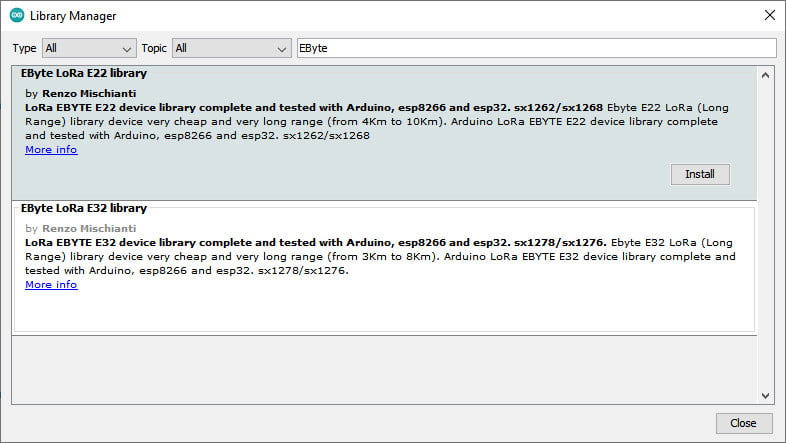
Library
You can find my library here, and It’s available on Arduino IDE library manager.
To download.
Click the DOWNLOADS button in the top right corner, rename the uncompressed folder LoRa_E220.
Check that the LoRa_E220 folder contains LoRa_E220.cpp and LoRa_E220.h.
Place the LoRa_E220 library folder in your /libraries/ folder.
You may need to create the libraries subfolder if it’s your first library.
Restart the IDE.
Pinout
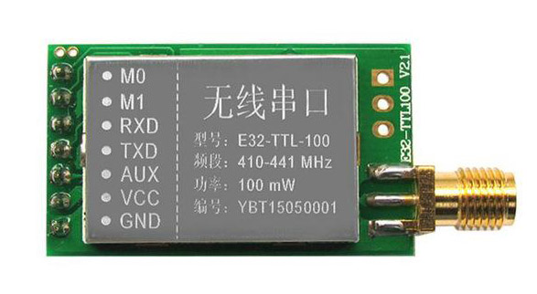
| Pin No. | Pin item | Pin direction | Pin application |
|---|---|---|---|
| 1 | M0 | Input(weak pull-up) | Work with M1 & decide the four operating modes. Floating is not allowed; it can be ground. |
| 2 | M1 | Input(weak pull-up) | Work with M0 & decide the four operating modes. Floating is not allowed; it can be ground. |
| 3 | RXD | Input | TTL UART inputs connect to external (MCU, PC) TXD output pin. It can be configured as open-drain or pull-up input. |
| 4 | TXD | Output | TTL UART outputs connect to external RXD (MCU, PC) input pin. Can be configured as open-drain or push-pull output |
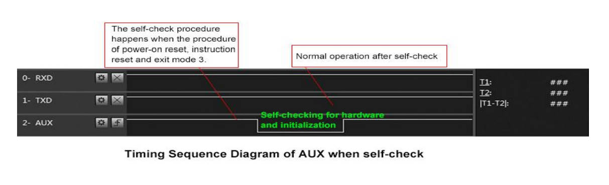
5 | AUX | Output | To indicate the module’s working status & wake up the external MCU. During the procedure of self-check initialization, the pin outputs a low level. It can be configured as open-drain or push-pull output (floating is allowed). |
| 6 | VCC | Power supply 3V~5.5V DC | |
| 7 | GND | Ground |
As you can see, you can set various modes via M0 and M1 pins.
| Mode | M1 | M0 | Explanation |
|---|---|---|---|
| Normal | 0 | 0 | UART and wireless channels are open, and transparent transmission is on |
| WOR Transmitter | 0 | 1 | WOR Transmitter |
| WOR Receiver | 1 | 0 | WOR Receiver (Supports wake up over air) |
| Deep sleep mode | 1 | 1 | The module goes to sleep (automatically wake up when configuring parameters) |
Some pins can be used statically, but If you connect them to the microcontroller and configure them in the library, you gain in performance and can control all modes via software. Still, we are going to explain better next.
Fully connected schema
As I already said, It’s not essential to connect all pins to the microcontroller’s output; you can put M0 and M1 pins to HIGH or LOW to get the desired configuration. If you don’t connect AUX, the library set a reasonable delay to ensure that the operation is complete (If you have trouble with the device freezing, you must put a pull-up 4.7k resistor or better connect to the device. ).
AUX pin
When transmitting data can be used to wake up external MCU and return HIGH on data transfer finish.
When receiving, AUX goes LOW and returns HIGH when the buffer is empty.
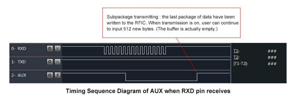
It’s also used for self-checking to restore regular operation (on power-on and sleep/program mode).
esp8266
esp8266 connection schema is more straightforward because it works at the same voltage of logical communications (3.3v).
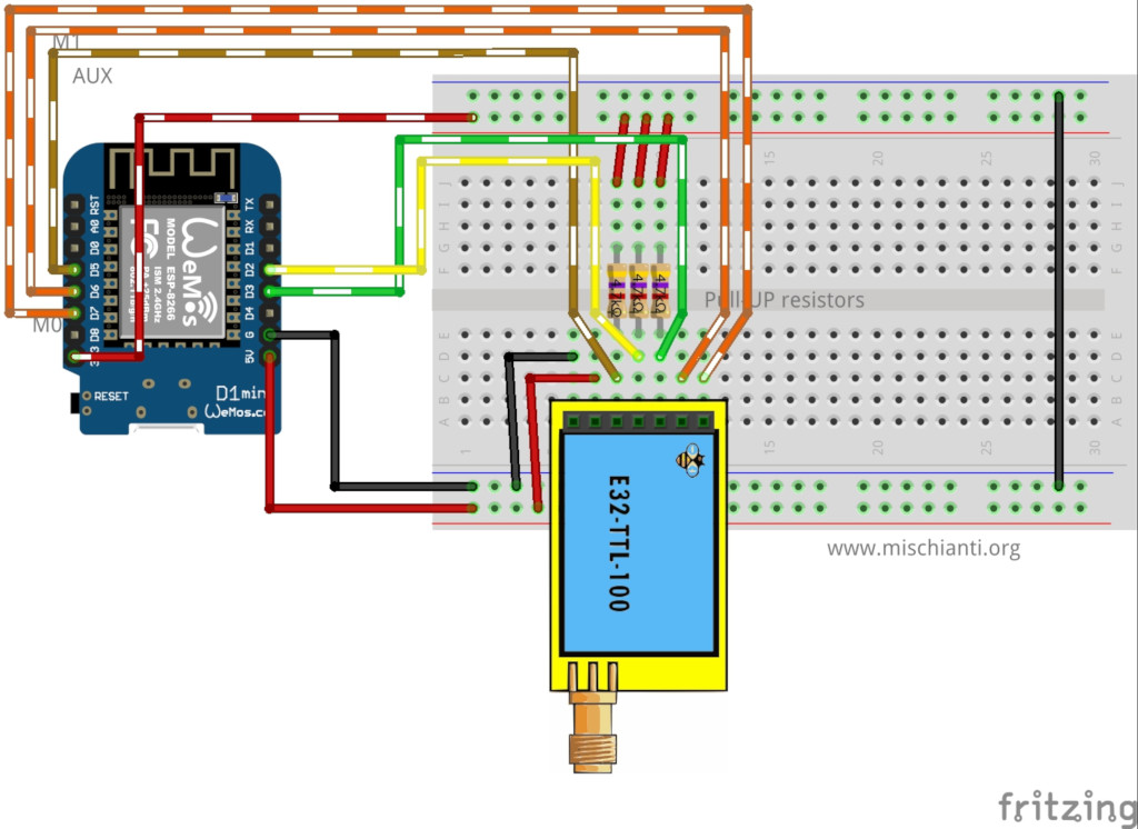
It’s essential to add a pull-up resistor (4,7Kohm) to get good stability.
| E220 | esp8266 |
|---|---|
| M0 | D7 |
| M1 | D6 |
| TX | PIN D2 (PullUP 4,7KΩ) |
| RX | PIN D3 (PullUP 4,7KΩ) |
| AUX | PIN D5 (PullUP 4,7KΩ) |
| VCC | 5V (but work with less power in 3.3v) |
| GND | GND |
esp32
Similar connection schema for esp32, but for RX and TX, we use RX2 and TX2 because, by default, esp32 doesn’t have SoftwareSerial but has 3 Serial.
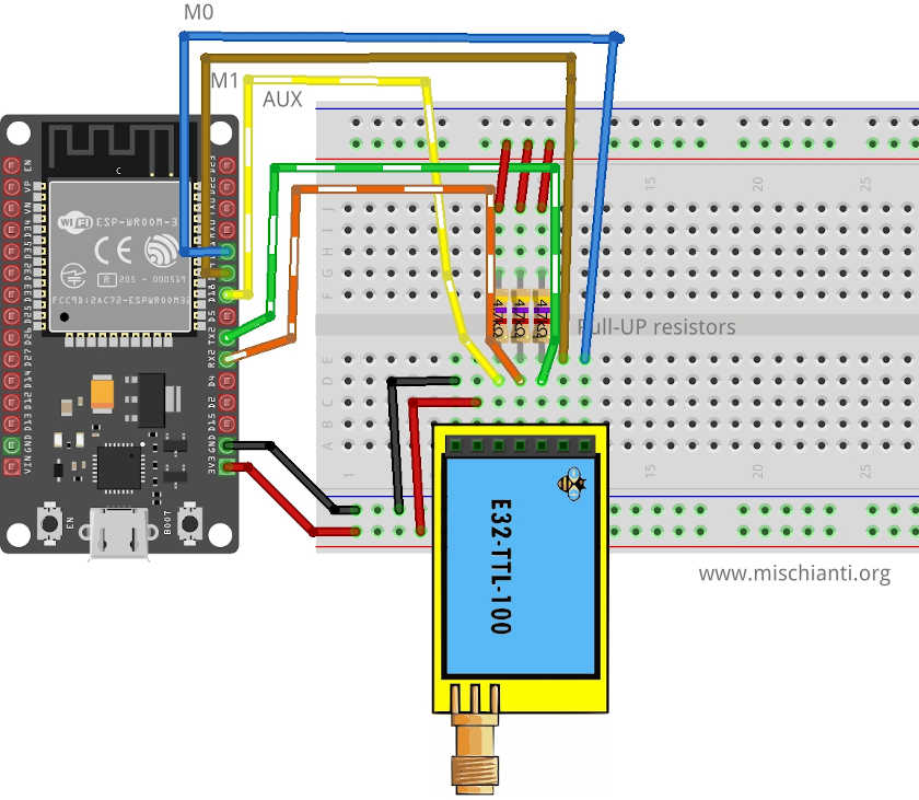
| E220 | esp32 |
|---|---|
| M0 | D21 |
| M1 | D19 |
| TX | PIN RX2 (PullUP 4,7KΩ) |
| RX | PIN TX3 (PullUP 4,7KΩ) |
| AUX | PIN D18 (PullUP 4,7KΩ) (D15 to wake up) |
| VCC | 5V (but work with less power in 3.3v) |
| GND | GND |
Arduino
Arduino’s working voltage is 5v, so we need to add a voltage divider on RX pin M0 and M1 of LoRa module to prevent damage; you can get more information here Voltage divider: calculator and application.
You can use a 2Kohm resistor to GND and 1Kohm from the signal, then put them together on RX.
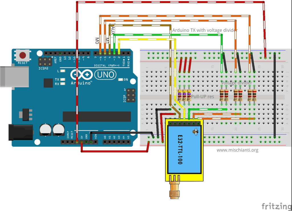
| M0 | 7 (voltage divider) |
| M1 | 6 (voltage divider) |
| TX | PIN 2 (PullUP 4,7KΩ) |
| RX | PIN 3 (PullUP 4,7KΩ & Voltage divider) |
| AUX | PIN 5 (PullUP 4,7KΩ) |
| VCC | 5V |
| GND | GND |
Arduino MKR WiFi 1010
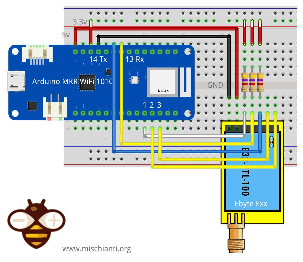
| M0 | 2 |
| M1 | 3 |
| TX | PIN 14 Tx (PullUP 4,7KΩ) |
| RX | PIN 13 Rx (PullUP 4,7KΩ) |
| AUX | PIN 1 (PullUP 4,7KΩ) |
| VCC | 5V |
| GND | GND |
Arduino Nano 33 IoT
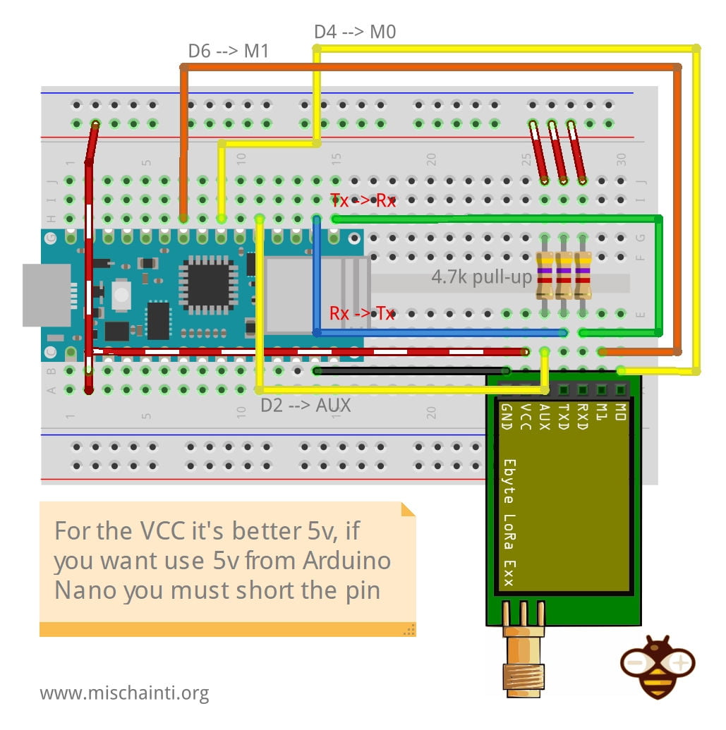
| M0 | 4 |
| M1 | 6 |
| RX | PIN PB23 Tx (PullUP 4,7KΩ) |
| TX | PIN PB22 Rx (PullUP 4,7KΩ) |
| AUX | PIN 2 (PullUP 4,7KΩ) |
| VCC | 5V |
| GND | GND |
// ------------- Arduino Nano 33 IoT -------------
// LoRa_E220 e220ttl(&Serial1, 2, 4, 6); //  RX AUX M0 M1
// -------------------------------------------------
Constructor
I made a set of numerous constructors because we can have more options and situations to manage.
		LoRa_E220(byte txE220pin, byte rxE220pin, UART_BPS_RATE bpsRate = UART_BPS_RATE_9600);
		LoRa_E220(byte txE220pin, byte rxE220pin, byte auxPin, UART_BPS_RATE bpsRate = UART_BPS_RATE_9600);
		LoRa_E220(byte txE220pin, byte rxE220pin, byte auxPin, byte m0Pin, byte m1Pin, UART_BPS_RATE bpsRate = UART_BPS_RATE_9600);
The first set of constructors is created to delegate Serial and other pins to the library.
txE220pinandrxE220pinare the pins to connect to UART. They are mandatory.auxPinis a pin that checks the operation, transmission, and receiving status (we are going to explain better next), that pin isn’t mandatory; if you don’t set It, I apply a delay to permit the operation to complete itself (with latency, if you have trouble, like freeze device, you must put a pull-up 4.7k resistor or better connect to the device ).m0pinandm1Pinare the pins to change operation MODE (see the table upper), I think this pins in “production” are going to connect directly HIGH or LOW. Still, for a test, they are helpful to be managed by the library.bpsRateis the baud rate of SoftwareSerial is typically 9600 (the only baud rate in programming/sleep mode)
A simple example is
#include "LoRa_E220.h"

LoRa_E220 e220ttl(2, 3);  // e220 TX e220 RX
// LoRa_E220 e220ttl(2, 3, 5, 6, 7);  // e220 TX e220 RX
We can use a SoftwareSerial directly with another constructor
		LoRa_E220(HardwareSerial* serial, UART_BPS_RATE bpsRate = UART_BPS_RATE_9600);
		LoRa_E220(HardwareSerial* serial, byte auxPin, UART_BPS_RATE bpsRate = UART_BPS_RATE_9600);
		LoRa_E220(HardwareSerial* serial, byte auxPin, byte m0Pin, byte m1Pin, UART_BPS_RATE bpsRate = UART_BPS_RATE_9600);
The example upper with this constructor can be done like so.
#include <SoftwareSerial.h>
#include "LoRa_E220.h"

SoftwareSerial mySerial(2, 3); // e220 TX e220 RX
LoRa_E220 e220ttl(&mySerial);
// LoRa_E220 e220ttl(&mySerial, 5, 7, 6);
The last set of constructors is to permit an HardwareSerial instead of SoftwareSerial.
		LoRa_E220(SoftwareSerial* serial, UART_BPS_RATE bpsRate = UART_BPS_RATE_9600);
		LoRa_E220(SoftwareSerial* serial, byte auxPin, UART_BPS_RATE bpsRate = UART_BPS_RATE_9600);
		LoRa_E220(SoftwareSerial* serial, byte auxPin, byte m0Pin, byte m1Pin, UART_BPS_RATE bpsRate = UART_BPS_RATE_9600);
For esp32, you have three additional constructors to permit to manage pins for HardWare serial.
			LoRa_E220(byte txE220pin, byte rxE220pin, HardwareSerial* serial, UART_BPS_RATE bpsRate = UART_BPS_RATE_9600, uint32_t serialConfig = SERIAL_8N1);
			LoRa_E220(byte txE220pin, byte rxE220pin, HardwareSerial* serial, byte auxPin, UART_BPS_RATE bpsRate = UART_BPS_RATE_9600, uint32_t serialConfig = SERIAL_8N1);
			LoRa_E220(byte txE220pin, byte rxE220pin, HardwareSerial* serial, byte auxPin, byte m0Pin, byte m1Pin, UART_BPS_RATE bpsRate = UART_BPS_RATE_9600, uint32_t serialConfig = SERIAL_8N1);
Begin
The begin command is used to startup Serial and pins in input and output mode.
void begin();
in execution is
	// Startup all pins and UART
	e220ttl.begin();
Configuration and method to get information
There are many methods for managing configuration and getting information about the device.
		ResponseStructContainer getConfiguration();
		ResponseStatus setConfiguration(Configuration configuration, PROGRAM_COMMAND saveType = WRITE_CFG_PWR_DWN_LOSE);

		ResponseStructContainer getModuleInformation();
        void printParameters(struct Configuration configuration);
        ResponseStatus resetModule();
Response containers
To simplify the management of response, I created a set of containers, which is very useful for managing errors and returning generic data.
ResponseStatus
The ResponseStatus is a status container and has two simple entry points, with this you can get the status code and the description of the status code
	Serial.println(c.getResponseDescription()); // Description of code
	Serial.println(c.code); // 1 if Success
The code is
  E220_SUCCESS = 1,
  ERR_E220_UNKNOWN,
  ERR_E220_NOT_SUPPORT,
  ERR_E220_NOT_IMPLEMENT,
  ERR_E220_NOT_INITIAL,
  ERR_E220_INVALID_PARAM,
  ERR_E220_DATA_SIZE_NOT_MATCH,
  ERR_E220_BUF_TOO_SMALL,
  ERR_E220_TIMEOUT,
  ERR_E220_HARDWARE,
  ERR_E220_HEAD_NOT_RECOGNIZED
ResponseContainer
This container is created to manage String response and has two entry points.
data with the string returned from the message and status an instance of RepsonseStatus.
		ResponseContainer rs = e220ttl.receiveMessage();
		String message = rs.data;

		Serial.println(rs.status.getResponseDescription());
		Serial.println(message);
But this command goes to read all the data in the buffer. If you receive three messages, you are going to read all three notes at one time, and my simple solution is to use an end character to send at the end of the message, to default I use \0 (null character)
		ResponseContainer rs = e220ttl.receiveMessageUntil();
                // You can specify a custom delimiter also
		// ResponseContainer rs = e220ttl.receiveMessageUntil('|');

		String message = rs.data;

		Serial.println(rs.status.getResponseDescription());
		Serial.println(message);
This version of the device support RSSI also. To read that parameter (if you specify in the configuration that you want to send also that), you can use
	    ResponseContainer rc = e220ttl.receiveMessageRSSI();
		String message = rs.data;

		Serial.println(rs.status.getResponseDescription());
		Serial.println(message);
        Serial.print("RSSI: "); Serial.println(rc.rssi, DEC);
ResponseStructContainer
The ResponseStructContainer is the more “complex” container. I use this to manage structures, It has the same entry points of ResponseContainer, but data is a void pointer to manage complex structure.
	ResponseStructContainer c;
	c = e220ttl.getConfiguration();
	// It's important get configuration pointer before all other operation
	Configuration configuration = *(Configuration*) c.data;
	Serial.println(c.status.getResponseDescription());
	Serial.println(c.status.code);
    c.close();
If you receive a structured message with RSSI, you can use
		ResponseStructContainer rsc = e220ttl.receiveMessageRSSI(sizeof(Message));
		Serial.println(rsc.status.getResponseDescription());
		struct Message message = *(Message*) rsc.data;
		Serial.println(message.type);
		Serial.println(message.message);
		Serial.println(*(float*)(message.temperature));
		Serial.print("RSSI: "); Serial.println(rsc.rssi, DEC);
        rsc.close();
Every time you use a ResponseStructContainer you must close It with close()
getConfiguration and setConfiguration
The first method is getConfiguration, and you can use It to retrieve all data stored on the device.
ResponseStructContainer getConfiguration();
Here is a usage example.
	ResponseStructContainer c;
	c = e220ttl.getConfiguration();
	// It's important get configuration pointer before all other operation
	Configuration configuration = *(Configuration*) c.data;
	Serial.println(c.status.getResponseDescription());
	Serial.println(c.status.code);
    Serial.println(configuration.SPED.getUARTBaudRate());
    c.close();
Structure of configuration have all data of settings, and I add a series of functions to get all description of single data.
	configuration.ADDL = 0x03;  // First part of address
	configuration.ADDH = 0x00; // Second part

	configuration.CHAN = 23; // Communication channel

	configuration.SPED.uartBaudRate = UART_BPS_9600; // Serial baud rate
	configuration.SPED.airDataRate = AIR_DATA_RATE_010_24; // Air baud rate
	configuration.SPED.uartParity = MODE_00_8N1; // Parity bit

	configuration.OPTION.subPacketSetting = SPS_200_00; // Packet size
	configuration.OPTION.RSSIAmbientNoise = RSSI_AMBIENT_NOISE_DISABLED; // Need to send special command
	configuration.OPTION.transmissionPower = POWER_22; // Device power

	configuration.TRANSMISSION_MODE.enableRSSI = RSSI_DISABLED; // Enable RSSI info
	configuration.TRANSMISSION_MODE.fixedTransmission = FT_TRANSPARENT_TRANSMISSION; // Enable repeater mode
	configuration.TRANSMISSION_MODE.enableLBT = LBT_DISABLED; // Check interference
	configuration.TRANSMISSION_MODE.WORPeriod = WOR_2000_011; // WOR timing
You have the equivalent function for all attributes to get all descriptions:
void printParameters(struct Configuration configuration) {
	Serial.println("----------------------------------------");

	Serial.print(F("HEAD : "));  Serial.print(configuration.COMMAND, HEX);Serial.print(" ");Serial.print(configuration.STARTING_ADDRESS, HEX);Serial.print(" ");Serial.println(configuration.LENGHT, HEX);
	Serial.println(F(" "));
	Serial.print(F("AddH : "));  Serial.println(configuration.ADDH, HEX);
	Serial.print(F("AddL : "));  Serial.println(configuration.ADDL, HEX);
	Serial.println(F(" "));
	Serial.print(F("Chan : "));  Serial.print(configuration.CHAN, DEC); Serial.print(" -> "); Serial.println(configuration.getChannelDescription());
	Serial.println(F(" "));
	Serial.print(F("SpeedParityBit     : "));  Serial.print(configuration.SPED.uartParity, BIN);Serial.print(" -> "); Serial.println(configuration.SPED.getUARTParityDescription());
	Serial.print(F("SpeedUARTDatte     : "));  Serial.print(configuration.SPED.uartBaudRate, BIN);Serial.print(" -> "); Serial.println(configuration.SPED.getUARTBaudRateDescription());
	Serial.print(F("SpeedAirDataRate   : "));  Serial.print(configuration.SPED.airDataRate, BIN);Serial.print(" -> "); Serial.println(configuration.SPED.getAirDataRateDescription());
	Serial.println(F(" "));
	Serial.print(F("OptionSubPacketSett: "));  Serial.print(configuration.OPTION.subPacketSetting, BIN);Serial.print(" -> "); Serial.println(configuration.OPTION.getSubPacketSetting());
	Serial.print(F("OptionTranPower    : "));  Serial.print(configuration.OPTION.transmissionPower, BIN);Serial.print(" -> "); Serial.println(configuration.OPTION.getTransmissionPowerDescription());
	Serial.print(F("OptionRSSIAmbientNo: "));  Serial.print(configuration.OPTION.RSSIAmbientNoise, BIN);Serial.print(" -> "); Serial.println(configuration.OPTION.getRSSIAmbientNoiseEnable());
	Serial.println(F(" "));
	Serial.print(F("TransModeWORPeriod : "));  Serial.print(configuration.TRANSMISSION_MODE.WORPeriod, BIN);Serial.print(" -> "); Serial.println(configuration.TRANSMISSION_MODE.getWORPeriodByParamsDescription());
	Serial.print(F("TransModeEnableLBT : "));  Serial.print(configuration.TRANSMISSION_MODE.enableLBT, BIN);Serial.print(" -> "); Serial.println(configuration.TRANSMISSION_MODE.getLBTEnableByteDescription());
	Serial.print(F("TransModeEnableRSSI: "));  Serial.print(configuration.TRANSMISSION_MODE.enableRSSI, BIN);Serial.print(" -> "); Serial.println(configuration.TRANSMISSION_MODE.getRSSIEnableByteDescription());
	Serial.print(F("TransModeFixedTrans: "));  Serial.print(configuration.TRANSMISSION_MODE.fixedTransmission, BIN);Serial.print(" -> "); Serial.println(configuration.TRANSMISSION_MODE.getFixedTransmissionDescription());


	Serial.println("----------------------------------------");
}
In the same way, setConfiguration wants a configuration structure, so I think the better way to manage configuration is to retrieve the current one, apply the only change you need and set It again.
ResponseStatus setConfiguration(Configuration configuration, PROGRAM_COMMAND saveType = WRITE_CFG_PWR_DWN_LOSE);
configuration is the structure previously shown, saveType permit you to choose if the change becomes permanent or only for the current session.
	ResponseStructContainer c;
	c = e220ttl.getConfiguration();
	// It's important get configuration pointer before all other operation
	Configuration configuration = *(Configuration*) c.data;
	Serial.println(c.status.getResponseDescription());
	Serial.println(c.status.code);

	printParameters(configuration);
	configuration.ADDL = 0x03;  // First part of address
	configuration.ADDH = 0x00; // Second part

	configuration.CHAN = 23; // Communication channel

	configuration.SPED.uartBaudRate = UART_BPS_9600; // Serial baud rate
	configuration.SPED.airDataRate = AIR_DATA_RATE_010_24; // Air baud rate
	configuration.SPED.uartParity = MODE_00_8N1; // Parity bit

	configuration.OPTION.subPacketSetting = SPS_200_00; // Packet size
	configuration.OPTION.RSSIAmbientNoise = RSSI_AMBIENT_NOISE_DISABLED; // Need to send special command
	configuration.OPTION.transmissionPower = POWER_22; // Device power

	configuration.TRANSMISSION_MODE.enableRSSI = RSSI_DISABLED; // Enable RSSI info
	configuration.TRANSMISSION_MODE.fixedTransmission = FT_TRANSPARENT_TRANSMISSION; // Enable repeater mode
	configuration.TRANSMISSION_MODE.enableLBT = LBT_DISABLED; // Check interference
	configuration.TRANSMISSION_MODE.WORPeriod = WOR_2000_011; // WOR timing

	// Set configuration changed and set to not hold the configuration
	ResponseStatus rs = e220ttl.setConfiguration(configuration, WRITE_CFG_PWR_DWN_LOSE);
	Serial.println(rs.getResponseDescription());
	Serial.println(rs.code);
	printParameters(configuration);
    c.close()
The parameters are all managed as constant:
Basic configuration option
| Name | Description | Address |
|---|---|---|
| ADDH | High address byte of the module (the default 00H) | 00H |
| ADDL | Low address byte of the module (the default 00H) | 01H |
| SPED | Information about data rate parity bit and Air data rate | 02H |
| OPTION | Type of transmission, packet size, allow the special message | 03H |
| CHAN | Communication channel(410M + CHAN*1M), default 17H (433MHz), valid only for 433MHz device check below to check the correct frequency of your device | 04H |
| OPTION | Type of transmission, packet size, allow the special message | 05H |
| TRANSMISSION_MODE | A lot of parameters that specify the transmission modality | 06H |
| CRYPT | Encryption to avoid interception | 07H |
SPED detail
UART Parity bit: UART mode can be different between communication parties
| UART parity bit | Constant value |
|---|---|
| 8N1 (default) | MODE_00_8N1 |
| 8O1 | MODE_01_8O1 |
| 8E1 | MODE_10_8E1 |
| 8N1 (equal to 00) | MODE_11_8N1 |
UART baud rate: UART baud rate can be different between communication parties (but not reccomended). The UART baud rate has nothing to do with wireless transmission parameters & won’t affect the wireless transmit/receive features.
| TTL UART baud rate(bps) | Constant value |
|---|---|
| 1200 | UART_BPS_1200 |
| 2400 | UART_BPS_2400 |
| 4800 | UART_BPS_4800 |
| 9600 (default) | UART_BPS_9600 |
| 19200 | UART_BPS_19200 |
| 38400 | UART_BPS_38400 |
| 57600 | UART_BPS_57600 |
| 115200 | UART_BPS_115200 |
Air data rate: The lower the air data rate, the longer the transmitting distance, better anti-interference performance, and longer transmitting time; the air data rate must be constant for both communication parties.
| Air data rate(bps) | Constant value |
|---|---|
| 2.4k | AIR_DATA_RATE_000_24 |
| 2.4k | AIR_DATA_RATE_001_24 |
| 2.4k (default) | AIR_DATA_RATE_010_24 |
| 4.8k | AIR_DATA_RATE_011_48 |
| 9.6k | AIR_DATA_RATE_100_96 |
| 19.2k | AIR_DATA_RATE_101_192 |
| 38.4k | AIR_DATA_RATE_110_384 |
| 62.5k | AIR_DATA_RATE_111_625 |
OPTION detail
Sub packet setting
This is the max length of the packet.
When the data is smaller than the subpacket length, the serial output of the receiving end is an uninterrupted continuous output. The receiving end serial port will output the subpacket when the data is larger than the subpacket length.
| Packet size | Constant value |
|---|---|
| 200bytes (default) | SPS_200_00 |
| 128bytes | SPS_128_01 |
| 64bytes | SPS_064_10 |
| 32bytes | SPS_032_11 |
RSSI Ambient noise enable
This command can enable/disable the management type of RSSI, and It’s essential to manage the remote configuration. Pay attention isn’t the RSSI parameter in the message.
When enabled, the C0, C1, C2, C3 commands can be sent in the transmitting mode or WOR transmitting mode to read the register. Register 0x00: Current ambient noise RSSI Register 0X01: RSSI when the data was received last time.
| RSSI Ambient noise enable | Constant value |
|---|---|
| Enable | RSSI_AMBIENT_NOISE_ENABLED |
| Disable (default) | RSSI_AMBIENT_NOISE_DISABLED |
Transmission power
You can change this set of constants by applying a define like so:
#define E220_22 // default value without set
Applicable for E220 with 22dBm as max power.
Low power transmission is not recommended due to its low power supply efficiency.
| Transmission power (approximation) | Constant value |
|---|---|
| 22dBm (default) | POWER_22 |
| 17dBm | POWER_17 |
| 13dBm | POWER_13 |
| 10dBm | POWER_10 |
Applicable for E220 with 30dBm as max power.
Low power transmission is not recommended due to its low power supply efficiency.
#define E220_30
| Transmission power (approximation) | Constant value |
|---|---|
| 30dBm (default) | POWER_30 |
| 27dBm | POWER_27 |
| 24dBm | POWER_24 |
| 21dBm | POWER_21 |
You can configure Channel frequency also with this define:
// One of
#define FREQUENCY_433
#define FREQUENCY_170
#define FREQUENCY_470
#define FREQUENCY_868
#define FREQUENCY_915
TRANSMISSION_MODE Detail
Enable RSSI
When enabled, the module receives wireless data, and it will follow an RSSI strength byte after output via the serial port TXD
| Enable RSSI | Constant value |
|---|---|
| Enable | RSSI_ENABLED |
| Disable (default) | RSSI_DISABLED |
Transmission type
Transmission mode: The first three bytes of each user’s data frame can be used as high/low address and channel in fixed transmission mode. The module changes its address and channel when transmitted. And it will revert to the original setting after completing the process.
| Fixed transmission enabling bit | Constant value |
|---|---|
| Fixed transmission mode | FT_FIXED_TRANSMISSION |
| Transparent transmission mode (default) | FT_TRANSPARENT_TRANSMISSION |
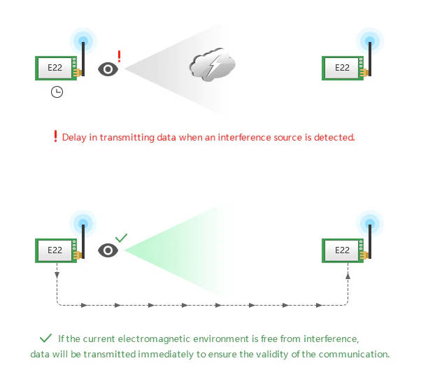
Monitor data before transmission
When enabled, wireless data will be monitored before it is transmitted, avoiding interference to a certain extent, but may cause data delay.
| LBT enable byte | Constant value |
|---|---|
| Enable | LBT_ENABLED |
| Disable (default) | LBT_DISABLED |
WOR cycle
If WOR is transmitting: after the WOR receiver receives the wireless data and outputs it through the serial port, it will wait for 1000ms before entering the WOR again. Users can input the serial port data and return it via wireless during this period. Each serial byte will be refreshed for 1000ms. Users must transmit the first byte within 1000ms.
- Period T = (1 + WOR) * 500ms, maximum 4000ms, minimum 500ms
- The longer the WOR monitoring interval period, the lower the average power consumption, but the greater the data delay
- Both the transmitter and the receiver must be the same (very important).
| Wireless wake-up time | Constant value |
|---|---|
| 500ms | WAKE_UP_500 |
| 1000ms | WAKE_UP_1000 |
| 1500ms | WAKE_UP_1500 |
| 2000ms (default) | WAKE_UP_2000 |
| 2500ms | WAKE_UP_2500 |
| 3000ms | WAKE_UP_3000 |
| 3500ms | WAKE_UP_3500 |
| 4000ms | WAKE_UP_4000 |
Check buffer
First, we must introduce a simple but practical method to check if something is in the receiving buffer.
int available();
It’s simple to return how many bytes you have in the current stream.
Send receive messages
Normal transmission mode
Normal/Transparent transmission mode sends messages to all devices with the same address and channel.
There are a lot of methods to send/receive messages, and we are going to explain in detail:
        ResponseStatus sendMessage(const String message);
        ResponseContainer receiveMessage();
The first method is sendMessage and is used to send a String to a device in Normal mode.
	ResponseStatus rs = e220ttl.sendMessage("Prova");
	Serial.println(rs.getResponseDescription());
The other device simply does on the loop.
       if (e220ttl.available()  > 1){
		ResponseContainer rs = e220ttl.receiveMessage();
		String message = rs.data; // First ever get the data
		Serial.println(rs.status.getResponseDescription());
		Serial.println(message);
	}
Pay attention if you receive multiple messages in the buffer and don’t want to read them all at one time. You must use ResponseContainer rs = e220ttl.receiveMessageUntil(); with a delimiter put on the end of sending a message.
If you enabled the RSSI, you must use receiveMessageRSSI.
Manage structure
If you want to send a complex structure, you can use this method
        ResponseStatus sendMessage(const void *message, const uint8_t size);
        ResponseStructContainer receiveMessage(const uint8_t size);
It’s used to send structure, for example:
	struct Messaggione {
		char type[5];
		char message[8];
		bool mitico;
	};
        struct Messaggione messaggione = {"TEMP", "Peple", true};
        ResponseStatus rs = e220ttl.sendMessage(&messaggione, sizeof(Messaggione));
	Serial.println(rs.getResponseDescription());
and the other side you can receive the message so
		ResponseStructContainer rsc = e220ttl.receiveMessage(sizeof(Messaggione));
		struct Messaggione messaggione = *(Messaggione*) rsc.data;
		Serial.println(messaggione.message);
		Serial.println(messaggione.mitico);
        rsc.close();
If you enabled the RSSI, you must use receiveMessageRSSI.
Read partial structure
If you want to read the first part of the message to manage more types of structure, you can use this method.
ResponseContainer receiveInitialMessage(const uint8_t size);
I create It to receive a string with type or other to identify the structure to load.
		struct Messaggione { // Partial structure without type
			char message[8];
			bool mitico;
		};

		char type[5]; // first part of structure
		ResponseContainer rs = e220ttl.receiveInitialMessage(sizeof(type));
                // Put string in a char array (not needed)
		memcpy ( type, rs.data.c_str(), sizeof(type) );

		Serial.println("READ TYPE: ");
		Serial.println(rs.status.getResponseDescription());
		Serial.println(type);

                // Read the rest of structure
		ResponseStructContainer rsc = e220ttl.receiveMessage(sizeof(Messaggione));
		struct Messaggione messaggione = *(Messaggione*) rsc.data;
        rsc.close();
Fixed mode instead of normal mode
Similarly, I create a set of methods to use with the fixed transmission.
Fixed transmission
You need to change only the sending method because the destination device doesn’t receive the preamble with Address and Channel when setting the fixed mode.
So for the String message, you have
        ResponseStatus sendFixedMessage(byte ADDH, byte ADDL, byte CHAN, const String message);
        ResponseStatus sendBroadcastFixedMessage(byte CHAN, const String message);
and for the structure, you have
        ResponseStatus sendFixedMessage(byte ADDH, byte ADDL, byte CHAN, const void *message, const uint8_t size);
        ResponseStatus sendBroadcastFixedMessage(byte CHAN, const void *message, const uint8_t size );
Here is a simple example
	ResponseStatus rs = e220ttl.sendFixedMessage(0, 0, 0x17, &messaggione, sizeof(Messaggione));
//	ResponseStatus rs = e220ttl.sendFixedMessage(0, 0, 0x17, "Ciao");
Fixed transmission have more scenarios
If you send to a specific device (second scenario Fixed transmission), you must add ADDL, ADDH, and CHAN to identify It directly.
ResponseStatus rs = e220ttl.sendFixedMessage(2, 2, 0x17, "Message to a device");
If you want to send a message to all devices in a specified Channel, you can use this method.
ResponseStatus rs = e220ttl.sendBroadcastFixedMessage(0x17, "Message to a devices of a channel");
If you wish to receive all broadcast messages in the network, you must set your ADDH and ADDL with BROADCAST_ADDRESS.
        ResponseStructContainer c;
	c = e220ttl.getConfiguration();
	// It's important get configuration pointer before all other operation
	Configuration configuration = *(Configuration*) c.data;
	Serial.println(c.status.getResponseDescription());
	Serial.println(c.status.code);

	printParameters(configuration);
	configuration.ADDL = BROADCAST_ADDRESS;
	configuration.ADDH = BROADCAST_ADDRESS;

	// Set configuration changed and set to not hold the configuration
	ResponseStatus rs = e220ttl.setConfiguration(configuration, WRITE_CFG_PWR_DWN_LOSE);
	Serial.println(rs.getResponseDescription());
	Serial.println(rs.code);
	printParameters(configuration);
        c.close();
Thanks
Now you have all information to do your work, but I think It’s important to show some real examples to understand better all the possibilities.
- Ebyte LoRa E220 device for Arduino, esp32 or esp8266: settings and basic usage
- Ebyte LoRa E220 device for Arduino, esp32 or esp8266: library
- Ebyte LoRa E220 device for Arduino, esp32 or esp8266: configuration
- Ebyte LoRa E220 device for Arduino, esp32 or esp8266: fixed transmission, broadcast, monitor, and RSSI
- Ebyte LoRa E220 device for Arduino, esp32 or esp8266: power-saving and sending structured data
- Ebyte LoRa E220 device for Arduino, esp32 or esp8266: WOR microcontroller and Arduino shield
- Ebyte LoRa E220 device for Arduino, esp32 or esp8266: WOR microcontroller and WeMos D1 shield
- Ebyte LoRa E220 device for Arduino, esp32 or esp8266: WOR microcontroller and esp32 dev v1 shield
- Mischianti Arduino LoRa shield (Open source)
- Mischianti WeMos LoRa shield (Open source)
- Mischianti ESP32 DOIT DEV KIT v1 shield (Open source)


Hi Renzo,
I should have read this description first…
Bye Simon
Heheheh… don’t worry.
Bye Renzo
Hi Renzo,
I would want to make a transmitter transmit about 5 variables and a reciever to recieve them I’m using Ebyte E220-900T22D to be exact and I’m pretty new to coding so I don’t really understand the library. Whats steps should I take ?
make configuration and witch examples should I use ?
Thanks in advance.
Ben.
Hi Piksar,
you can follow the steps in this article
Ebyte LoRa E220 device for Arduino, esp32 or esp8266: manage Wake On Radio and sends structured data – 5
Or you can simply send a string message with separators or less efficient but widely used send a json.
Bye Renzo
Hello Renzo! How to use the CRYPT option in your library?
Hi leonid,
It’s the cryptography key, the E220 device send encrypted message to protect possible sniffing.
Remember if you change this key, you must change It on every device that want communicate.
Bye Renzo