
VCC-GND Studio YD-ESP32-S3 (DevKitC 1 clone): high-resolution pinout and specs
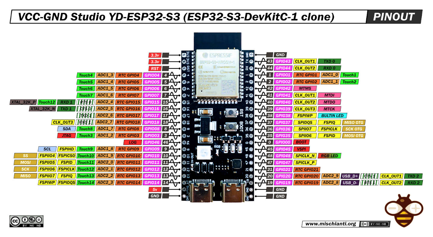
Here a cloned ESP32-S3-DevKitC-1 WiFi Bluetooth-compatible BLE 5.0 Mesh Development Board! This exceptional piece of hardware is designed with all the features of the original ESP32-S3-DevKitC-1, but is upgraded with a USB Type-C connection for added convenience and future compatibility.
Our ESP32-S3-DevKitC-1 clone maintains the WiFi and Bluetooth capabilities of the original, offering seamless connectivity for a wide range of applications. It’s an ideal choice for those interested in IoT projects, as it offers both Bluetooth Low Energy 5.0 and mesh networking capabilities, providing robust wireless communication options that can adapt to various project needs.
The ESP32 Wireless Module at the heart of this development board offers performance with a potent combination of processing power, versatility, and energy efficiency. This makes it perfect for applications from simple connected devices to complex, data-heavy IoT systems.
Here a short selection of esp32s3 ESP32 S3 Purlple AI-S3 - YD-ESP32-S3 - ESP32-S3-DevKitC-1 - ESP32-S3-DevKitC-1 - ESP32-S3 Board screen - ESP32-S3 Zero
Specifications
| Key Component | Description |
|---|---|
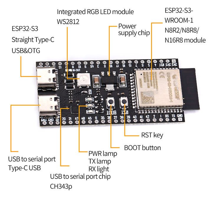
| ESP32-S3-WROOM-1/1U/2 | ESP32-S3-WROOM-1, ESP32-S3-WROOM-1U, and ESP32-S3-WROOM-2 are powerful, generic Wi-Fi + Bluetooth LE MCU modules that have a rich set of peripherals. They provide acceleration for neural network computing and signal processing workloads. ESP32-S3-WROOM-1 and ESP32-S3-WROOM-2 comes with a PCB antenna. ESP32-S3-WROOM-1U comes with an external antenna connector. |
| 5 V to 3.3 V LDO | Power regulator that converts a 5 V supply into a 3.3 V output. |
| Pin Headers | All available GPIO pins (except for the SPI bus for flash) are broken out to the pin headers on the board for easy interfacing and programming. For details, please see Header Block. |
| USB-to-UART Port | A USB Type-C port is used for power supply to the board, for flashing applications to the chip, and for communication with the chip via the on-board USB-to-UART bridge. |
| Boot Button | Download button. Holding down Boot and then pressing Reset initiates Firmware Download mode for downloading firmware through the serial port. |
| Reset Button | Press this button to restart the system. |
| USB Port | ESP32-S3 full-speed USB OTG interface, compliant with the USB 1.1 specification. The interface is used for power supply to the board, for flashing applications to the chip, for communication with the chip using USB 1.1 protocols, as well as for JTAG debugging. |
| USB-to-UART Bridge | Single USB-to-UART bridge chip provides transfer rates up to 3 Mbps. |
| RGB LED | Addressable RGB LED, driven by GPIO48, and you can use LED_BUILTIN (49+48=97) as normal LED. |
| 3.3 V Power On LED | Turns on when the USB power is connected to the board. |
In boards featuring ESP32-S3-WROOM-1/1U modules with Octal SPI flash/PSRAM memory, or ESP32-S3-WROOM-2 modules, the GPIO35, GPIO36, and GPIO37 pins are reserved for internal communication between the ESP32-S3 and the SPI flash/PSRAM memory.
CPU and Memory
- Xtensa® dual-core 32-bit LX7 microprocessor,
up to 240 MHz - CoreMark® score:
– 1 core at 240 MHz: 613.86 CoreMark; 2.56 CoreMark/MHz
– 2 cores at 240 MHz: 1181.60 CoreMark; 4.92 CoreMark/MHz - 128-bit data bus and SIMD commands
- 384 KB ROM
- 512 KB SRAM
- 16 KB SRAM in RTC
- SPI, Dual SPI, Quad SPI, Octal SPI, QPI and OPI interfaces that allow connection to multiple flash and external RAM
- Flash controller with cache is supported
- Flash in-Circuit Programming (ICP) is supported
Advanced Peripheral Interfaces
- 45 × programmable GPIOs
- Digital interfaces:
– 4 × SPI
– 1 × LCD interface (8-bit ~16-bit parallel RGB, I8080 and MOTO6800), supporting conversion between RGB565, YUV422, YUV420 and YUV411
– 1 × DVP 8-bit ~16-bit camera interface
– 3 × UART
– 2 × I2C
– 2 × I2S
– 1 × RMT (TX/RX)
– 1 × pulse counter
– LED PWM controller, up to 8 channels
– 1 × full-speed USB OTG
– 1 × USB Serial/JTAG controller
– 2 × MCPWM
– 1 × SDIO host controller with 2 slots
– General DMA controller (GDMA), with 5 transmit channels and 5 receive channels Espressif Systems 3
Submit Documentation Feedback ESP32-S3 Series Datasheet v1.6
– 1 × TWAI® controller, compatible with ISO 11898-1 (CAN Specification 2.0) - Analog interfaces:
– 2 × 12-bit SAR ADCs, up to 20 channels
– 1 × temperature sensor
– 14 × touch sensing IOs Timers:
– 4 × 54-bit general-purpose timers
– 1 × 52-bit system timer
– 3 × watchdog timers
Every variant has its Flash management.
| Ordering Code | Module Integrated | Flash | PSRAM | SPI Voltage |
|---|---|---|---|---|
| ESP32-S3-DevKitC-1-N8 | ESP32-S3-WROOM-1-N8 | 8 MB QD | — | 3.3 V |
| ESP32-S3-DevKitC-1-N8R2 | ESP32-S3-WROOM-1-N8R2 | 8 MB QD | 2 MB QD | 3.3 V |
| ESP32-S3-DevKitC-1-N8R8 | ESP32-S3-WROOM-1-N8R8 | 8 MB QD | 8 MB OT | 3.3 V |
| ESP32-S3-DevKitC-1-N16R8V | ESP32-S3-WROOM-2-N16R8V | 16 MB OT | 8 MB OT | 1.8 V |
| ESP32-S3-DevKitC-1-N32R8V | ESP32-S3-WROOM-2-N32R8V | 32 MB OT | 8 MB OT | 1.8 V |
| ESP32-S3-DevKitC-1U-N8 | ESP32-S3-WROOM-1U-N8 | 8 MB QD | — | 3.3 V |
| ESP32-S3-DevKitC-1U-N8R2 | ESP32-S3-WROOM-1U-N8R2 | 8 MB QD | 2 MB QD | 3.3 V |
| ESP32-S3-DevKitC-1U-N8R8 | ESP32-S3-WROOM-1U-N8R8 | 8 MB QD | 8 MB OT | 3.3 V |
Wi-Fi
- IEEE 802.11 b/g/n-compliant
- Supports 20 MHz, 40 MHz bandwidth in 2.4 GHz band
- 1T1R mode with data rate up to 150 Mbps
- Wi-Fi Multimedia (WMM)
- TX/RX A-MPDU, TX/RX A-MSDU
- Immediate Block ACK
- Fragmentation and defragmentation
- Automatic Beacon monitoring (hardware TSF)
- 4 × virtual Wi-Fi interfaces
- Simultaneous support for Infrastructure BSS in Station, SoftAP, or Station + SoftAP modes Note that when ESP32-S3 scans in Station mode, the SoftAP channel will change along with the Station channel
- Antenna diversity
- 802.11mc FTM
Bluetooth
- Bluetooth LE: Bluetooth 5, Bluetooth mesh
- High power mode (20 dBm)
- Speed: 125 Kbps, 500 Kbps, 1 Mbps, 2 Mbps
- Advertising extensions
- Multiple advertisement sets
- Channel selection algorithm #2
- Internal co-existence mechanism between Wi-Fi and Bluetooth to share the same antenna
Low Power Management
- Power Management Unit with five power modes
- Ultra-Low-Power (ULP) coprocessors:
– ULP-RISC-V coprocessor
– ULP-FSM coprocessor
Security
- Secure boot
- Flash encryption
- 4-Kbit OTP, up to 1792 bits for users
- Cryptographic hardware acceleration:
– AES-128/256 (FIPS PUB 197)
– Hash (FIPS PUB 180-4)
– RSA
– Random Number Generator (RNG)
– HMAC
– Digital signature
How to
- ESP32: pinout, specs and Arduino IDE configuration
- ESP32: integrated SPIFFS Filesystem
- ESP32: manage multiple Serial and logging
- ESP32 practical power saving
- ESP32 practical power saving: manage WiFi and CPU
- ESP32 practical power saving: modem and light sleep
- ESP32 practical power saving: deep sleep and hibernation
- ESP32 practical power saving: preserve data, timer and touch wake up
- ESP32 practical power saving: external and ULP wake up
- ESP32 practical power saving: UART and GPIO wake up
- ESP32: integrated LittleFS FileSystem
- ESP32: integrated FFat (Fat/exFAT) FileSystem
- ESP32-wroom-32
- ESP32-CAM
- ESP32: use ethernet w5500 with plain (HTTP) and SSL (HTTPS)
- ESP32: use ethernet enc28j60 with plain (HTTP) and SSL (HTTPS)
- How to use SD card with esp32
- esp32 and esp8266: FAT filesystem on external SPI flash memory
- Firmware and OTA update management
- Firmware management
- OTA update with Arduino IDE
- OTA update with Web Browser
- Self OTA uptate from HTTP server
- Non-standard Firmware update
- Integrating LAN8720 with ESP32 for Ethernet Connectivity with plain (HTTP) and SSL (HTTPS)
- Connecting the EByte E70 to ESP32 c3/s3 devices and a simple sketch example
- ESP32-C3: pinout, specs and Arduino IDE configuration
- Integrating W5500 with ESP32 Using Core 3: Native Ethernet Protocol Support with SSL and Other Features
- Integrating LAN8720 with ESP32 Using Core 3: Native Ethernet Protocol Support with SSL and Other Features
- Dallas ds18b20:
- Guide to I2C on ESP32: Communication with Heterogeneous 5V and 3.3V Devices, Additional Interface Management and Scanner
- Display
- Complete Guide: Using an ILI9341 Display with the TFT_eSPI Library
- Integrating Touch Screen Functionality with Your ILI9341 TFT Display
- SSD1683 eInk Display with GxEPD and ESP32 (and CrowPanel 4.2″ HMI): basics and configuration
Datasheet
ESP32s3 datasheet
Board Schematic
PCB size
Thanks
- Arduino
- esp8285
- esp8266
- ESP32
- DOIT ESP32 DEV KIT v1
- ESP32 DevKitC v4
- ESP32 WeMos LOLIN32
- ESP32 WeMos LOLIN32 Lite
- ESP32 WeMos LOLIN D32
- ESP32-wroom-32
- NodeMCU-32S
- ESP32-S
- ESP32-CAM
- ESP32-2432S028 (Cheap Yellow Display)
- ESP32-2432S032 (Cheap Yellow Display)
- ESP32 s2
- ESP32c3
- ESP32s3
- Arduino SAMD
- STM32
- Raspberry Pi


The ‘ESP32 S3 DevKitC1 Clone’ board has a jumper called ‘RGB’ and another called ‘USB-OTG’, both are open. But it may be necessary to solder the jumper for the devices to work.
The ‘ESP32 S3 DevKitC1 Clone’ board has a jumper called ‘IN-OUT’.
“In-Out, when closed, bypasses one diode, making USB VBus power coming to 5Vin. If 5Vin is also connected to external source, it can get back-fed by USB, which is usually undesirable. But USB bus is protected by another diode, it cannot get back-fed by external source.
When In-Out is open, 5Vin and USB VBus are separated by diode, USB power does not come to 5Vin.
USB-OTG jumper, when closed, connects together USB VBus lines from both USB-C connectors.”
Ref.: https://www.reddit.com/r/esp32/comments/10rdngp/thirdparty_esp32s3_development_boards_inout_and/?rdt=39953
Hi R,
thanks for the usefully information.
Bye Renzo
The RGB led did not work with common digitalWrite() commands. LED only worked with neopixelWrite() commands.
“There is a BlinkRGB under the ESP32->GPIO examples that uses the onboard RGB LED.”
Ref.: https://forum.arduino.cc/t/esp32-s3-devkit-problems/1136923/4
Hi,
Since I am new to ESP32 and KiCAD I will be grateful if you can send to me KiCAD or similar project with complete board (I still don’t know how to draw in KiCAD). Thanks’
Hi Tobi,
sorry, I don’t have that.
Bye Renzo