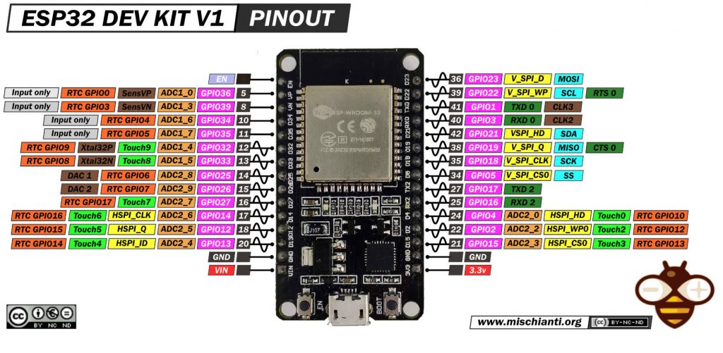
DOIT ESP32 DEV KIT v1: high resolution pinout and specs
Link to the high resolution pinout image
The DoIt ESP32 DevKit V1 is a development board that features the ESP32 microcontroller from Espressif. It is designed for IoT (Internet of Things) projects and applications.
You can find It here ESP32 Dev Kit v1 - TTGO T-Display 1.14 ESP32 - NodeMCU V3 V2 ESP8266 Lolin32 - NodeMCU ESP-32S - WeMos Lolin32 - WeMos Lolin32 mini - ESP32-CAM programmer - ESP32-CAM bundle - ESP32-WROOM-32 - ESP32-S
The board includes Wi-Fi and Bluetooth capabilities, a variety of input/output interfaces including GPIO, analog inputs, UART, SPI, and I2C. It also has a standard form factor that makes it easy to embed in projects and a USB port for power and programming. The ESP32 DevKit V1 is popular among hobbyists and educators for its ease of use and versatility in various electronic projects.
Specifications
- Processors:
- CPU: Xtensa dual-core (or single-core) 32-bit LX6 microprocessor, operating at 160 or 240 MHz and performing at up to 600 DMIPS
- Ultra low power (ULP) co-processor
- Memory: 520 KiB SRAM
- Wireless connectivity:
- Wi-Fi: 802.11 b/g/n
- Bluetooth: v4.2 BR/EDR and BLE (shares the radio with Wi-Fi)
- Peripheral interfaces:
- 12-bit SAR ADC up to 18 channels
- 2 × 8-bit DACs
- 10 × touch sensors (capacitive sensing GPIOs)
- 4 × SPI
- 2 × I²S interfaces
- 2 × I²C interfaces
- 3 × UART
- SD/SDIO/CE-ATA/MMC/eMMC host controller
- SDIO/SPI slave controller
- Ethernet MAC interface with dedicated DMA and IEEE 1588 Precision Time Protocol support
- CAN bus 2.0
- Infrared remote controller (TX/RX, up to 8 channels)
- Motor PWM
- LED PWM (up to 16 channels)
- Hall effect sensor
- Ultra low power analog pre-amplifier
- Security:
- IEEE 802.11 standard security features all supported, including WFA, WPA/WPA2 and WAPI
- Secure boot
- Flash encryption
- 1024-bit OTP, up to 768-bit for customers
- Cryptographic hardware acceleration: AES, SHA-2, RSA, elliptic curve cryptography (ECC), random number generator (RNG)
- Power management:
- Internal low-dropout regulator
- Individual power domain for RTC
- 5μA deep sleep current
- Wake up from GPIO interrupt, timer, ADC measurements, capacitive touch sensor interrupt
Pinout description
The DoIt ESP32 DevKit V1 features a comprehensive pinout that caters to a wide range of functionalities. Here’s a brief overview of its pinout:
- GPIO Pins: The board provides numerous General Purpose Input/Output (GPIO) pins which can be used for various digital input/output functionalities. These pins also support functionalities like PWM, I2C, SPI, and more.
- Analog Inputs: Several pins on the ESP32 DevKit V1 are capable of reading analog signals, making them suitable for interfacing with analog sensors.
- 3.3V and GND Pins: These are used to power external components or sensors.
- 5V and GND: The board can also provide a 5V output, which is useful for powering external modules that require more power.
- VIN: This is the input voltage pin, which can be used to power the board when not using the USB connection.
- EN: This is the enable pin. It’s used to reset the microcontroller.
- TX/RX: These pins are used for serial communication.
- SPI Interface: The board has pins for SPI communication, enabling fast data transfer with peripherals like displays or flash memory.
- I2C Interface: The ESP32 DevKit V1 supports I2C communication, which is widely used for interfacing with sensors and other peripherals.
- Touch Sensor Pins: Some GPIOs can be used as capacitive touch inputs, offering an interface for touch-based input devices.
- VP/VN: These are the pins for the internal hall effect sensor.
- USB-to-UART Bridge: This feature is crucial for programming the ESP32 using a USB cable and also for serial communication with a computer or other USB host devices.
This board’s flexibility with various protocols and interfaces makes it ideal for a wide range of IoT and embedded system applications.
How to
- ESP32: pinout, specs and Arduino IDE configuration
- ESP32: integrated SPIFFS Filesystem
- ESP32: manage multiple Serial and logging
- ESP32 practical power saving
- ESP32 practical power saving: manage WiFi and CPU
- ESP32 practical power saving: modem and light sleep
- ESP32 practical power saving: deep sleep and hibernation
- ESP32 practical power saving: preserve data, timer and touch wake up
- ESP32 practical power saving: external and ULP wake up
- ESP32 practical power saving: UART and GPIO wake up
- ESP32: integrated LittleFS FileSystem
- ESP32: integrated FFat (Fat/exFAT) FileSystem
- ESP32-wroom-32
- ESP32-CAM
- ESP32: use ethernet w5500 with plain (HTTP) and SSL (HTTPS)
- ESP32: use ethernet enc28j60 with plain (HTTP) and SSL (HTTPS)
- How to use SD card with esp32
- esp32 and esp8266: FAT filesystem on external SPI flash memory
- Firmware and OTA update management
- Firmware management
- OTA update with Arduino IDE
- OTA update with Web Browser
- Self OTA uptate from HTTP server
- Non-standard Firmware update
- Integrating LAN8720 with ESP32 for Ethernet Connectivity with plain (HTTP) and SSL (HTTPS)
- Connecting the EByte E70 to ESP32 c3/s3 devices and a simple sketch example
- ESP32-C3: pinout, specs and Arduino IDE configuration
- Integrating W5500 with ESP32 Using Core 3: Native Ethernet Protocol Support with SSL and Other Features
- Integrating LAN8720 with ESP32 Using Core 3: Native Ethernet Protocol Support with SSL and Other Features
- Dallas ds18b20:
- Guide to I2C on ESP32: Communication with Heterogeneous 5V and 3.3V Devices, Additional Interface Management and Scanner
- Display
- Complete Guide: Using an ILI9341 Display with the TFT_eSPI Library
- Integrating Touch Screen Functionality with Your ILI9341 TFT Display
- SSD1683 eInk Display with GxEPD and ESP32 (and CrowPanel 4.2″ HMI): basics and configuration
Datasheet
Schema
ESP32
ESP32-WROOM-32
Wiki
Thanks
- Arduino
- esp8285
- esp8266
- ESP32
- DOIT ESP32 DEV KIT v1
- ESP32 DevKitC v4
- ESP32 WeMos LOLIN32
- ESP32 WeMos LOLIN32 Lite
- ESP32 WeMos LOLIN D32
- ESP32-wroom-32
- NodeMCU-32S
- ESP32-S
- ESP32-CAM
- ESP32-2432S028 (Cheap Yellow Display)
- ESP32-2432S032 (Cheap Yellow Display)
- ESP32 s2
- ESP32c3
- ESP32s3
- Arduino SAMD
- STM32
- Raspberry Pi


Hi there, Is that possible that we can also get the board dimensions of this part? we are trying to create a footprint and we need that information.
Hi Ron,
the size is 28,2mm x 51,800mm, but here you can find the svg file in real size, with all holes and pins.
I think It’s good for you.
Tell me if you need more informations.
Bye Renzo
well i really need the dimensions of this board for footprint, like the gap between pins and so on . I hope you can help me out my man..
Hi Aidil,
the svg in the comment is in realsize, so you can get all the dimension you want.
Bye Renzo
bullshit mine has 36 pins. thats 18 on each side for the FUCK IT DEVIT
Hi, hehehehe check this
ESP32 DevKitC v4 high resolution pinout and specs
Bye Renzo
hello, i need to fine the exact measures of the module of the esp32 devkit v1 (30 pins) like the distance between pin-pin
Hi joaquin,
you can find an image of It in real size.
Bye Renzo
is it possible to add an antenna to the board?
Hi Davey,
you can add It, but It isn’t a simple operation:
but I think It’s better if you chose a micro that use 32U version of esp32 (with embedded antenna connector).
Bye Renzo
sir how many esp32 boards types are avalabile l
Hi,
exist a lot of prototype board, some of the main manufacturer are WeMos, Lilygo, Waveshare.
Bye Renzo
“5V and GND: The board can also provide a 5V output, which is useful for powering external modules that require more power.”
That’s not true. There is not pin to handle 5V output.
Hi M,
The datasheet explains that EXT_5V is used for USB and VIN, so you can use It, and I used it for my project with success.
Bye Renzo
Hello, continuing M’s topic – I am powering the board via the USB so at my Vin I am having 5V. I am using those 5V to power the circuit I am using but is there a possibility to toggle between ON and OFF this Vin output?
Hi The,
no It’s directly connected to the USB. To control the power you can use a transistor like the 2n2222.
Bye Renzo
Hello, how come the devkit-v1 board has 30 pins, the pinout of the board reflects this too, but the schematic presents 2 20 pin connectors with 19 active pins on each side??
Hi,
I think you are right, I’m going to fix.
Bye Renzo