DOIT DT-06: high-resolution pinout and specs
The DT-06 is a TTL-WiFi module developed by Doctors of Intelligence & Technology Co. LTD. It is designed based on the ESP-M2 WiFi module and features transparent transmission capabilities.
Link to the high resolution image
Here my tested device DT-06
Specs
Importantly, the TTL-WiFi is already built-in in the serial transparent transmission firmware programmed, which can realize the transparent transmit the data in real-time, together with low-power control, and status indictor. This board can replace the old wiring serial WiFi device to realize the data collection and control. It has the following features.
- Built-in the high performance WiFi module ESP-M2 with size: 34mm*17mm*4mm;
- Working voltage: 4.5V~6.0V, TTL working voltage: 3.3V (compatible with 5.0V);
- Provided pins: STATE, TXD, RXD,EN;
- Average current: 80mA; when data sent, it is 170mA; but it is 20μA at deep sleep mode;
- Built-in HTTP Web Server, support configure parameters by web page;
- Support set baud rate, data bit, parity check, stop bits, and/or subcontracting time;
- Support baud rate (bps): 300/600/1200/2400/4800/9600/19200/38400/57600/74800/115200/230400/460800/921600/1843200/3686400;
- Provide IO4 to show the WiFi status;
- Working temperature: -40℃-125℃;
ESP-M2 Specs
- SOC features
- Built-in Tensilica L106 ultra-low power consumption 32-bit cpu, the main frequency can be 80MHz and 160MHz, also support RTOS;
- Built-in TCP/IP protocol stack;
- Built-in 1 channel 10-bit high precision ADC;
- Interfaces include HSPI, UART, I2C, I2S, IR Remote Control, PWM, GPIO;
- 20uA deep-sleep current, less than 5uA cut- off current;
- 2ms wake-up time;
- 1.0mW consume power (DTIM3 and standby state);
- Built-in 1M SPI flash byte;
- Wi-Fi features
- Support 802.11 b/g/n/e/i
- Support three modes: Station, SoftAP, and SoftAP+STA;
- Support Wi-Fi Direct(P2P);
- Support hardware acceleration for CCMP (CBC-MAC, computation mode), TKIP (MIC, RC4), WAPI(SMS4), WEP(RC4), CRC;
- P2P detection, P2P GO mode/GC mode and P2P power management;
- WPA/PA2 PSK and WPS;
- Support 802.11 i security: pre-certification and TSN;
- Support 802.11n (2.4 GHz);
- 802.1h/RFC1042 frame encapsulation;
- Support seamless roam;
- Support AT remote upgrade and cloud OTA upgrade;
- Support SmartConfig function for Android and iOS device.
- Module Interface
- 2*UART
- 1*En
- 1*ADC
- 1*wakeup pin;
- 1*HSPI;
- 1*I2C;
- 1*I2S;
- MAX 10* GPIOs;
- Working temperature: -40℃-105℃
Key Features:
- Compatibility: The DT-06 module is fully compatible with the original electrical and physical interfaces for serial transparent Bluetooth HT-06.
- Transparent Transmission: It comes with built-in industrial transparent transmission firmware (V3.0) that supports real-time data transmission between serial and WiFi. This makes it suitable for applications like data collection and control.
- WiFi Module: The module is equipped with a high-performance WiFi module (ESP-M2) with a compact size of 34mm x 17mm x 4mm.
- Voltage Compatibility: It operates at a working voltage of 4.5V to 6.0V, with TTL working voltage at 3.3V (compatible with 5.0V).
- Interfaces: The module provides pins for STATE, TXD, RXD, and EN.
- Low Power: It has an average current consumption of 80mA. During data transmission, it consumes 170mA, and in deep sleep mode, it draws as little as 20μA.
- AT Command Support: The module supports serial AT commands for configuration and control.
- Firmware Update: It supports re-programmable firmware updates over-the-air (OTA).
- Web Configuration: The module features a built-in HTTP web server, allowing users to configure parameters via a web page.
- Network Modes: It supports various network modes, including TCP Server, TCP Client, UDP Server, UDP Client, and UDP local broadcast.
- Built-in HTTP Server: You can configure parameters through a web page, making it user-friendly for setup.
- Temperature Range: It can operate in a wide temperature range from -40°C to 125°C.
Applications: The DT-06 module finds applications in various fields, including smart homes, wireless data connections, transparent data transmission, smart car control, wireless serial printers, LED light industrial control, and more.
The user manual provides detailed information on configuring and using the module, making it a valuable resource for developers and engineers working with TTL-WiFi communication.
Please note that the provided information is based on the user manual you shared, and there may have been updates or changes to the module since the manual’s publication in March 2017. It’s essential to refer to the latest documentation or contact the manufacturer for the most up-to-date information and support.
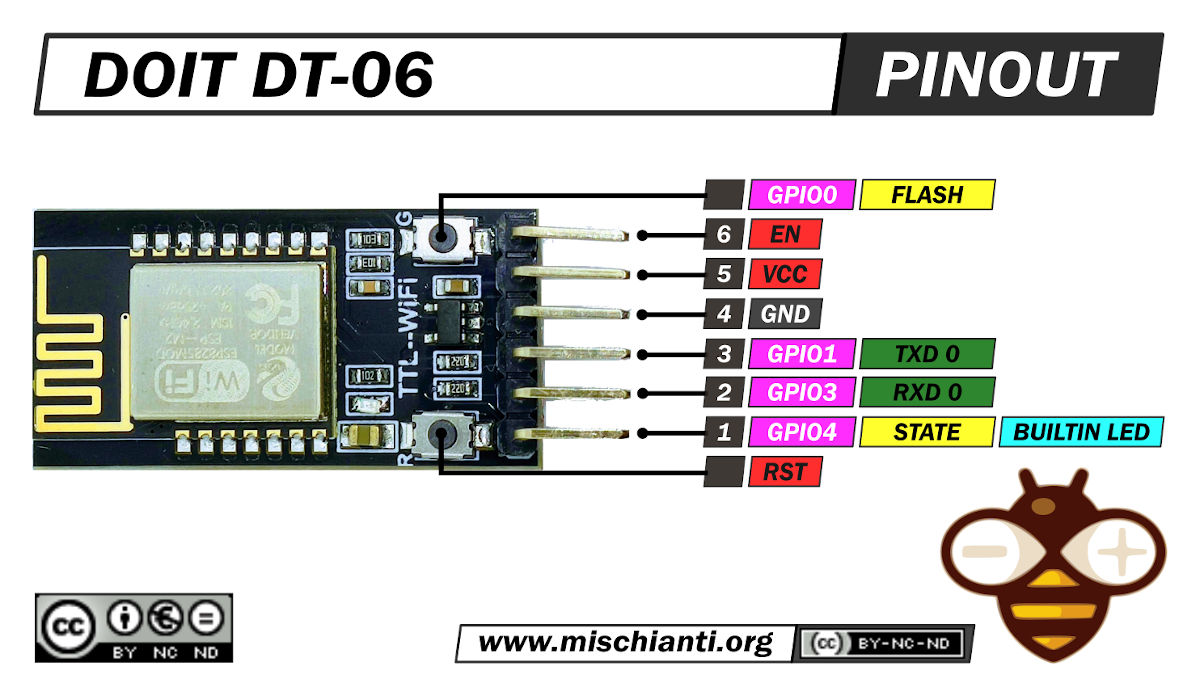
Pinout description
Pinout for the DT-06 TTL-WiFi module:
Pin 1: STATE (I/O – GPIO4)
- This pin serves as the status indicator. It is used to display the network connection status. When the module is connected to a wireless router in STA mode, STATE is at a low level (typically low voltage).
Pin 2: RXD (I/O – GPIO3)
- This pin is for receiving data. It can be connected to the UART Rx (receive) pin of an external microcontroller or device.
Pin 3: TXD (I/O – GPIO1)
- This pin is for transmitting data. It can be connected to the UART Tx (transmit) pin of an external microcontroller or device.
Pin 4: GND (Power)
- This is the ground connection for the module, providing the reference voltage.
Pin 5: VCC (Power)
- This is the power supply pin for the module. It operates within a voltage range of 4.5V to 6.0V, with the recommended voltage being 5.0V.
Pin 6: EN (I – Enable)
- This pin controls the enable/disable state of the module. A high level (logical 1) enables the module to operate normally, while a low level (logical 0) shuts down the module.
Please note that the pins are labeled according to their functions and their corresponding GPIO (General-Purpose Input/Output) numbers. You can connect these pins to other devices or microcontrollers as needed to establish communication and control with the DT-06 module.
Buttons and LED
- SW1 (Button 1):
- Function: This button is used for firmware updates and configuration.
- Connection: It is connected to GPIO0.
- Usage: To download firmware updates, you would typically press SW1 first and then press SW2, followed by releasing both buttons. The exact procedure may vary based on the specific firmware update process.
- SW2 (Button 2):
- Function: This button is also used for firmware updates and configuration.
- Connection: It is connected to the RST (reset) pin.
- Usage: Like SW1, SW2 is involved in firmware update processes. You would press SW2 after pressing SW1 as part of the firmware update procedure.
- LED: is connected to GPIO4 (General Purpose Input/Output Pin 4). The GPIO4 pin is used to control and indicate the status of the LED on the module.
Original firmware LED Indicators
The DT-06 module has several LED indicators, each with its own function:
- LED Indicator 1 (Always On):
- Function: This LED is typically always on.
- Indication: It indicates a successful connection to the wireless router when the module is in STA (Station) mode or STA+AP mode.
- LED Indicator 2 (Slow Blinking):
- Function: This LED blinks slowly at regular intervals.
- Indication:
- In AP (Access Point) mode, it indicates that the module has unsuccessfully connected to the wireless router.
- In STA mode, it indicates that the module is attempting to connect to a wireless router.
- In AP+STA mode, it indicates that the module is trying to connect to the wireless router.
- LED Indicator 3 (Fast Blinking):
- Function: This LED blinks rapidly.
- Indication: When SW1 or the Flash button is pressed and the module receives data via the serial interface or over the network, this LED will blink rapidly.
- LED Indicator 4 (Off):
- Function: This LED remains off.
- Indication: This LED will be off if the WiFi module isn’t functioning due to abnormal power conditions or if it doesn’t have the transparent transmission firmware installed.
Please note that the specific meanings of LED indicators may vary slightly based on the firmware and configuration of the module.
Firmware
Last original firmware from DOIT (with all bug fixes)
Original DOIT firmware with all patch
ESP-LINK firmware with advanced features
How To
- WiFi remote debugging on Arduino with DT-06
- Program Arduino UNO Remotely via WiFi with DT-06 ESP-Link Firmware
Datasheet
DOIT DT-06 documentation
ESP-M2 datasheet
Thanks
- Arduino
- esp8285
- esp8266
- ESP32
- DOIT ESP32 DEV KIT v1
- ESP32 DevKitC v4
- ESP32 WeMos LOLIN32
- ESP32 WeMos LOLIN32 Lite
- ESP32 WeMos LOLIN D32
- ESP32-wroom-32
- NodeMCU-32S
- ESP32-S
- ESP32-CAM
- ESP32-2432S028 (Cheap Yellow Display)
- ESP32-2432S032 (Cheap Yellow Display)
- ESP32 s2
- ESP32c3
- ESP32s3
- Arduino SAMD
- STM32
- Raspberry Pi