
Raspberry Pi Pico W: high-resolution pinout and specs
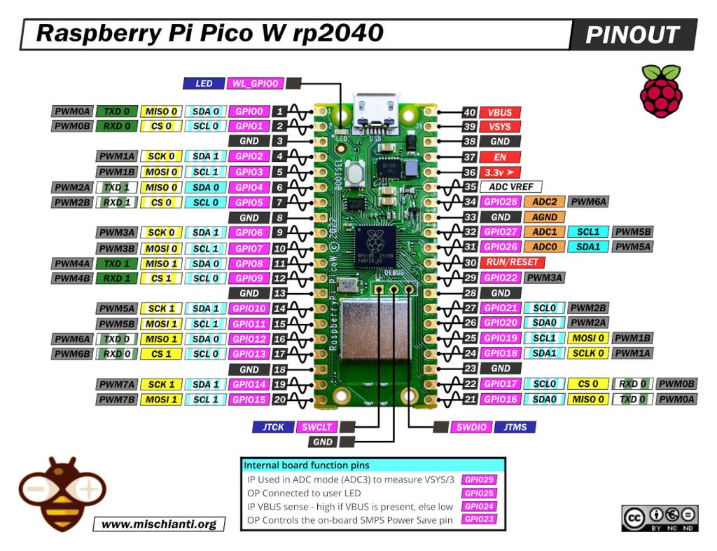
Raspberry Pi Pico W high resolution pinout image
PINs
Power Pins
- VBUS – micro-USB input voltage
- VSYS – main system input voltage
- 3V3 – regulated 3.3V output, 300mA max
- GND – main ground reference
- AGND – ground reference for GP26-29 and ADC0 and ADC1
GPIO Pins
- GP0 to GP28 – General Purpose Input Output (GPIO) as well as Pulse Width Modulation (PWM)
I2C Pins
- SCL0 – I2C port 0 clock
- SDA0 – I2C port 0 data
- SCL1 – I2C port 1 clock
- SDA1 – IC2 port 1 data
SPI Pins
- SCLK0 – SPI port 0 clock
- MOSI0 – SPI port 0 data out
- MISO0 – SPI port 0 data in
- SCLK1 – SPI port 1 clock
- MOSI1 – SPI port 1 data out
- MISO1 – SPI port 1 data in
ADC Pins
- ADC0 – Analog to Digital Converter (ADC) 0
- ADC1 – Analog to Digital Converter (ADC) 1
- ADC2 – Analog to Digital Converter (ADC) 2
Specs
Raspberry Pi Pico W has been designed to be a low-cost yet flexible development platform for RP2040, with a 2.4GHz wireless interface and the following key features:
rp2040
- Dual-core cortex M0+ at up to 133MHz
- On-chip PLL allows variable core frequency
- 264kB multi-bank high-performance SRAM
- External Quad-SPI Flash with eXecute In Place (XIP) and 16kB on-chip cache
- High-performance full-crossbar bus fabric
- On-board USB1.1 (device or host)
- 30 multi-function General Purpose IO (4 can be used for ADC)
- 1.8-3.3V IO Voltage (NOTE Pico IO voltage is fixed at 3.3V)
- 12-bit 500ksps Analogue to Digital Converter (ADC)
- Various digital peripherals
- 2 × UART, 2 × I2C, 2 × SPI, 16 × PWM channels
- 1 × Timer with 4 alarms, 1 × Real Time Counter
- 2 × Programmable IO (PIO) blocks, 8 state machines total
- Flexible, user-programmable high-speed IO
- Can emulate interfaces such as SD Card and VGA
- RP2040 microcontroller with 2MB Flash
- Micro-USB B port for power and data (and for reprogramming the Flash)
- 40 pin 21×51 ‘DIP’ style 1mm thick PCB with 0.1″ through-hole pins also with edge castellations
- Exposes 26 multi-function 3.3V General Purpose I/O (GPIO)
- 23 GPIO are digital-only, and three are ADC capable
- It can be surface mounted as a module
- 3-pin ARM Serial Wire Debug (SWD) port
- Simple yet highly flexible power supply architecture
- Various options for easily powering the unit from micro-USB, external supplies, or batteries
Infineon’s AIROC CYW43439
WiFi
- Wi-Fi 4 (802.11n), Single-band (2.4 GHz)
- 1×1 SISO
- 20 MHz channels, up to 96 Mbps PHY data rate
- Integrated internal PA, LNA, and T/R switch supports a single antenna shared between Wi-Fi and Bluetooth
Bluetooth (Not active now)
- Class 1 (100 m) and Class 2 (10 m) operation
- Bluetooth® 5.2
- Supports BDR (1Mbps), EDR (2/3Mbps), and Bluetooth® LE
Pico W has an onboard 2.4GHz wireless interface using an Infineon CYW43439. The antenna is an onboard antenna licensed from ABRACON (formerly ProAnt). The wireless interface is connected via SPI to the RP2040.
Pico SDK includes wireless networking support. The network stack is built around lwIP, and uses libcyw43 from Damien George (of MicroPython fame) to communicate with the wireless chip. By default, libcyw43 is licensed for non-commercial use, but Pico W users, and anyone else who builds their product around RP2040 and CYW43439, benefit from a free commercial-use license.
How to
- Raspberry Pi Pico and rp2040 boards: pinout, specs, and Arduino IDE configuration
- Raspberry Pi Pico and rp2040 boards: integrated LittleFS filesystem
- Raspberry Pi Pico and rp2040 board: ethernet w5500 with plain (HTTP) and SSL (HTTPS) requests
- Raspberry Pi Pico and rp2040 boards: WiFiNINA with ESP32 WiFi Co-Processor
- Raspberry Pi Pico and rp2040 boards: how to use SD card
- Dallas ds18b20
- Connecting the EByte E70 to Raspberry Pi Pico (rp2040) devices and a simple sketch example
Datasheet and schema
Pico W
Infineon’s AIROC CYW43439
Thanks
- Arduino
- esp8285
- esp8266
- ESP32
- DOIT ESP32 DEV KIT v1
- ESP32 DevKitC v4
- ESP32 WeMos LOLIN32
- ESP32 WeMos LOLIN32 Lite
- ESP32 WeMos LOLIN D32
- ESP32-wroom-32
- NodeMCU-32S
- ESP32-S
- ESP32-CAM
- ESP32-2432S028 (Cheap Yellow Display)
- ESP32-2432S032 (Cheap Yellow Display)
- ESP32 s2
- ESP32c3
- ESP32s3
- Arduino SAMD
- STM32
- Raspberry Pi


The pinout image has one error.
The LED is not connected to GPIO25, it connected to WL_GPIO0
Ops.. yes It’s true, I get It from the Pico datasheet, not Pico W.
Thanks for the reporting Renzo
I think even
1. OP Controls on board SMPS Power Save Pin————-> WL_GPIO1
2. IPVBus Sense-High if VBUS is present,else-Low——–> WL_GPIO2