
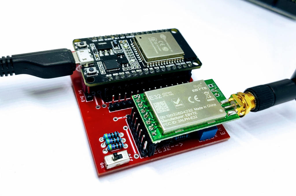
Ebyte LoRa E32 device for Arduino, esp32 or esp8266: WOR (wake on radio) and new ESP32 shield – 8
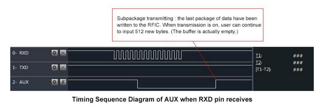
We have seen how this device (E32 UART LoRa based on popular SX1276/SX1278 Wireless Modules ) manages power saving, but If we use power saving only for the e32 the microcontroller continue to rest active, but we can use AUX pin to resolve this problem.
You can find module here AliExpress (433MHz 5Km) - AliExpress (433MHz 8Km) - AliExpress (433MHz 16Km) - AliExpress (868MHz 915MHz 5.5Km) - AliExpress (868MHz 915MHz 8Km)
If you have trouble like freeze device, you must put a pull-up 4.7k resistor or better connect to the device AUX pin.
We are going to do this connections to support wake on radio, we use Serial2 for communication, 21 for M0 and 19 for M1, and GPIO15, an RTC pin, for AUX so we can wake our device without problem.
I advise you to read the tutorial on energy saving with ESP32 “ESP32 practical power saving“.
So the new connection schema become like so:
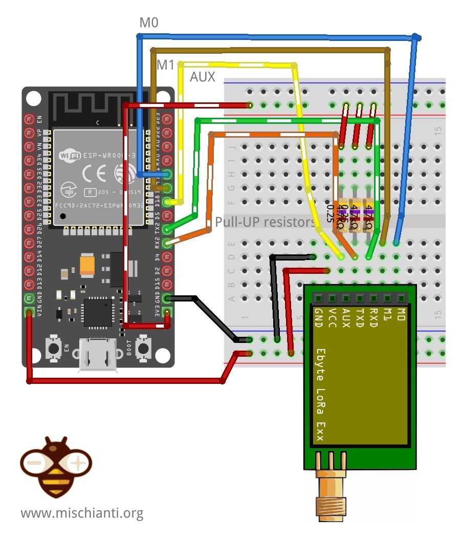
When you are in Sleep mode the e32 put on the buffer the data recived and go immediately LOW, when data is ready return HIGHT, LOW It’s perfect to wake the microcontroller.
ESP32 wake up
As the e32 device, the esp32 have some sleep type, but for this test we are going to use Light sleep with GPIO wake up.
Refer to “ESP32 practical power saving” for a detailed description on sleep mode.
How to put in light sleep ESP32
The command to put on power down the microcontroller is this
    //Go to sleep now
    Serial.println("Going to sleep now");
    delay(100);
    esp_light_sleep_start();
    delay(1000);
But we must specify that the device must wake when AUX pin go LOW
    //wifi_station_disconnect(); //not needed
    esp_sleep_enable_ext0_wakeup(GPIO_NUM_15,LOW);

    //Go to sleep now
    Serial.println("Going to sleep now");
    delay(100);
    esp_light_sleep_start();
    delay(1000);
So the code to receive the alarm from a data transmission becomes like this:
/*
 * LoRa E32-TTL-100
 * Receive fixed transmission message on channel and wake up.
 * https://mischianti.org/
 *
 * E32		  ----- esp32
 * M0         ----- 19 (or GND)
 * M1         ----- 21 (or 3.3v)
 * RX         ----- TX2 (PullUP)
 * TX         ----- RX2 (PullUP)
 * AUX        ----- 15  (PullUP)
 * VCC        ----- 3.3v/5v
 * GND        ----- GND
 *
 */
#include "Arduino.h"
#include "LoRa_E32.h"
#include <WiFi.h>

#define FPM_SLEEP_MAX_TIME           0xFFFFFFF
void callback() {
  Serial.println("Callback");
  Serial.flush();
}

// ---------- esp8266 pins --------------
//LoRa_E32 e32ttl(RX, TX, AUX, M0, M1);  // Arduino RX <-- e22 TX, Arduino TX --> e22 RX
//LoRa_E32 e32ttl(D3, D4, D5, D7, D6); // Arduino RX <-- e22 TX, Arduino TX --> e22 RX AUX M0 M1
//LoRa_E32 e32ttl(D2, D3); // Config without connect AUX and M0 M1

//#include <SoftwareSerial.h>
//SoftwareSerial mySerial(D2, D3); // Arduino RX <-- e22 TX, Arduino TX --> e22 RX
//LoRa_E32 e32ttl(&mySerial, D5, D7, D6); // AUX M0 M1
// -------------------------------------

// ---------- Arduino pins --------------
//LoRa_E32 e32ttl(4, 5, 3, 7, 6); // Arduino RX <-- e22 TX, Arduino TX --> e22 RX AUX M0 M1
//LoRa_E32 e32ttl(4, 5); // Config without connect AUX and M0 M1

//#include <SoftwareSerial.h>
//SoftwareSerial mySerial(4, 5); // Arduino RX <-- e22 TX, Arduino TX --> e22 RX
//LoRa_E32 e32ttl(&mySerial, 3, 7, 6); // AUX M0 M1
// -------------------------------------

// ---------- esp32 pins --------------
LoRa_E32 e32ttl(&Serial2, 15, 21, 19); //  RX AUX M0 M1

//LoRa_E32 e32ttl(&Serial2, 22, 4, 18, 21, 19, UART_BPS_RATE_9600); //  esp32 RX <-- e22 TX, esp32 TX --> e22 RX AUX M0 M1
// -------------------------------------
void printParameters(struct Configuration configuration);
//The setup function is called once at startup of the sketch
void setup()
{
    Serial.begin(9600);
    while (!Serial) {
        ; // wait for serial port to connect. Needed for native USB
    }
    delay(100);

    e32ttl.begin();
        e32ttl.setMode(MODE_2_POWER_SAVING);

//  e32ttl.resetModule();
    // After set configuration comment set M0 and M1 to low
    // and reboot if you directly set HIGH M0 and M1 to program
    ResponseStructContainer c;
    c = e32ttl.getConfiguration();
    Configuration configuration = *(Configuration*) c.data;
    printParameters(configuration);

    configuration.ADDL = 3;
    configuration.ADDH = 0;
    configuration.CHAN = 0x04;
    configuration.OPTION.fixedTransmission = FT_FIXED_TRANSMISSION;
    configuration.OPTION.wirelessWakeupTime = WAKE_UP_250;

    configuration.OPTION.fec = FEC_1_ON;
    configuration.OPTION.ioDriveMode = IO_D_MODE_PUSH_PULLS_PULL_UPS;
    configuration.OPTION.transmissionPower = POWER_20;

    configuration.SPED.airDataRate = AIR_DATA_RATE_010_24;
    configuration.SPED.uartBaudRate = UART_BPS_9600;
    configuration.SPED.uartParity = MODE_00_8N1;

    e32ttl.setConfiguration(configuration, WRITE_CFG_PWR_DWN_SAVE);
    printParameters(configuration);
    // ---------------------------
    delay(1000);
    Serial.println();
    Serial.println("Start sleep!");

	esp_sleep_enable_ext0_wakeup(GPIO_NUM_15,LOW);

	//Go to sleep now
	Serial.println("Going to sleep now");
	delay(100);

	esp_light_sleep_start();

    delay(1000);

    Serial.println();
    Serial.println("Start listening!");

}

// The loop function is called in an endless loop
void loop()
{
    if (e32ttl.available()  > 1){
        ResponseContainer rs = e32ttl.receiveMessage();
        // First of all get the data
        String message = rs.data;

        Serial.println(rs.status.getResponseDescription());
        Serial.println(message);
    }
}

void printParameters(struct Configuration configuration) {
    Serial.println("----------------------------------------");

    Serial.print(F("HEAD : "));  Serial.print(configuration.HEAD, BIN);Serial.print(" ");Serial.print(configuration.HEAD, DEC);Serial.print(" ");Serial.println(configuration.HEAD, HEX);
    Serial.println(F(" "));
    Serial.print(F("AddH : "));  Serial.println(configuration.ADDH, DEC);
    Serial.print(F("AddL : "));  Serial.println(configuration.ADDL, DEC);
    Serial.print(F("Chan : "));  Serial.print(configuration.CHAN, DEC); Serial.print(" -> "); Serial.println(configuration.getChannelDescription());
    Serial.println(F(" "));
    Serial.print(F("SpeedParityBit     : "));  Serial.print(configuration.SPED.uartParity, BIN);Serial.print(" -> "); Serial.println(configuration.SPED.getUARTParityDescription());
    Serial.print(F("SpeedUARTDatte  : "));  Serial.print(configuration.SPED.uartBaudRate, BIN);Serial.print(" -> "); Serial.println(configuration.SPED.getUARTBaudRate());
    Serial.print(F("SpeedAirDataRate   : "));  Serial.print(configuration.SPED.airDataRate, BIN);Serial.print(" -> "); Serial.println(configuration.SPED.getAirDataRate());

    Serial.print(F("OptionTrans        : "));  Serial.print(configuration.OPTION.fixedTransmission, BIN);Serial.print(" -> "); Serial.println(configuration.OPTION.getFixedTransmissionDescription());
    Serial.print(F("OptionPullup       : "));  Serial.print(configuration.OPTION.ioDriveMode, BIN);Serial.print(" -> "); Serial.println(configuration.OPTION.getIODroveModeDescription());
    Serial.print(F("OptionWakeup       : "));  Serial.print(configuration.OPTION.wirelessWakeupTime, BIN);Serial.print(" -> "); Serial.println(configuration.OPTION.getWirelessWakeUPTimeDescription());
    Serial.print(F("OptionFEC          : "));  Serial.print(configuration.OPTION.fec, BIN);Serial.print(" -> "); Serial.println(configuration.OPTION.getFECDescription());
    Serial.print(F("OptionPower        : "));  Serial.print(configuration.OPTION.transmissionPower, BIN);Serial.print(" -> "); Serial.println(configuration.OPTION.getTransmissionPowerDescription());

    Serial.println("----------------------------------------");

}
The result is that the Serial stop on line 98, when we receive the message the e32 wake itself and put AUX LOW, so esp32 wake with interrupt on AUX pin.
Here the sending sketch:
/*
 * LoRa E32-TTL-100
 * Send fixed transmission message to a specified point.
 *
 *
 * E32		  ----- esp32
 * M0         ----- 19 (or 3.3v)
 * M1         ----- 21 (or GND)
 * RX         ----- TX2 (PullUP)
 * TX         ----- RX2 (PullUP)
 * AUX        ----- 15  (PullUP)
 * VCC        ----- 3.3v/5v
 * GND        ----- GND
 *
 */
#include "Arduino.h"
#include "LoRa_E32.h"

// ---------- esp8266 pins --------------
//LoRa_E32 e32ttl(RX, TX, AUX, M0, M1);  // Arduino RX <-- e22 TX, Arduino TX --> e22 RX
//LoRa_E32 e32ttl(D3, D4, D5, D7, D6); // Arduino RX <-- e22 TX, Arduino TX --> e22 RX AUX M0 M1
//LoRa_E32 e32ttl(D2, D3); // Config without connect AUX and M0 M1

//#include <SoftwareSerial.h>
//SoftwareSerial mySerial(D2, D3); // Arduino RX <-- e22 TX, Arduino TX --> e22 RX
//LoRa_E32 e32ttl(&mySerial, D5, D7, D6); // AUX M0 M1
// -------------------------------------

// ---------- Arduino pins --------------
//LoRa_E32 e32ttl(4, 5, 3, 7, 6); // Arduino RX <-- e22 TX, Arduino TX --> e22 RX AUX M0 M1
//LoRa_E32 e32ttl(4, 5); // Config without connect AUX and M0 M1

//#include <SoftwareSerial.h>
//SoftwareSerial mySerial(4, 5); // Arduino RX <-- e22 TX, Arduino TX --> e22 RX
//LoRa_E32 e32ttl(&mySerial, 3, 7, 6); // AUX M0 M1
// -------------------------------------

// ---------- esp32 pins --------------
LoRa_E32 e32ttl(&Serial2, 15, 21, 19); //  RX AUX M0 M1

//LoRa_E32 e32ttl(&Serial2, 22, 4, 18, 21, 19, UART_BPS_RATE_9600); //  esp32 RX <-- e22 TX, esp32 TX --> e22 RX AUX M0 M1
// -------------------------------------

void printParameters(struct Configuration configuration);
void printModuleInformation(struct ModuleInformation moduleInformation);
//The setup function is called once at startup of the sketch
void setup()
{
	Serial.begin(9600);
	while (!Serial) {
	    ; // wait for serial port to connect. Needed for native USB
    }
	delay(100);

	e32ttl.begin();
        e32ttl.setMode(MODE_1_WAKE_UP);

	// After set configuration comment set M0 and M1 to low
	// and reboot if you directly set HIGH M0 and M1 to program
	ResponseStructContainer c;
	c = e32ttl.getConfiguration();
	Configuration configuration = *(Configuration*) c.data;
	configuration.ADDL = 0x01;
	configuration.ADDH = 0x00;
	configuration.CHAN = 0x04;
	configuration.OPTION.fixedTransmission = FT_FIXED_TRANSMISSION;
	configuration.OPTION.wirelessWakeupTime = WAKE_UP_2000;
	e32ttl.setConfiguration(configuration, WRITE_CFG_PWR_DWN_SAVE);
	printParameters(configuration);
	c.close();
	// ---------------------------
}

// The loop function is called in an endless loop
void loop()
{
	delay(2000);

	Serial.println("Send message to 00 03 04");
	ResponseStatus rs = e32ttl.sendFixedMessage(0, 3, 0x04, "Message to 00 03 04 device");
	Serial.println(rs.getResponseDescription());
}

void printParameters(struct Configuration configuration) {
	Serial.println("----------------------------------------");

	Serial.print(F("HEAD : "));  Serial.print(configuration.HEAD, BIN);Serial.print(" ");Serial.print(configuration.HEAD, DEC);Serial.print(" ");Serial.println(configuration.HEAD, HEX);
	Serial.println(F(" "));
	Serial.print(F("AddH : "));  Serial.println(configuration.ADDH, BIN);
	Serial.print(F("AddL : "));  Serial.println(configuration.ADDL, BIN);
	Serial.print(F("Chan : "));  Serial.print(configuration.CHAN, DEC); Serial.print(" -> "); Serial.println(configuration.getChannelDescription());
	Serial.println(F(" "));
	Serial.print(F("SpeedParityBit     : "));  Serial.print(configuration.SPED.uartParity, BIN);Serial.print(" -> "); Serial.println(configuration.SPED.getUARTParityDescription());
	Serial.print(F("SpeedUARTDatte  : "));  Serial.print(configuration.SPED.uartBaudRate, BIN);Serial.print(" -> "); Serial.println(configuration.SPED.getUARTBaudRate());
	Serial.print(F("SpeedAirDataRate   : "));  Serial.print(configuration.SPED.airDataRate, BIN);Serial.print(" -> "); Serial.println(configuration.SPED.getAirDataRate());

	Serial.print(F("OptionTrans        : "));  Serial.print(configuration.OPTION.fixedTransmission, BIN);Serial.print(" -> "); Serial.println(configuration.OPTION.getFixedTransmissionDescription());
	Serial.print(F("OptionPullup       : "));  Serial.print(configuration.OPTION.ioDriveMode, BIN);Serial.print(" -> "); Serial.println(configuration.OPTION.getIODroveModeDescription());
	Serial.print(F("OptionWakeup       : "));  Serial.print(configuration.OPTION.wirelessWakeupTime, BIN);Serial.print(" -> "); Serial.println(configuration.OPTION.getWirelessWakeUPTimeDescription());
	Serial.print(F("OptionFEC          : "));  Serial.print(configuration.OPTION.fec, BIN);Serial.print(" -> "); Serial.println(configuration.OPTION.getFECDescription());
	Serial.print(F("OptionPower        : "));  Serial.print(configuration.OPTION.transmissionPower, BIN);Serial.print(" -> "); Serial.println(configuration.OPTION.getTransmissionPowerDescription());

	Serial.println("----------------------------------------");

}
void printModuleInformation(struct ModuleInformation moduleInformation) {
	Serial.println("----------------------------------------");
	Serial.print(F("HEAD BIN: "));  Serial.print(moduleInformation.HEAD, BIN);Serial.print(" ");Serial.print(moduleInformation.HEAD, DEC);Serial.print(" ");Serial.println(moduleInformation.HEAD, HEX);

	Serial.print(F("Freq.: "));  Serial.println(moduleInformation.frequency, HEX);
	Serial.print(F("Version  : "));  Serial.println(moduleInformation.version, HEX);
	Serial.print(F("Features : "));  Serial.println(moduleInformation.features, HEX);
	Serial.println("----------------------------------------");

}
How to put in deep sleep
To manage deep sleep is more difficult, because you must consider that the AUX pin must be an RTC pin (like GPIO15) when you put in sleep you must hold down the pin to preserve the WOR mode.
When the device is waked from deep sleep reboot, so you lost the message you receive, and you must send another message if you want that receiver read the message.
So the core code that manage deep sleep and wake is
    esp_sleep_wakeup_cause_t wakeup_reason;

    wakeup_reason = esp_sleep_get_wakeup_cause();

    if (ESP_SLEEP_WAKEUP_EXT0 == wakeup_reason) {
    	Serial.println("Waked up from external GPIO!");

    	gpio_hold_dis(GPIO_NUM_21);
    	gpio_hold_dis(GPIO_NUM_19);

    	gpio_deep_sleep_hold_dis();

        e32ttl.setMode(MODE_0_NORMAL);

    	delay(1000);

        e32ttl.sendFixedMessage(0, DESTINATION_ADDL, 23, "We have waked up from message, but we can't read It!");
    }else{
		e32ttl.setMode(MODE_2_POWER_SAVING);

		delay(1000);
		Serial.println();
		Serial.println("Start sleep!");
		delay(100);

		if (ESP_OK == gpio_hold_en(GPIO_NUM_21)){
			Serial.println("HOLD 21");
		}else{
			Serial.println("NO HOLD 21");
		}
		if (ESP_OK == gpio_hold_en(GPIO_NUM_19)){
				Serial.println("HOLD 19");
			}else{
				Serial.println("NO HOLD 19");
			}

		esp_sleep_enable_ext0_wakeup(GPIO_NUM_15,LOW);

		gpio_deep_sleep_hold_en();
		//Go to sleep now
		Serial.println("Going to sleep now");
		esp_deep_sleep_start();

		delay(1);
    }
//	e32ttl.setMode(MODE_0_NORMAL);
//	delay(1000);
    Serial.println();
    Serial.println("Wake and start listening!");
You can see that I use gpio_hold_en to se the pin to preserve state and gpio_deep_sleep_hold_en to activate preservation (Read “ESP32 practical power saving: preserve gpio status, external and ULP wake up” to go in deep), and gpio_hold_dis with gpio_deep_sleep_hold_dis to deactivate.
Then I use wakeup_reason = esp_sleep_get_wakeup_cause(); to check why the device exited from deep sleep, the command esp_sleep_enable_ext0_wakeup(GPIO_NUM_15,LOW); to put AUX pin in listening and finally esp_deep_sleep_start(); to activate deep sleep.
/*
 * EBYTE LoRa E32
 * Stay in sleep mode and wait a wake up WOR message
 *
 * You must configure the address with 0 3 23 with WOR receiver enable
 * and pay attention that WOR period must be the same of sender
 *
 *
 * https://mischianti.org
 *
 * E32		  ----- esp32
 * M0         ----- 19 (or 3.3v)
 * M1         ----- 21 (or GND)
 * RX         ----- TX2 (PullUP)
 * TX         ----- RX2 (PullUP)
 * AUX        ----- 15  (PullUP)
 * VCC        ----- 3.3v/5v
 * GND        ----- GND
 *
 */

// with this DESTINATION_ADDL 2 you must set
// WOR SENDER configuration to the other device and
// WOR RECEIVER to this device
#define DESTINATION_ADDL 2

// If you want use RSSI uncomment //#define ENABLE_RSSI true
// and use relative configuration with RSSI enabled
//#define ENABLE_RSSI true

#include "Arduino.h"
#include "LoRa_E32.h"
#include <WiFi.h>

#include "soc/rtc_cntl_reg.h"
#include "soc/rtc.h"
#include "driver/rtc_io.h"

#define FPM_SLEEP_MAX_TIME           0xFFFFFFF
void callback() {
  Serial.println("Callback");
  Serial.flush();
}

void printParameters(struct Configuration configuration);

// ---------- esp8266 pins --------------
//LoRa_E32 e32ttl(RX, TX, AUX, M0, M1);  // Arduino RX <-- e22 TX, Arduino TX --> e22 RX
//LoRa_E32 e32ttl(D3, D4, D5, D7, D6); // Arduino RX <-- e22 TX, Arduino TX --> e22 RX AUX M0 M1
//LoRa_E32 e32ttl(D2, D3); // Config without connect AUX and M0 M1

//#include <SoftwareSerial.h>
//SoftwareSerial mySerial(D2, D3); // Arduino RX <-- e22 TX, Arduino TX --> e22 RX
//LoRa_E32 e32ttl(&mySerial, D5, D7, D6); // AUX M0 M1
// -------------------------------------

// ---------- Arduino pins --------------
//LoRa_E32 e32ttl(4, 5, 3, 7, 6); // Arduino RX <-- e22 TX, Arduino TX --> e22 RX AUX M0 M1
//LoRa_E32 e32ttl(4, 5); // Config without connect AUX and M0 M1

//#include <SoftwareSerial.h>
//SoftwareSerial mySerial(4, 5); // Arduino RX <-- e22 TX, Arduino TX --> e22 RX
//LoRa_E32 e32ttl(&mySerial, 3, 7, 6); // AUX M0 M1
// -------------------------------------

// ---------- esp32 pins --------------
LoRa_E32 e32ttl(&Serial2, 15, 21, 19); //  RX AUX M0 M1

//LoRa_E32 e32ttl(&Serial2, 22, 4, 18, 21, 19, UART_BPS_RATE_9600); //  esp32 RX <-- e22 TX, esp32 TX --> e22 RX AUX M0 M1
// -------------------------------------

//The setup function is called once at startup of the sketch
void setup()
{
    Serial.begin(9600);
    while (!Serial) {
        ; // wait for serial port to connect. Needed for native USB
    }
    delay(100);

    e32ttl.begin();

	// After set configuration comment set M0 and M1 to low
	// and reboot if you directly set HIGH M0 and M1 to program
	ResponseStructContainer c;
	c = e32ttl.getConfiguration();
	Configuration configuration = *(Configuration*) c.data;
	configuration.ADDL = 0x03;
	configuration.ADDH = 0x00;
	configuration.CHAN = 0x04;
	configuration.OPTION.fixedTransmission = FT_FIXED_TRANSMISSION;
	configuration.OPTION.wirelessWakeupTime = WAKE_UP_2000;
	e32ttl.setConfiguration(configuration, WRITE_CFG_PWR_DWN_SAVE);
	printParameters(configuration);
	c.close();
	// ---------------------------


    esp_sleep_wakeup_cause_t wakeup_reason;

    wakeup_reason = esp_sleep_get_wakeup_cause();

    if (ESP_SLEEP_WAKEUP_EXT0 == wakeup_reason) {
    	Serial.println("Waked up from external GPIO!");

    	gpio_hold_dis(GPIO_NUM_21);
    	gpio_hold_dis(GPIO_NUM_19);

    	gpio_deep_sleep_hold_dis();

        e32ttl.setMode(MODE_0_NORMAL);

    	delay(1000);

        e32ttl.sendFixedMessage(0, DESTINATION_ADDL, 23, "We have waked up from message, but we can't read It!");
    }else{
		e32ttl.setMode(MODE_2_POWER_SAVING);

		delay(1000);
		Serial.println();
		Serial.println("Start sleep!");
		delay(100);

		if (ESP_OK == gpio_hold_en(GPIO_NUM_21)){
			Serial.println("HOLD 21");
		}else{
			Serial.println("NO HOLD 21");
		}
		if (ESP_OK == gpio_hold_en(GPIO_NUM_19)){
				Serial.println("HOLD 19");
			}else{
				Serial.println("NO HOLD 19");
			}

		esp_sleep_enable_ext0_wakeup(GPIO_NUM_15,LOW);

		gpio_deep_sleep_hold_en();
		//Go to sleep now
		Serial.println("Going to sleep now");
		esp_deep_sleep_start();

		delay(1);
    }
//	e32ttl.setMode(MODE_0_NORMAL);
//	delay(1000);
    Serial.println();
    Serial.println("Wake and start listening!");

}

// The loop function is called in an endless loop
void loop()
{
    if (e32ttl.available()  > 1){
    	Serial.println("Message arrived!");
        ResponseContainer rs = e32ttl.receiveMessage();
        // First of all get the data
        String message = rs.data;

        Serial.println(rs.status.getResponseDescription());
        Serial.println(message);

        e32ttl.setMode(MODE_0_NORMAL);

    	delay(1000);

        e32ttl.sendFixedMessage(0, DESTINATION_ADDL, 23, "We have received the message!");
    }
}

void printParameters(struct Configuration configuration) {
    Serial.println("----------------------------------------");

    Serial.print(F("HEAD : "));  Serial.print(configuration.HEAD, BIN);Serial.print(" ");Serial.print(configuration.HEAD, DEC);Serial.print(" ");Serial.println(configuration.HEAD, HEX);
    Serial.println(F(" "));
    Serial.print(F("AddH : "));  Serial.println(configuration.ADDH, DEC);
    Serial.print(F("AddL : "));  Serial.println(configuration.ADDL, DEC);
    Serial.print(F("Chan : "));  Serial.print(configuration.CHAN, DEC); Serial.print(" -> "); Serial.println(configuration.getChannelDescription());
    Serial.println(F(" "));
    Serial.print(F("SpeedParityBit     : "));  Serial.print(configuration.SPED.uartParity, BIN);Serial.print(" -> "); Serial.println(configuration.SPED.getUARTParityDescription());
    Serial.print(F("SpeedUARTDatte  : "));  Serial.print(configuration.SPED.uartBaudRate, BIN);Serial.print(" -> "); Serial.println(configuration.SPED.getUARTBaudRate());
    Serial.print(F("SpeedAirDataRate   : "));  Serial.print(configuration.SPED.airDataRate, BIN);Serial.print(" -> "); Serial.println(configuration.SPED.getAirDataRate());

    Serial.print(F("OptionTrans        : "));  Serial.print(configuration.OPTION.fixedTransmission, BIN);Serial.print(" -> "); Serial.println(configuration.OPTION.getFixedTransmissionDescription());
    Serial.print(F("OptionPullup       : "));  Serial.print(configuration.OPTION.ioDriveMode, BIN);Serial.print(" -> "); Serial.println(configuration.OPTION.getIODroveModeDescription());
    Serial.print(F("OptionWakeup       : "));  Serial.print(configuration.OPTION.wirelessWakeupTime, BIN);Serial.print(" -> "); Serial.println(configuration.OPTION.getWirelessWakeUPTimeDescription());
    Serial.print(F("OptionFEC          : "));  Serial.print(configuration.OPTION.fec, BIN);Serial.print(" -> "); Serial.println(configuration.OPTION.getFECDescription());
    Serial.print(F("OptionPower        : "));  Serial.print(configuration.OPTION.transmissionPower, BIN);Serial.print(" -> "); Serial.println(configuration.OPTION.getTransmissionPowerDescription());

    Serial.println("----------------------------------------");

}
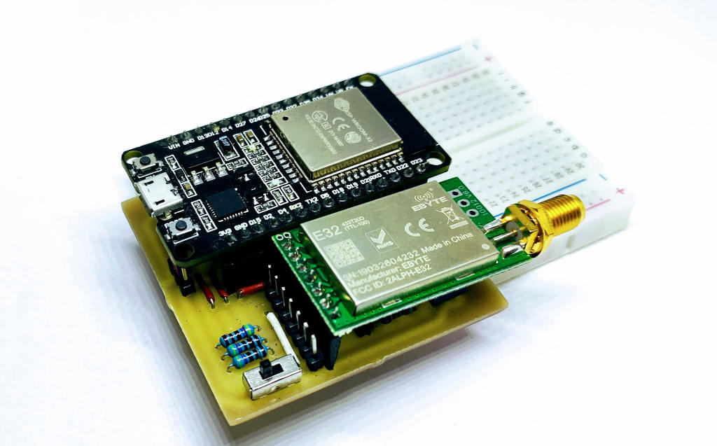
ESP32 DOIT DEV KIT v1 shield v1
I will also create a shield for esp32 which is very useful for prototyping.
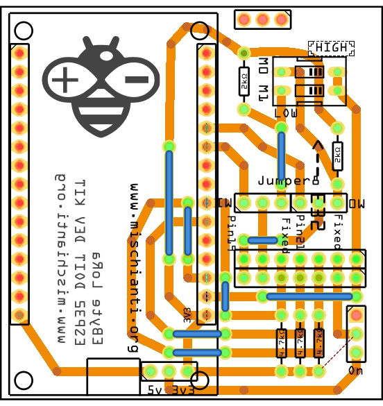
The configuration is this:
LoRa_E32 e32ttl(&Serial2, 15, 21, 19);
Than you can use all examples inside the library, you can use pin GPIO21 and GPIO19 to do a full connection or disable they and put M0 and M1 as you want with dipswitch.
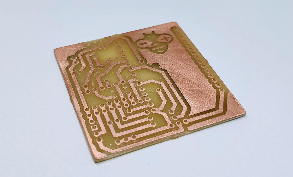
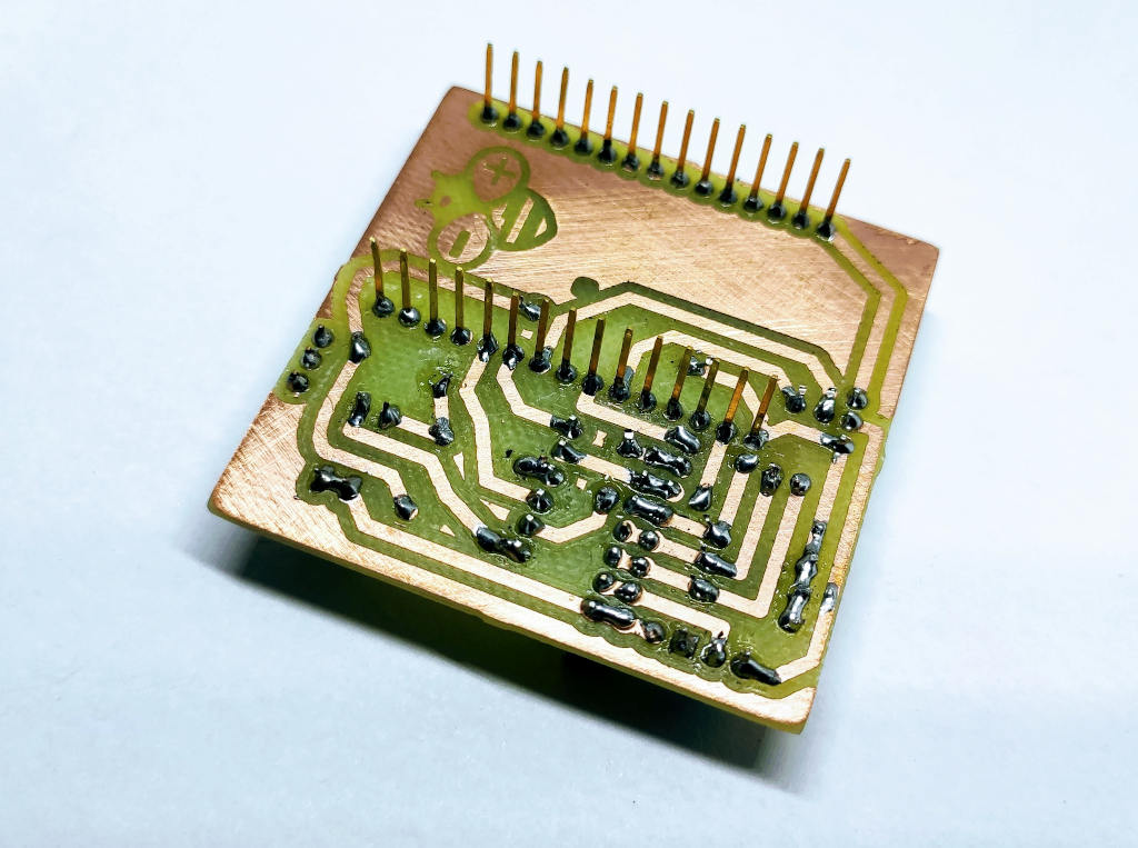
Now we are going to soldering.
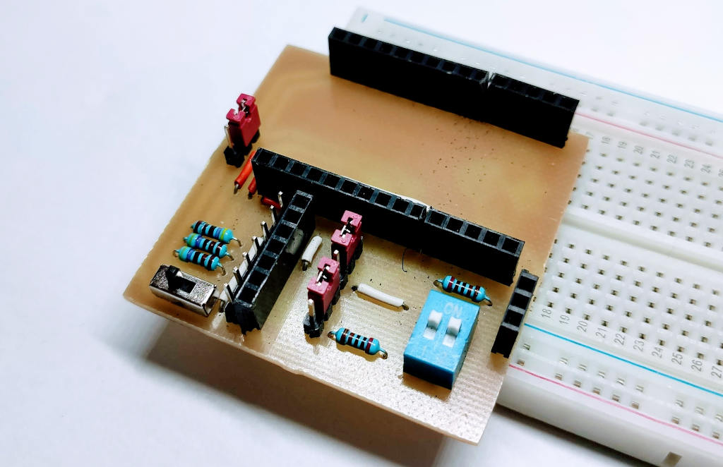
Here the result of milled PCB
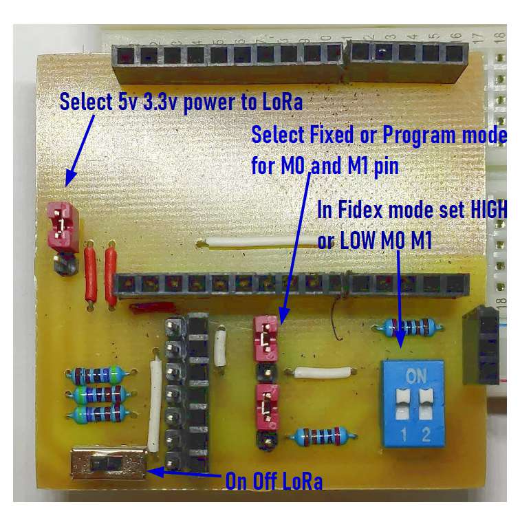
The shield have some jumper and dip switch to configure M0 and M1.
If you want set M0 and M1 to a fixed value you must put jumper to F, if you want control via pin to P.
If you set to F you must put dip switch on property value Low or High.
New versione shared v3
Now I put the open source PCB on free hosting of PCBWay, the “evolved” PCB is this:
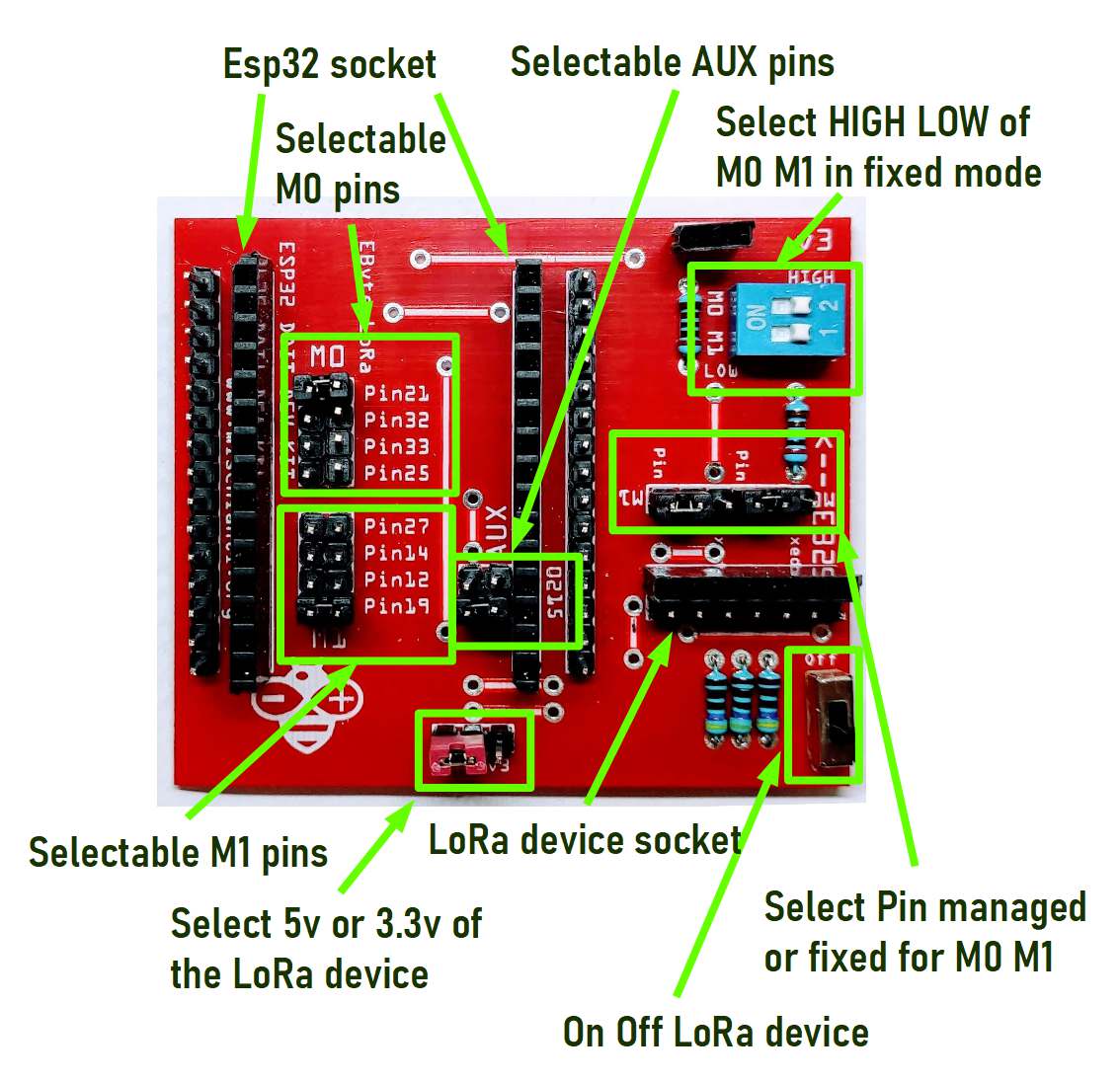
Order the PCB (you can order from PCBWay 5$ for 10pcs) PCBWay

Shopping List
You can find the LoRa devices here on AliExpress (433MHz 5Km) - AliExpress (433MHz 8Km) - AliExpress (433MHz 16Km) - AliExpress (868MHz 915MHz 5.5Km) - AliExpress (868MHz 915MHz 8Km)
You can find the ESP32 DEV KIT here on ESP32 Dev Kit v1 - TTGO T-Display 1.14 ESP32 - NodeMCU V3 V2 ESP8266 Lolin32 - NodeMCU ESP-32S - WeMos Lolin32 - WeMos Lolin32 mini - ESP32-CAM programmer - ESP32-CAM bundle - ESP32-WROOM-32 - ESP32-S
| Amount | Part Type | Properties |
|---|---|---|
| 1 | Lora E32-TTL-100 | variant 1; voltage 3-5V; type Basic |
| 1 | DIP SWITCH | channels 1; package dipswitch-02 |
| 2 | Generic male header – 3 pins | pins 3; pin spacing 0.1in (2.54mm); hole size 1.0mm,0.508mm; form ♂ (male); package THT; row single |
| 1 | ESP32 DOIT DEVKIT v1 | type esp8266 |
| 3 | 4.7kΩ Resistor | bands 4; tolerance ±5%; pin spacing 400 mil; package THT; resistance 4.7kΩ |
| 3 | 2kΩ Resistor | bands 4; tolerance ±5%; pin spacing 400 mil; package THT; resistance 2kΩ |
| Generic female header | Pin spacing 0.1in (2.54mm); | |
| Generic male/female header | Pin spacing 0.1in (2.54mm); |
You can get pcb without additional costs here from PCBWay
I chose this manufacturer because at the same cost it offers excellent quality, in the first screen it is possible to make countless options suitable for every need.

The board as you can see on various photo is very beautiful and simply to solder.
Here the soldering video of the version 1 of the PCB.
Thanks
- LoRa E32 device for Arduino, esp32 or esp8266: settings and basic usage
- LoRa E32 device for Arduino, esp32 or esp8266: library
- LoRa E32 device for Arduino, esp32 or esp8266: configuration
- LoRa E32 device for Arduino, esp32 or esp8266: fixed transmission
- LoRa E32 device for Arduino, esp32 or esp8266: power saving and sending structured data
- LoRa E32 device for Arduino, esp32 or esp8266: WOR (wake on radio) microcontroller and Arduino shield
- LoRa E32 device for Arduino, esp32 or esp8266: WOR (wake on radio) microcontroller and WeMos D1 shield
- EByte LoRa E32 device for Arduino, esp32 or esp8266: WOR (wake on radio) and new ESP32 shield
- Ebyte LoRa E32 with STM32: WOR (wake on radio) and new STM32 shield
- Mischianti Arduino LoRa shield (Open source)
- Mischianti WeMos LoRa shield (Open source)
- Mischianti ESP32 DOIT DEV KIT v1 shield (Open source)
- STM32F1 Blue-Pill EByte LoRa E32, E22, and E220 Shield
- STM32F4 Black-Pill EByte LoRa E32, E22, and E220 Shield


I can’t for the life of me get either the E220 or E32 working with an ESP32, I have followed your diagrams exactly but both devices and libraries just give “No response from device!”. I have tried both with 3.3V and 5V VCC input, on several different brand ESP32 boards. If it is the case that external power must be supplied, then that is unfortunate and unsuitable for my needs. How did you manage to get this working without external?
Hi Kriss,
It’s possible that the problem is the external power supply if you supply 5v to your esp32 and LoRa module, and you need more amperage.
It’s important also to specify which module you have; naturally, you can’t power an EByte E220 with 30dbm (10Km range) with a half ampere.
Bye Renzo