Unleashing IoT Potential: Integrating STM32F4 Black-Pill with EByte LoRa E32, E22, and E220 Shield
In the rapidly expanding world of the Internet of Things (IoT), long-range and low-power communication technologies are becoming increasingly crucial. One such technology, known as LoRa (Long Range), has emerged as a leading solution, thanks to its ability to facilitate extensive, low-energy communication between IoT devices.
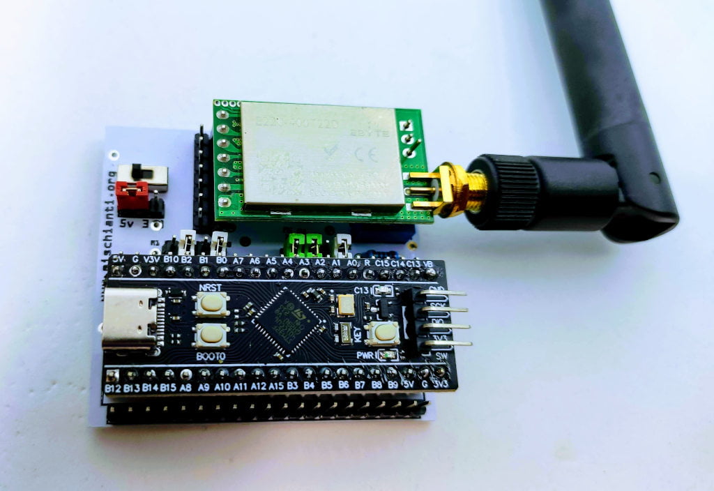
The STM32F4 Black-Pill, a powerful and versatile microcontroller, offers promising potential for IoT applications when integrated with LoRa modules like EByte’s E32, E22, and E220. In this article, we’ll examine the Shield I use for rapid prototyping that supports all the LoRa modules described.
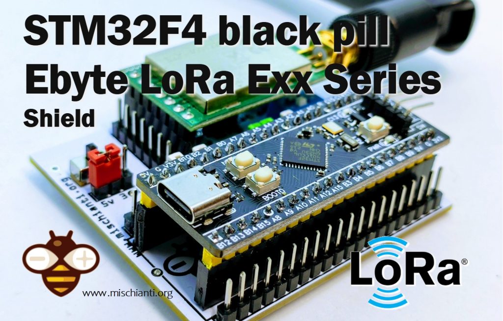
So here is a prototype board to develop the LoRa application. As usual, I use EByte modules, and this board is fully compatible with E32, E22, and E220.
STM32F4 black-pill pinout
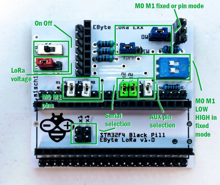
As you can see in the pinout diagram you can find more than one Serial interface. In this board, I add jumpers to select Serial1 (Tx -> PA9, Rx->PA10) and Serial2 (Tx -> PA2, and Rx->PA3) interface.
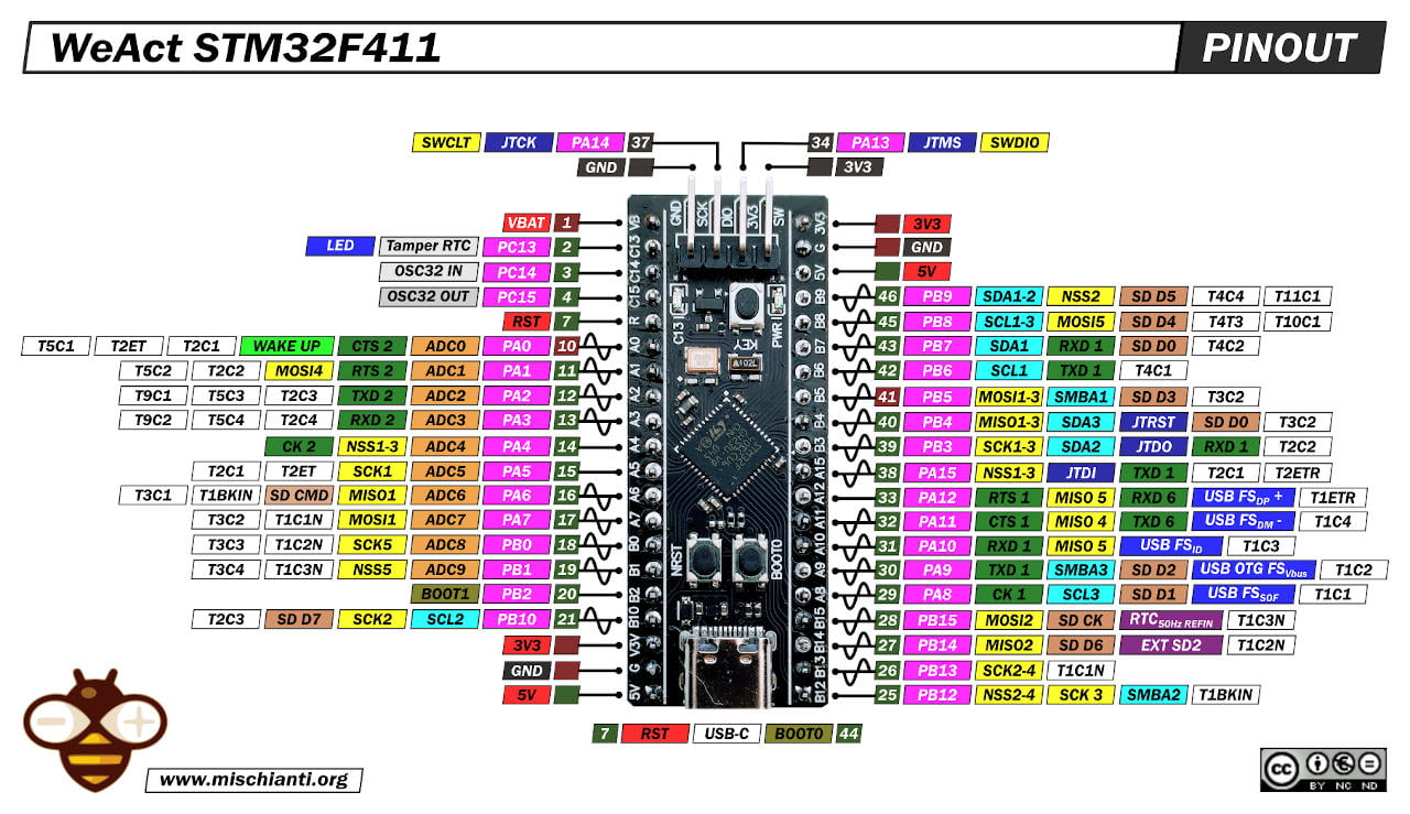
The selectable pins are also AUX, M0 and M1.
Here my selection of STM32 STM32F103C8T6 STM32F401 STM32F411 ST-Link v2 ST-Link v2 official
For AUX I put PA0 (or WAKE pin) and PA1, for M0 you can select B0 and B1, for M1 the B2 and B10.
You can also put M0 and M1 in fixed mode and select the static status in the DIP-switch.
PCB
You can order the PCB from PCBWay for few dollars PCBWay

As usual, I create a PCB that can be milled, so when I send It to the factory for production, I’m sure that it works correctly.
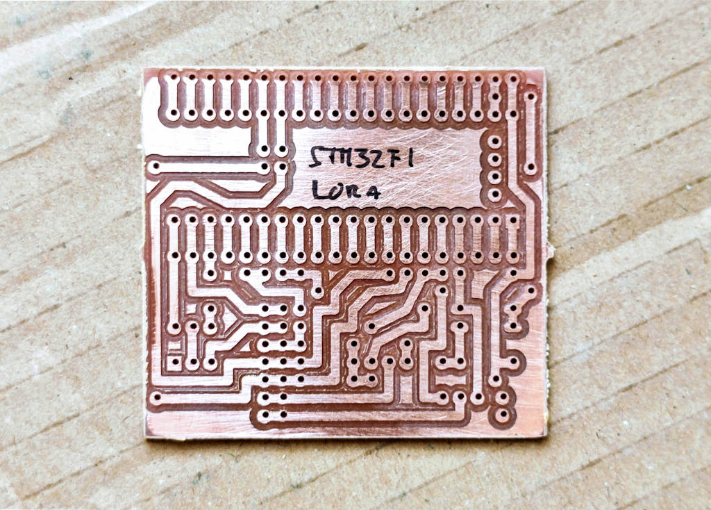
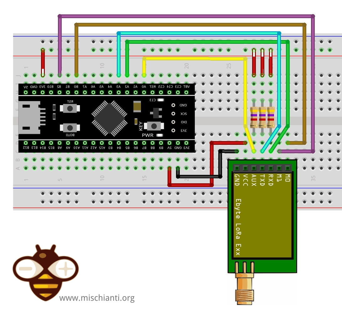
The design is quite simple, you can check the connection in the PCB schema:
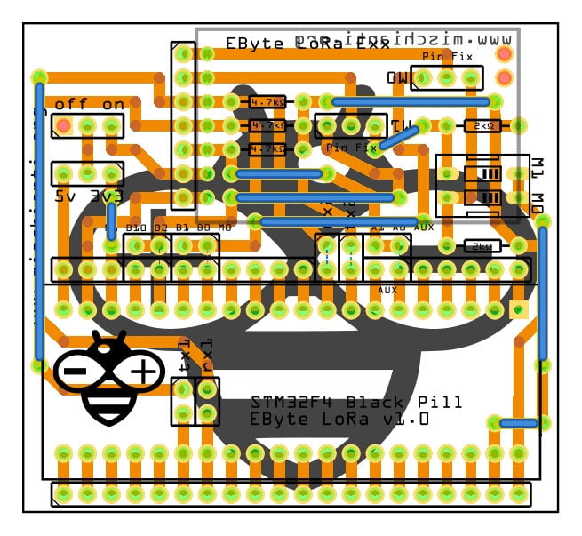
The standard configuration is:
HardwareSerial Serial2(USART2);   // PA3  (RX)  PA2  (TX)
LoRa_E32 e32ttl(&Serial2, PA0, PB0, PB10); //  Serial2 AUX M0 M1
But, as already described, you can select with the jumpers other configuration:
- Serial1 (
Tx->PA9, Rx->PA10) or Serial2 (Tx->PA2, Rx->PA3); AUXwithPA0(or WAKE pin) andPA1;M0you can selectB0andB1;M1you can selectB2andB10.
Here is the PCB description to better understand.
Shopping List
EByte LoRa E32 AliExpress (433MHz 5Km) - AliExpress (433MHz 8Km) - AliExpress (433MHz 16Km) - AliExpress (868MHz 915MHz 5.5Km) - AliExpress (868MHz 915MHz 8Km)
EByte LoRa E22 AliExpress (433MHz 5.5Km) - AliExpress (433MHz 10Km) - AliExpress (868MHz 915Mhz 5.5Km) - AliExpress (868MHz 915Mhz 10Km)
EByte LoRa E220 E220-400T22D 433MHz 5Km - E220-400T30D 433MHz 10Km - E220-900T22D 868MHz 915MHz 5Km - E220-900T30D 868MHz 915MHz 10Km
Amount Part Type Properties 1 Lora Exx variant 1; voltage 3-5V; type Basic 1 DIP SWITCH channels 1; package dipswitch-02 2 Generic male header – 3 pins pins 3; pin spacing 0.1in (2.54mm); hole size 1.0mm,0.508mm; form ♂ (male); package THT; row single 3 4.7kΩ Resistor bands 4; tolerance ±5%; pin spacing 400 mil; package THT; resistance 4.7kΩ 3 2kΩ Resistor bands 4; tolerance ±5%; pin spacing 400 mil; package THT; resistance 2kΩ Generic female header Pin spacing 0.1in (2.54mm); Generic male/female header Pin spacing 0.1in (2.54mm);
Configuration and test (Arduino & MicroPython)
I’m going to show a simple sketch to get the configuration of an EByte LoRa E220. First of all, remember to set the correct constructor with the correct selection of the pin.
/*
 * LoRa E220
 * Get configuration.
 * You must uncommend the correct constructor.
 *
 * by Renzo Mischianti <https://mischianti.org>
 *
 * https://mischianti.org
 *
 * E220		  ----- WeMos D1 mini	----- esp32			----- Arduino Nano 33 IoT	----- Arduino MKR	----- Raspberry Pi Pico   ----- stm32               ----- ArduinoUNO
 * M0         ----- D7 (or 3.3v)	----- 19 (or 3.3v)	----- 4 (or 3.3v)			----- 2 (or 3.3v)	----- 10 (or 3.3v)	      ----- PB0 (or 3.3v)       ----- 7 Volt div (or 3.3v)
 * M1         ----- D6 (or 3.3v)	----- 21 (or 3.3v)	----- 6 (or 3.3v)			----- 4 (or 3.3v)	----- 11 (or 3.3v)	      ----- PB10 (or 3.3v)      ----- 6 Volt div (or 3.3v)
 * TX         ----- D3 (PullUP)		----- TX2 (PullUP)	----- TX1 (PullUP)			----- 14 (PullUP)	----- 8 (PullUP)	      ----- PA2 TX2 (PullUP)    ----- 4 (PullUP)
 * RX         ----- D4 (PullUP)		----- RX2 (PullUP)	----- RX1 (PullUP)			----- 13 (PullUP)	----- 9 (PullUP)	      ----- PA3 RX2 (PullUP)    ----- 5 Volt div (PullUP)
 * AUX        ----- D5 (PullUP)		----- 18  (PullUP)	----- 2  (PullUP)			----- 0  (PullUP)	----- 2  (PullUP)	      ----- PA0  (PullUP)       ----- 3 (PullUP)
 * VCC        ----- 3.3v/5v			----- 3.3v/5v		----- 3.3v/5v				----- 3.3v/5v		----- 3.3v/5v		      ----- 3.3v/5v             ----- 3.3v/5v
 * GND        ----- GND				----- GND			----- GND					----- GND			----- GND			      ----- GND                 ----- GND
 *
 */

#include "Arduino.h"
#include "LoRa_E220.h"

// ---------- esp8266 pins --------------
//LoRa_E220 e220ttl(RX, TX, AUX, M0, M1);  // Arduino RX <-- e220 TX, Arduino TX --> e220 RX
//LoRa_E220 e220ttl(D3, D4, D5, D7, D6); // Arduino RX <-- e220 TX, Arduino TX --> e220 RX AUX M0 M1
//LoRa_E220 e220ttl(D2, D3); // Config without connect AUX and M0 M1

//#include <SoftwareSerial.h>
//SoftwareSerial mySerial(D2, D3); // Arduino RX <-- e220 TX, Arduino TX --> e220 RX
//LoRa_E220 e220ttl(&mySerial, D5, D7, D6); // AUX M0 M1
// -------------------------------------

// ---------- Arduino pins --------------
//LoRa_E220 e220ttl(4, 5, 3, 7, 6); // Arduino RX <-- e220 TX, Arduino TX --> e220 RX AUX M0 M1
//LoRa_E220 e220ttl(4, 5); // Config without connect AUX and M0 M1

//#include <SoftwareSerial.h>
//SoftwareSerial mySerial(4, 5); // Arduino RX <-- e220 TX, Arduino TX --> e220 RX
//LoRa_E220 e220ttl(&mySerial, 3, 7, 6); // AUX M0 M1
// -------------------------------------

// ------------- Arduino Nano 33 IoT -------------
// LoRa_E220 e220ttl(&Serial1, 2, 4, 6); //  RX AUX M0 M1
// -------------------------------------------------

// ------------- Arduino MKR WiFi 1010 -------------
// LoRa_E220 e220ttl(&Serial1, 0, 2, 4); //  RX AUX M0 M1
// -------------------------------------------------

// ---------- esp32 pins --------------
// LoRa_E220 e220ttl(&Serial2, 15, 21, 19); //  RX AUX M0 M1

//LoRa_E220 e220ttl(&Serial2, 22, 4, 18, 21, 19, UART_BPS_RATE_9600); //  esp32 RX <-- e220 TX, esp32 TX --> e220 RX AUX M0 M1
// -------------------------------------

// ---------- Raspberry PI Pico pins --------------
// LoRa_E220 e220ttl(&Serial2, 2, 10, 11); //  RX AUX M0 M1
// -------------------------------------

// ---------------- STM32 --------------------
HardwareSerial Serial2(USART2);   // PA3  (RX)  PA2  (TX)
LoRa_E220 e220ttl(&Serial2, PA0, PB0, PB10); //  RX AUX M0 M1
// -------------------------------------------------

void printParameters(struct Configuration configuration);
void printModuleInformation(struct ModuleInformation moduleInformation);

void setup() {
	Serial.begin(9600);
	while(!Serial){};
	delay(500);

	Serial.println();


	// Startup all pins and UART
	e220ttl.begin();

	ResponseStructContainer c;
	c = e220ttl.getConfiguration();
	// It's important get configuration pointer before all other operation
	Configuration configuration = *(Configuration*) c.data;
	Serial.println(c.status.getResponseDescription());
	Serial.println(c.status.code);

	printParameters(configuration);

	ResponseStructContainer cMi;
	cMi = e220ttl.getModuleInformation();
	// It's important get information pointer before all other operation
	ModuleInformation mi = *(ModuleInformation*)cMi.data;

	Serial.println(cMi.status.getResponseDescription());
	Serial.println(cMi.status.code);

	printModuleInformation(mi);
}

void loop() {

}
void printParameters(struct Configuration configuration) {
	Serial.println("----------------------------------------");

	Serial.print(F("HEAD : "));  Serial.print(configuration.COMMAND, HEX);Serial.print(" ");Serial.print(configuration.STARTING_ADDRESS, HEX);Serial.print(" ");Serial.println(configuration.LENGHT, HEX);
	Serial.println(F(" "));
	Serial.print(F("AddH : "));  Serial.println(configuration.ADDH, HEX);
	Serial.print(F("AddL : "));  Serial.println(configuration.ADDL, HEX);
	Serial.println(F(" "));
	Serial.print(F("Chan : "));  Serial.print(configuration.CHAN, DEC); Serial.print(" -> "); Serial.println(configuration.getChannelDescription());
	Serial.println(F(" "));
	Serial.print(F("SpeedParityBit     : "));  Serial.print(configuration.SPED.uartParity, BIN);Serial.print(" -> "); Serial.println(configuration.SPED.getUARTParityDescription());
	Serial.print(F("SpeedUARTDatte     : "));  Serial.print(configuration.SPED.uartBaudRate, BIN);Serial.print(" -> "); Serial.println(configuration.SPED.getUARTBaudRateDescription());
	Serial.print(F("SpeedAirDataRate   : "));  Serial.print(configuration.SPED.airDataRate, BIN);Serial.print(" -> "); Serial.println(configuration.SPED.getAirDataRateDescription());
	Serial.println(F(" "));
	Serial.print(F("OptionSubPacketSett: "));  Serial.print(configuration.OPTION.subPacketSetting, BIN);Serial.print(" -> "); Serial.println(configuration.OPTION.getSubPacketSetting());
	Serial.print(F("OptionTranPower    : "));  Serial.print(configuration.OPTION.transmissionPower, BIN);Serial.print(" -> "); Serial.println(configuration.OPTION.getTransmissionPowerDescription());
	Serial.print(F("OptionRSSIAmbientNo: "));  Serial.print(configuration.OPTION.RSSIAmbientNoise, BIN);Serial.print(" -> "); Serial.println(configuration.OPTION.getRSSIAmbientNoiseEnable());
	Serial.println(F(" "));
	Serial.print(F("TransModeWORPeriod : "));  Serial.print(configuration.TRANSMISSION_MODE.WORPeriod, BIN);Serial.print(" -> "); Serial.println(configuration.TRANSMISSION_MODE.getWORPeriodByParamsDescription());
	Serial.print(F("TransModeEnableLBT : "));  Serial.print(configuration.TRANSMISSION_MODE.enableLBT, BIN);Serial.print(" -> "); Serial.println(configuration.TRANSMISSION_MODE.getLBTEnableByteDescription());
	Serial.print(F("TransModeEnableRSSI: "));  Serial.print(configuration.TRANSMISSION_MODE.enableRSSI, BIN);Serial.print(" -> "); Serial.println(configuration.TRANSMISSION_MODE.getRSSIEnableByteDescription());
	Serial.print(F("TransModeFixedTrans: "));  Serial.print(configuration.TRANSMISSION_MODE.fixedTransmission, BIN);Serial.print(" -> "); Serial.println(configuration.TRANSMISSION_MODE.getFixedTransmissionDescription());


	Serial.println("----------------------------------------");
}
void printModuleInformation(struct ModuleInformation moduleInformation) {
	Serial.println("----------------------------------------");
	Serial.print(F("HEAD: "));  Serial.print(moduleInformation.COMMAND, HEX);Serial.print(" ");Serial.print(moduleInformation.STARTING_ADDRESS, HEX);Serial.print(" ");Serial.println(moduleInformation.LENGHT, DEC);

	Serial.print(F("Model no.: "));  Serial.println(moduleInformation.model, HEX);
	Serial.print(F("Version  : "));  Serial.println(moduleInformation.version, HEX);
	Serial.print(F("Features : "));  Serial.println(moduleInformation.features, HEX);
	Serial.println("----------------------------------------");
}
And here is the Serial output.
Success
1
----------------------------------------
HEAD : C1 0 8

AddH : 0
AddL : 3

Chan : 23 -> 433MHz

SpeedParityBit     : 0 -> 8N1 (Default)
SpeedUARTDatte     : 11 -> 9600bps (default)
SpeedAirDataRate   : 10 -> 2.4kbps (default)

OptionSubPacketSett: 0 -> 200bytes (default)
OptionTranPower    : 0 -> 22dBm (Default)
OptionRSSIAmbientNo: 0 -> Disabled (default)

TransModeWORPeriod : 11 -> 2000ms (default)
TransModeEnableLBT : 0 -> Disabled (default)
TransModeEnableRSSI: 0 -> Disabled (default)
TransModeFixedTrans: 1 -> Fixed transmission (first three bytes can be used as high/low address and channel)
----------------------------------------
Success
1
----------------------------------------
HEAD: C1 8 3
Model no.: 13
Version  : A
Features : 16
----------------------------------------
Now for MicroPython, another simple sketch
# Author: Renzo Mischianti
# Website: www.mischianti.org
#
# Description:
# This script initializes the E220 LoRa module with MicroPython,
# retrieves the current configuration, and prints it to the console.
# The code demonstrates how to use the LoRaE32 library to interact with the module and read its configuration.
#

from machine import UART

from lora_e220 import LoRaE220, print_configuration
from lora_e220_operation_constant import ResponseStatusCode

# uart2 = UART(2)
# lora = LoRaE220('400T22D', uart2, aux_pin=15, m0_pin=21, m1_pin=19)
# STM32F411CEU6 Shield
uart2 = UART(2)
lora = LoRaE220('400T22D', uart2, aux_pin='PA0', m0_pin='PB0', m1_pin='PB2')

code = lora.begin()
print("Initialization: {}", ResponseStatusCode.get_description(code))

code, configuration = lora.get_configuration()

print("Retrieve configuration: {}", ResponseStatusCode.get_description(code))

print_configuration(configuration)
Thanks
- STM32F1 Blue-Pill: pinout, specs, and Arduino IDE configuration (STM32duino and STMicroelectronics)
- STM32: program (STM32F1) via USB with STM32duino bootloader
- STM32: programming (STM32F1 STM32F4) via USB with HID boot-loader
- STM32F4 Black-Pill: pinout, specs, and Arduino IDE configuration
- STM32: ethernet w5500 with plain HTTP and SSL (HTTPS)
- STM32: ethernet enc28j60 with plain HTTP and SSL (HTTPS)
- STM32: WiFiNINA with ESP32 WiFi Co-Processor
- How to use SD card with stm32 and SdFat library
- \STM32: SPI flash memory FAT FS
- STM32: internal RTC, clock, and battery backup (VBAT)
- STM32 LoRa
- STM32 Power saving
- STM32F1 Blue-Pill clock and frequency management
- STM32F4 Black-Pill clock and frequency management
- Intro and Arduino vs STM framework
- Library LowPower, wiring, and Idle (STM Sleep) mode
- Sleep, deep sleep, shutdown, and power consumption
- Wake up from RTC alarm and Serial
- Wake up from the external source
- Backup domain intro and variable preservation across reset
- RTC backup register and SRAM preservation
- STM32 send emails with attachments and SSL (like Gmail): w5500, enc28j60, SD, and SPI Fash
- FTP server on STM32 with w5500, enc28j60, SD Card, and SPI Flash
- Connecting the EByte E70 to STM32 (black/blue pill) devices and a simple sketch example