STM32 power saving: wake up from external source – 7
After the timed, alarm and Serial wake-up, the most used one is the wake-up via an external source. In this case, we must pay attention to the pinout of our device to select the correct pin in the correct situation.
One of the most common situations is the wake-up from an external source. In this case, we configure a button.
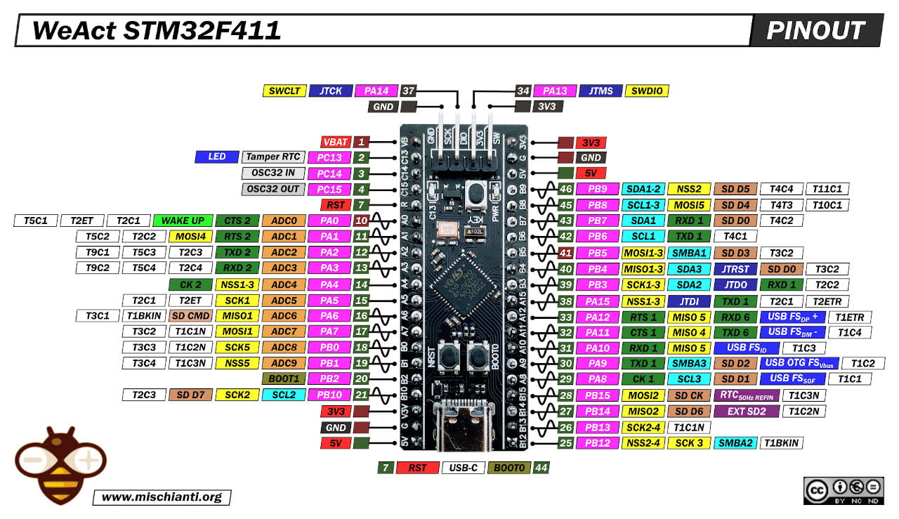
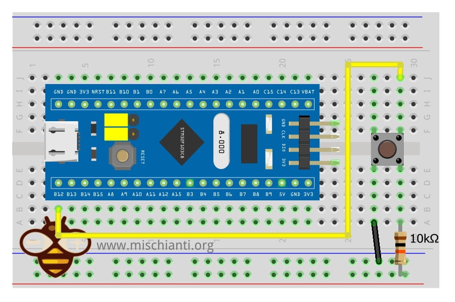
For the first test, we configure PB12 pin as an INPUT_PULLUP input with a simple push-button with a pull-up resistor, so It works on push release (RAISING interrupt).
STM32 external interrupt controller (deep-sleep wake-up)
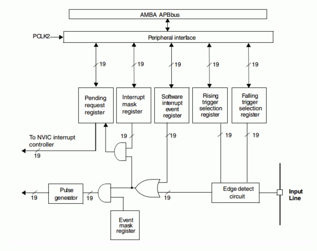
Each IO of STM32 can be used as an external interrupt input. EXTI (External interrupt/event controller) manages 20 interrupt/event lines of the controller. Each interrupt/event line corresponds to an edge detector, which can detect the rising edge and falling edge of the input signal. EXTI can configure each interrupt / event line separately, as an interrupt or event, and the attributes of the trigger event.
External interrupt line
The interrupt controller of STM32 supports 19 external interrupts and event requests (that is, 19 external interrupt lines). Each interrupt is equipped with status bits, and each interrupt / event has independent trigger and mask settings. The 19 external interrupts of STM32 correspond to 19 medium break lines:
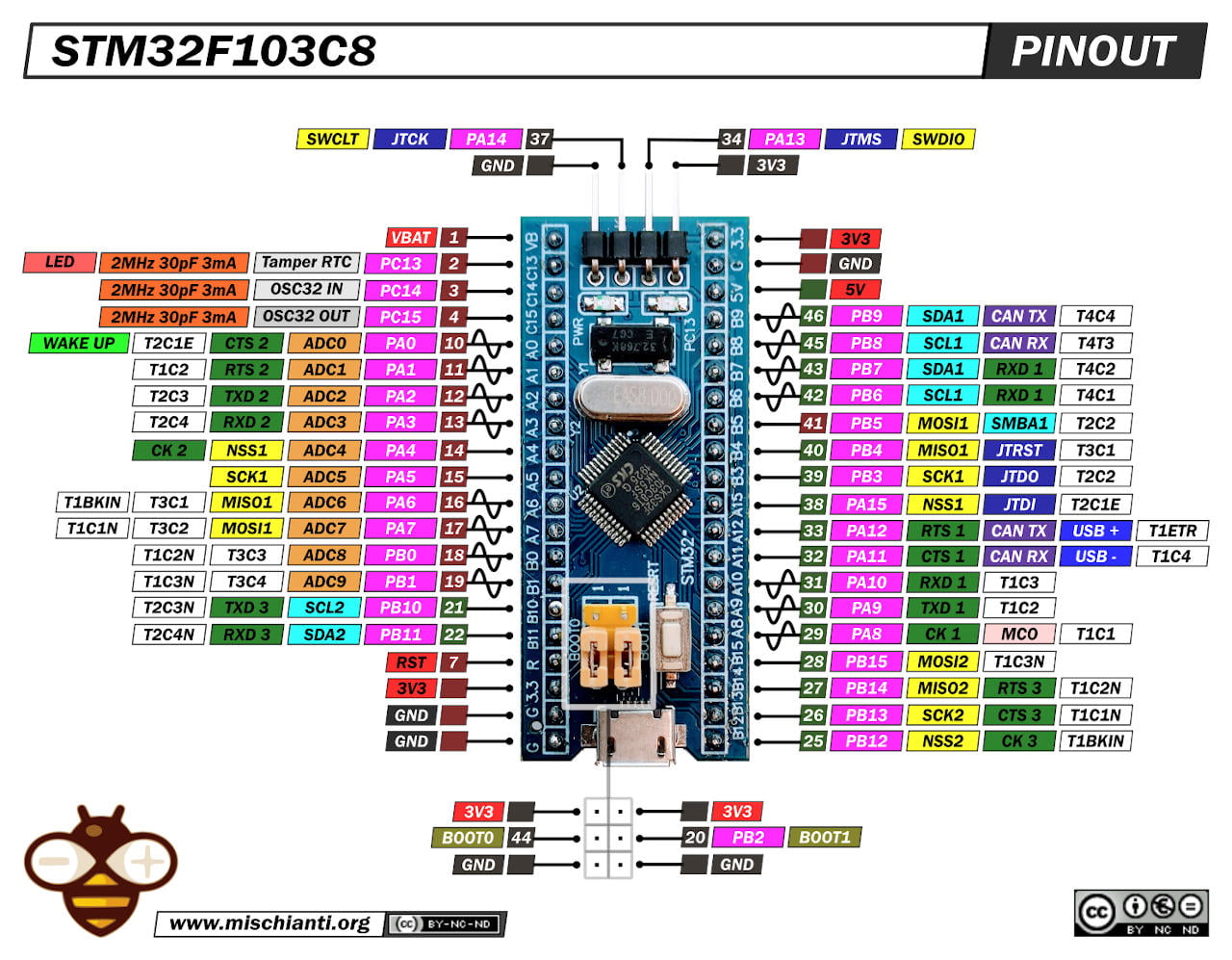
- Line 0~15: input interrupt corresponding to external IO port;
- Line 16: connected to PVD output;
- Line 17: connected to RTC alarm clock event;
- Line 18: connect to USB wake-up event.
EXTI Controller Features
The EXTI controller main features are the following:
- Independent trigger and mask on each interrupt/event line
- Dedicated status bit for each interrupt line
- Generation of up to 20 software event/interrupt requests
- Detection of external signal with pulse width lower than the APB2 clock period.
EXTI Block Diagram
Wiring wake-up pin
Here the STM32 and ST-Link V2 used in this test STM32F103C8T6 STM32F401 STM32F411 ST-Link v2 ST-Link v2 official
Here the FTDI USB to TTL CH340G - USB to TTL FT232RL
Here my multimeter Aneng SZ18
Deep Sleep wake-up
Now a simple sketch:
/**
 *	External wake up
 *
 *	In this sketch we put the STM32 on Deep Sleep than wake up It via
 *	a button.
 *	If present we use on board PB12 button, not suitable for shutdown
 *
 *	Renzo Mischianti <www.mischianti.org>
 * en: https://mischianti.org/category/tutorial/stm32-tutorial/
 * it: https://mischianti.org/it/category/guide/guida-alla-linea-di-microcontrollori-stm32/
 */

#include "STM32LowPower.h"

volatile int wakeUpCount = 1;

const int pin = PB12;

void wakedUp();

void setup() {
  Serial.begin(115200);

  pinMode(pin, INPUT_PULLUP);

  // Configure low power
  LowPower.begin();
  // Attach a wakeup interrupt on pin, calling repetitionsIncrease when the device is woken up
  // Last parameter (LowPowerMode) should match with the low power state used: in this example LowPower.sleep()
  LowPower.attachInterruptWakeup(pin, wakedUp, RISING, DEEP_SLEEP_MODE);

  Serial.println("Start low-power mode!");
  delay(1000);

  LowPower.deepSleep();

  delay(1000);
  Serial.print("Exit low-power mode! ");
  Serial.println(wakeUpCount);
}

void loop() {
	delay(100);
}

void wakedUp() {
	// This function will be called once on device wakeup
	// You can do some little operations here (like changing variables which will be used in the loop)
	// Remember to avoid calling delay() and long running functions since this functions executes in interrupt context

	Serial.println("Waked!");

	wakeUpCount ++;
}
The serial output is:
Start low-power mode!
Waked!
Exit low-power mode! 2
Where the highlighted part is before the key release of the button.
You must pay attention to the parameter of attachInterruptWakeup function.
LowPower.attachInterruptWakeup(pin, wakedUp, RISING, DEEP_SLEEP_MODE);
It’s important the set the last parameter with the current LowPower mode selected, the possible values are:
enum LP_Mode : uint8_t {
  IDLE_MODE,
  SLEEP_MODE,
  DEEP_SLEEP_MODE,
  SHUTDOWN_MODE
};
Pay attention, if you use an STM32F4 Black-Pill the on board button doesn’t have the pull-up resistor.
If you want, you can substitute LowPower.deepSleep(); with the other LowPower modes.
LowPower.idle();LowPower.sleep();LowPower.shutdown();
Shutdown/Standby wake-up
If you try to use the upper code with shutdown you get a bad surprise, It doesn’t wake. For shutdown (or Standby) you can’t use the standard pin, you must use the wake-up pin.
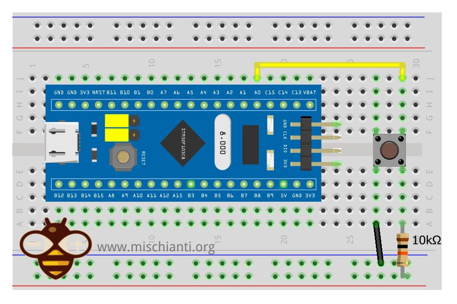
For STM32F1 and STM32F4 It’s PA0, but you can refer to It with SYS_WKUP1. We are going to do some changes to the sketch to perform the same check and fix.
/**
 *	External wake up
 *
 *	In this sketch we put the STM32 on shutdown than wake up It via
 *	a button.
 *	If present we use on board PA0 button (add pull-up), else set the primary
 *	System Wake Up button.
 *
 *	Renzo Mischianti <www.mischianti.org>
 * en: https://mischianti.org/category/tutorial/stm32-tutorial/
 * it: https://mischianti.org/it/category/guide/guida-alla-linea-di-microcontrollori-stm32/
 */

#include "STM32LowPower.h"
#include <STM32RTC.h>

// Pin used to trigger a wakeup
#ifndef USER_BTN
#define USER_BTN SYS_WKUP1
#endif

const int pin = USER_BTN;

void wakedUp();
bool isWakeUpPin(uint32_t pin, uint32_t mode = RISING);

void setup() {
  Serial.begin(115200);
  delay(1000);

  Serial.println("START PROGRAM!");

  pinMode(pin, INPUT_PULLUP);

  if (!isWakeUpPin(pin)) {
	  Serial.println("For Shutdown we need a wake-up pin! Check the pinout!");
	  while (true) { delay(1000); }
  }

  // Configure low power
  LowPower.begin();
  // Attach a wakeup interrupt on pin, calling repetitionsIncrease when the device is woken up
  // Last parameter (LowPowerMode) should match with the low power state used: in this example LowPower.sleep()
  LowPower.attachInterruptWakeup(pin, wakedUp, RISING, SHUTDOWN_MODE);

  Serial.println("Start shutdown mode in ");
  for (int i = 10;i>0;i--) { Serial.print(i); Serial.print(" "); } Serial.println( "OK!" );
  delay(1000);

  LowPower.shutdown();

  delay(1000);
}

void loop() {
	delay(100);
}

void wakedUp() {
	// randomly you can read this, but normally reset block every time the execution
	Serial.println("Wake-Up callback!");
}

bool isWakeUpPin(uint32_t pin, uint32_t mode)
{
  uint32_t wkup_pin = 0;
  PinName p = digitalPinToPinName(pin);
  if (p != NC) {
#ifdef PWR_WAKEUP_PIN1
    if ((p == SYS_WKUP1)
#ifdef PWR_WAKEUP_PIN1_1
        || (p == SYS_WKUP1_1)
#endif
#ifdef PWR_WAKEUP_PIN1_2
        || (p == SYS_WKUP1_2)
#endif
       ) {
      wkup_pin = PWR_WAKEUP_PIN1;
#ifdef PWR_WAKEUP_PIN1_HIGH
      if (mode != RISING) {
        wkup_pin = PWR_WAKEUP_PIN1_LOW;
      }
#endif
    }
#endif /* PWR_WAKEUP_PIN1 */
#ifdef PWR_WAKEUP_PIN2
    if ((p == SYS_WKUP2)
#ifdef PWR_WAKEUP_PIN2_1
        || (p == SYS_WKUP2_1)
#endif
#ifdef PWR_WAKEUP_PIN2_2
        || (p == SYS_WKUP2_2)
#endif
       ) {
      wkup_pin = PWR_WAKEUP_PIN2;
#ifdef PWR_WAKEUP_PIN2_HIGH
      if (mode != RISING) {
        wkup_pin = PWR_WAKEUP_PIN2_LOW;
      }
#endif
    }
#endif /* PWR_WAKEUP_PIN2 */
#ifdef PWR_WAKEUP_PIN3
    if ((p == SYS_WKUP3)
#ifdef PWR_WAKEUP_PIN3_1
        || (p == SYS_WKUP3_1)
#endif
#ifdef PWR_WAKEUP_PIN3_2
        || (p == SYS_WKUP3_2)
#endif
       ) {
      wkup_pin = PWR_WAKEUP_PIN3;
#ifdef PWR_WAKEUP_PIN3_HIGH
      if (mode != RISING) {
        wkup_pin = PWR_WAKEUP_PIN3_LOW;
      }
#endif
    }
#endif /* PWR_WAKEUP_PIN3 */
#ifdef PWR_WAKEUP_PIN4
    if ((p == SYS_WKUP4)
#ifdef PWR_WAKEUP_PIN4_1
        || (p == SYS_WKUP4_1)
#endif
#ifdef PWR_WAKEUP_PIN4_2
        || (p == SYS_WKUP4_2)
#endif
       ) {
      wkup_pin = PWR_WAKEUP_PIN4;
#ifdef PWR_WAKEUP_PIN4_HIGH
      if (mode != RISING) {
        wkup_pin = PWR_WAKEUP_PIN4_LOW;
      }
#endif
    }
#endif /* PWR_WAKEUP_PIN4 */
#ifdef PWR_WAKEUP_PIN5
    if ((p == SYS_WKUP5)
#ifdef PWR_WAKEUP_PIN5_1
        || (p == SYS_WKUP5_1)
#endif
#ifdef PWR_WAKEUP_PIN5_2
        || (p == SYS_WKUP5_2)
#endif
       ) {
      wkup_pin = PWR_WAKEUP_PIN5;
#ifdef PWR_WAKEUP_PIN5_HIGH
      if (mode != RISING) {
        wkup_pin = PWR_WAKEUP_PIN5_LOW;
      }
#endif
    }
#endif /* PWR_WAKEUP_PIN5 */
#ifdef PWR_WAKEUP_PIN6
    if ((p == SYS_WKUP6)
#ifdef PWR_WAKEUP_PIN6_1
        || (p == SYS_WKUP6_1)
#endif
#ifdef PWR_WAKEUP_PIN6_2
        || (p == SYS_WKUP6_2)
#endif
       ) {
      wkup_pin = PWR_WAKEUP_PIN6;
#ifdef PWR_WAKEUP_PIN6_HIGH
      if (mode != RISING) {
        wkup_pin = PWR_WAKEUP_PIN6_LOW;
      }
#endif
    }
#endif /* PWR_WAKEUP_PIN6 */
#ifdef PWR_WAKEUP_PIN7
    if ((p == SYS_WKUP7)
#ifdef PWR_WAKEUP_PIN7_1
        || (p == SYS_WKUP7_1)
#endif
#ifdef PWR_WAKEUP_PIN7_2
        || (p == SYS_WKUP7_2)
#endif
       ) {
      wkup_pin = PWR_WAKEUP_PIN7;
    }
#endif /* PWR_WAKEUP_PIN7 */
#ifdef PWR_WAKEUP_PIN8
    if ((p == SYS_WKUP8)
#ifdef PWR_WAKEUP_PIN8_1
        || (p == SYS_WKUP8_1)
#endif
#ifdef PWR_WAKEUP_PIN8_2
        || (p == SYS_WKUP8_2)
#endif
       ) {
      wkup_pin = PWR_WAKEUP_PIN8;
    }
#endif /* PWR_WAKEUP_PIN8 */
    return (IS_PWR_WAKEUP_PIN(wkup_pin));
  }
  return false;
}
In this sketch, I also add a function to check if the pin you select is a wake-up pin, and if It’s all ok, you can wake up the microcontroller.
The output is this:
START PROGRAM!
Start shutdown mode in
10 9 8 7 6 5 4 3 2 1 OK!
START PROGRAM!
Start shutdown mode in
10 9 8 7 6 5 4 3 2 1 OK!
The highlighted part of the output is written before the push of the button after pushing the microcontroller restart from the beginning.
Thanks
- STM32F1 Blue-Pill: pinout, specs, and Arduino IDE configuration (STM32duino and STMicroelectronics)
- STM32: program (STM32F1) via USB with STM32duino bootloader
- STM32: programming (STM32F1 STM32F4) via USB with HID boot-loader
- STM32F4 Black-Pill: pinout, specs, and Arduino IDE configuration
- STM32: ethernet w5500 with plain HTTP and SSL (HTTPS)
- STM32: ethernet enc28j60 with plain HTTP and SSL (HTTPS)
- STM32: WiFiNINA with ESP32 WiFi Co-Processor
- How to use SD card with stm32 and SdFat library
- \STM32: SPI flash memory FAT FS
- STM32: internal RTC, clock, and battery backup (VBAT)
- STM32 LoRa
- STM32 Power saving
- STM32F1 Blue-Pill clock and frequency management
- STM32F4 Black-Pill clock and frequency management
- Intro and Arduino vs STM framework
- Library LowPower, wiring, and Idle (STM Sleep) mode
- Sleep, deep sleep, shutdown, and power consumption
- Wake up from RTC alarm and Serial
- Wake up from the external source
- Backup domain intro and variable preservation across reset
- RTC backup register and SRAM preservation
- STM32 send emails with attachments and SSL (like Gmail): w5500, enc28j60, SD, and SPI Fash
- FTP server on STM32 with w5500, enc28j60, SD Card, and SPI Flash
- Connecting the EByte E70 to STM32 (black/blue pill) devices and a simple sketch example