
Black Pill STM32F4: pinout, specs, and Arduino IDE configuration – 4
This article will explain how to program the Black Pill STM32F4 microcontrollers. It can be considered the big brother of the STM32F1 series, more powerful, and with all the features of the F1 version.
One of the most exciting features of the Black Pill variant of STM32 has a built-in ROM bootloader that cannot be disabled or erased, and this makes it a fool-proof way always to be able to recover your microcontroller code.
But now we start to look at the STM32 family of microcontrollers, and then we’ll go deep into the STM32F4 series and learn how to use/program.
SMT32 details
The STM32 family of 32-bit microcontrollers is based on the Arm® Cortex®-M processor.
These products combine very high performance, real-time capabilities, digital signal processing, low-power / low-voltage operation, and connectivity while maintaining full integration and ease of development.
The range of STM32 microcontrollers, based on an industry-standard core, comes with a vast choice of tools and software to support project development, making this family of products ideal for small projects and end-to-end platforms.
Here the most commons STM32 STM32F103C8T6 STM32F401 STM32F411 ST-Link v2 ST-Link v2 official
Specs
There is a wide variety of stm32; here is a schematization of the main categories.

A more detailed classification can do with the part number decoding:
STM32F051R8
STM32xxwwyz
- xx – Family
- ww – subtype: differs in the equipment of peripherals and this depends on certain family
- y – Package pin count
- z – FLASH memory size
Family: [xx]
| Code | Core | Max freq [MHz] | Max FLASH [KB] | Max SRAM [KB] | Target |
|---|---|---|---|---|---|
| F0 | Cortex-M0 | 48 | 256 | 32 | Mainstream |
| F1 | Cortex-M3 | 72 | 1024 | 96 | Mainstream |
| F2 | Cortex-M3 | 120 | 1024 | 128 | High performance |
| F3 | Cortex-M4F | 72 | 512 | 80 | Mainstream |
| F4 | Cortex-M4F | 180 | 2048 | 384 | High performance |
| G0 | Cortex-M0+ | 64 | 128 | 36 | Mainstream |
| G4 | Cortex-M4F | 170 | 512 | 128 | Mainstream |
| F7 | Cortex-M7F | 216 | 2048 | 512 | High performance |
| H7 | Cortex-M7F | 480 | 2048 | 1024 | High performance |
| WB | Cortex-M4F | 64 | 1024 | 256 | Wireless |
| WL | Cortex-M4 | 48 | 256 | 64 | Wireless |
| L0 | Cortex-M0+ | 32 | 192 | 20 | Ultra-low-power |
| L1 | Cortex-M3 | 32 | 512 | 80 | Ultra-low-power |
| L4 | Cortex-M4F | 80 | 1024 | 320 | Ultra-low-power |
| L4+ | Cortex-M4F | 120 | 2048 | 640 | Ultra-low-power |
| L5 | Cortex-M33F | 110 | 512 | 256 | Ultra-low-power |
| U5 | Cortex-M33F | 160 | 2048 | 786 | Ultra-low-power |
Package pin count [y]
| Code | Number of pins |
|---|---|
| A | 169 |
| B | 208 |
| C | 48 |
| F | 20 |
| G | 28 |
| H | 40 |
| I | 176 |
| J | 8/72 |
| K | 32 |
| M | 81 |
| N | 216 |
| Q | 132 |
| R | 64 |
| T | 36 |
| U | 63 |
| V | 100 |
| Z | 144 |
FLASH memory size [z]
| Code | FLASH size [KB] |
|---|---|
| 4 | 16 |
| 6 | 32 |
| 8 | 64 |
| B | 128 |
| Z | 192 |
| C | 256 |
| D | 384 |
| E | 512 |
| F | 768 |
| G | 1024 |
| H | 1536 |
| I | 2048 |
STM32F4 details
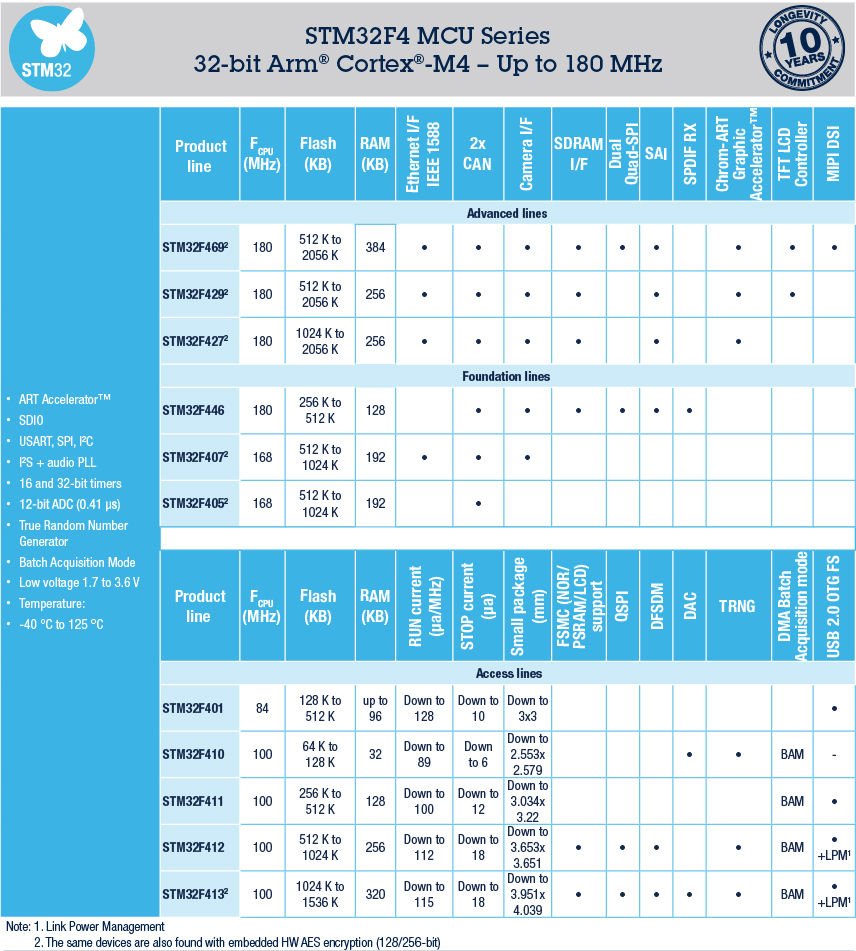
STM32F4 series of high-performance MCUs with DSP and FPU instructions
The ARM® Cortex®-M4-based STM32F4 MCU series leverages ST’s NVM technology and ART Accelerator™ to reach the industry’s highest benchmark scores for Cortex-M-based microcontrollers with up to 225 DMIPS/608 CoreMark executing from Flash memory at up to 180 MHz operating frequency.
With dynamic power scaling, the current consumption running from Flash ranges from 89 µA/MHz on the STM32F410 up to 260 µA/MHz on the STM32F439.
The STM32F4 series consists of eight compatible product lines of digital signal controllers (DSC), a perfect symbiosis of the real-time control capabilities of an MCU, and the signal processing performance of a digital signal processor (DSP):
- Advanced lines:
- 180 MHz CPU/225 DMIPS, up to 2 Mbytes of dual-bank Flash memory with SDRAM and Chrom-ART Accelerator™
- STM32F469/479 – Quad-SPI interface, LCD-TFT controller and MPI-DSI interface
- STM32F429/439 – LCD-TFT controller
- STM32F427/437 – serial audio interface, more performance and lower static power consumption
- 180 MHz CPU/225 DMIPS, up to 2 Mbytes of dual-bank Flash memory with SDRAM and Chrom-ART Accelerator™
- Foundation lines:
- STM32F446 – 180 MHz/225 DMIPS, up to 512 Kbytes of Flash memory with dual Quad-SPI and SDRAM interfaces
- STM32F407/417 – 168 MHz CPU/210 DMIPS, up to 1 Mbyte of Flash memory adding Ethernet MAC and camera interface
- STM32F405/415 – 168 MHz CPU/210 DMIPS, up to 1 Mbyte of Flash memory with advanced connectivity and encryption
- Access lines: The entry-level microcontrollers of the STM32F4 series!
- 84 MHz CPU/105 DMIPS, the smallest, cost-effective solution with outstanding power efficiency (Dynamic Efficiency™)
- STM32F401 – Less than 3 x 3mm with USB 2.0FS OTG and SDIO interfaces
- 100 MHz CPU/125 DMIPS, outstanding power efficiency (Dynamic Efficiency™) and Batch Acquisition Mode (BAM), a new smart DMA-optimizing power consumption for data batching
- STM32F410 – New milestone in outstanding power efficiency (89 µA/MHz and 6 µA in Stop mode), true random number generator, low-power timer, and DAC.
- STM32F411 – High RAM density and enhanced peripheral set such as USB 2.0FS OTG and up to 5 SPI interfaces.
- STM32F412 – High RAM and Flash memory density, USB interface, and enhanced peripheral set including a flexible external static memory controller with up to 16-bit data bus for LCD and external memory control, dual-mode Quad-SPI, CAN, DFSDM, and TRNG.
- STM32F413/F423 – Extends STM32F412 features with higher RAM and Flash memory density and an enhanced peripheral set including 10 UARTs, 3 CANs, SAI interface, a low-power timer, 2 DACs, 2 DFSDM with up to 6 filters. The STM32F423 includes AES encryption.
- 84 MHz CPU/105 DMIPS, the smallest, cost-effective solution with outstanding power efficiency (Dynamic Efficiency™)
Pinouts
The F401 model is one of the most popular, also considering the very affordable cost.
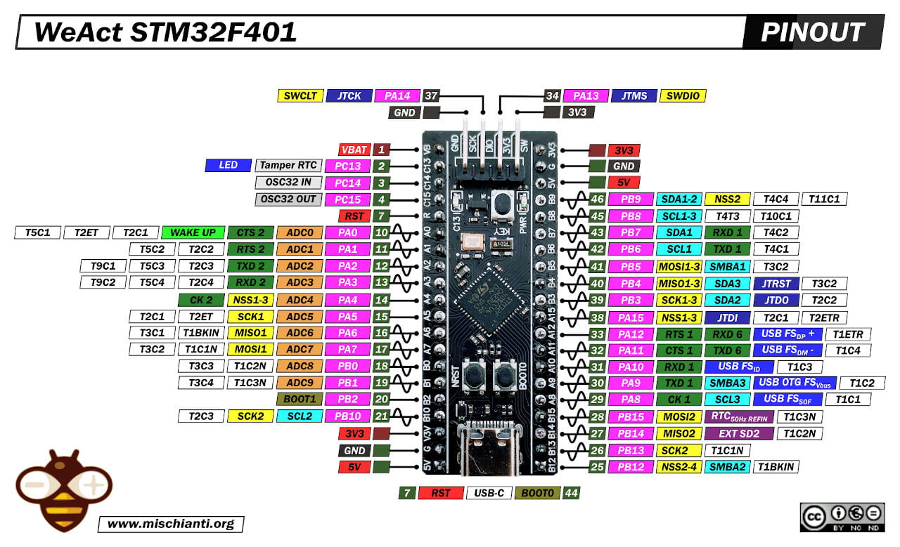
WeAct STM32F401CCU6 Black-Pill: high-resolution pinout and specs
The 411 version is certainly more performing, which also has an extra SPI, timer and I2S.
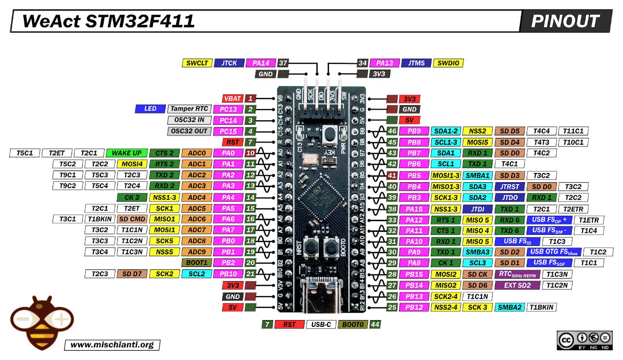
It is important to note pins 10 and 41 that F411 is not tolerant to 5V (check the red color of the square).
WeAct STM32F411CEU6 Black-Pill: high-resolution pinout and specs
But the 5V tolerance is one of the most important features of these F4xx series.
Arduino STM32 from STMicroelectronics
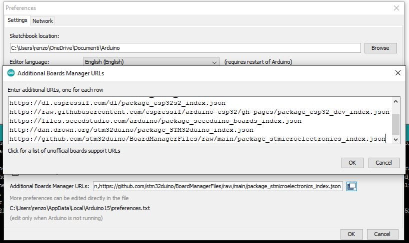
We must add the URL descriptor to our Arduino IDE.
https://github.com/stm32duino/BoardManagerFiles/raw/main/package_stmicroelectronics_index.json
Go to File –> Preferences and add the URL on “Additional Boards Manager URLs.”
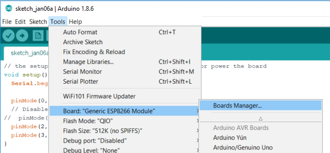
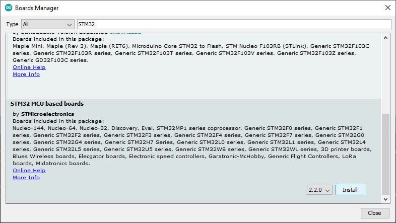
Then you must add a new board to Boards Manager
The boards to select are STM32 MCU-based boards.
Now you can choose the specified device:
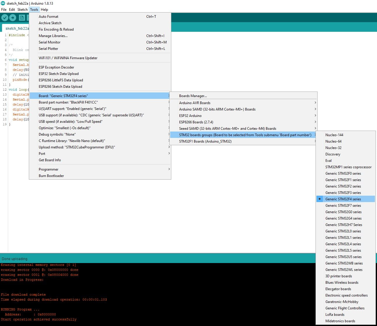
Now we are going to select the specified board.
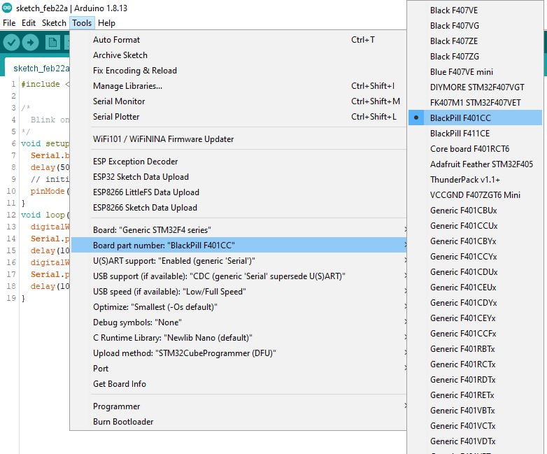
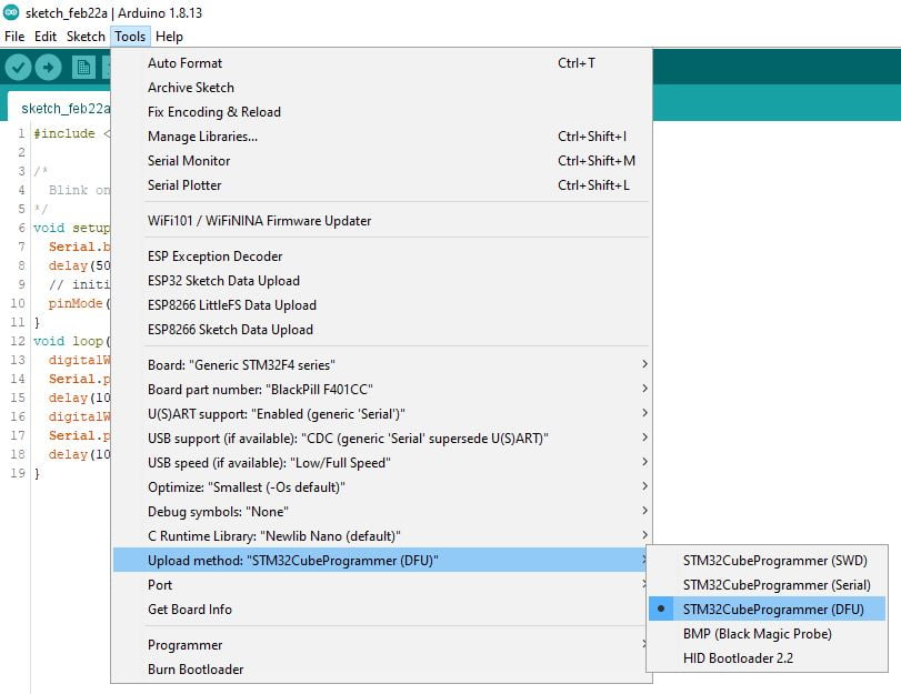
As already said, these devices have a DFU bootloader already uploaded, so you can use USB to program, and you must select the DFU bootloader.
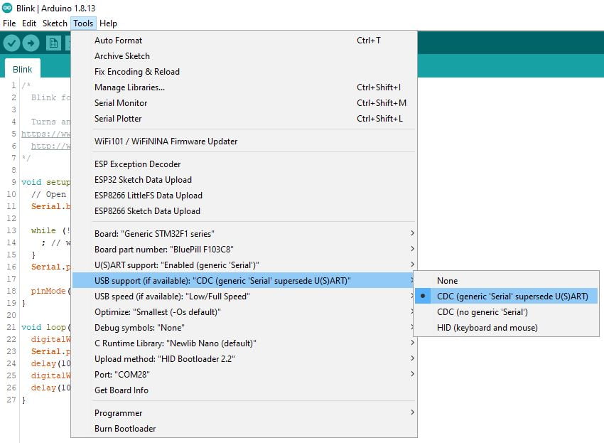
To use Serial to debug your code, you must select "USB support (if It's available): "CDC (generic 'Serial' supersede U(S)ART)"
Install STM32CubeProgrammer
To work, you also need to install the STM32CubeProgrammer released from STMicroelectronics.
You can download It from here.
Select boot mode
Put this device in boot mode:
- hold down BOOT0 button;
- push NRST button;
- release NRST;
- release BOOT0.
Now you have the red PWR led only.
Simple Blink sketch for STM32F4
My device has an LED on PA13.
/*
  Blink for STM32F4

  Turns an LED on for one second, then off for one second, repeatedly.

  http://www.mischianti.org
*/

void setup() {
  // Open serial communications and wait for port to open:
  Serial.begin(115200);

//  while (!Serial) {
//    ; // wait for serial port to connect. Needed for native USB port only
//  }
  Serial.println(F("Serial OK!"));

  pinMode(PC13, OUTPUT);
}

void loop() {
  digitalWrite(PC13, HIGH);
  Serial.println(F("HIGH!"));
  delay(1000);
  digitalWrite(PC13, LOW);
  Serial.println(F("LOW!"));
  delay(1000);
}
Now start the upload.
      -------------------------------------------------------------------
                       STM32CubeProgrammer v2.9.0
      -------------------------------------------------------------------


USB speed   : Full Speed (12MBit/s)
Manuf. ID   : STMicroelectronics
Product ID  : STM32  BOOTLOADER
SN          : 31A035713237
FW version  : 0x011a
Board       : --
Device ID   : 0x0433
Device name : STM32F401xD/E
Flash size  : 8 MBytes (default)
Device type : MCU
Revision ID : --
Device CPU  : Cortex-M4


Memory Programming ...
Opening and parsing file: sketch_feb22a.ino.bin
  File          : sketch_feb22a.ino.bin
  Size          : 24296 Bytes
  Address       : 0x08000000


Erasing memory corresponding to segment 0:
Erasing internal memory sectors [0 1]
erasing sector 0000 @: 0x08000000 done
erasing sector 0001 @: 0x08004000 done
Download in Progress:


File download complete
Time elapsed during download operation: 00:00:01.101

RUNNING Program ...
  Address:      : 0x8000000
Start operation achieved successfully
If all It’s ok, your C13 LED starts to blink, and as if by magic new Serial port has appeared, for me COM12.
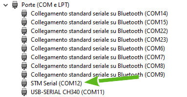
When connecting the serial monitor to the COM port, you get this result:
Serial OK!
HIGH!
LOW!
HIGH!
LOW!
HIGH!
LOW!
HIGH!
LOW!
HIGH!
Thanks
- STM32F1 Blue-Pill: pinout, specs, and Arduino IDE configuration (STM32duino and STMicroelectronics)
- STM32: program (STM32F1) via USB with STM32duino bootloader
- STM32: programming (STM32F1 STM32F4) via USB with HID boot-loader
- STM32F4 Black-Pill: pinout, specs, and Arduino IDE configuration
- STM32: ethernet w5500 with plain HTTP and SSL (HTTPS)
- STM32: ethernet enc28j60 with plain HTTP and SSL (HTTPS)
- STM32: WiFiNINA with ESP32 WiFi Co-Processor
- How to use SD card with stm32 and SdFat library
- \STM32: SPI flash memory FAT FS
- STM32: internal RTC, clock, and battery backup (VBAT)
- STM32 LoRa
- STM32 Power saving
- STM32F1 Blue-Pill clock and frequency management
- STM32F4 Black-Pill clock and frequency management
- Intro and Arduino vs STM framework
- Library LowPower, wiring, and Idle (STM Sleep) mode
- Sleep, deep sleep, shutdown, and power consumption
- Wake up from RTC alarm and Serial
- Wake up from the external source
- Backup domain intro and variable preservation across reset
- RTC backup register and SRAM preservation
- STM32 send emails with attachments and SSL (like Gmail): w5500, enc28j60, SD, and SPI Fash
- FTP server on STM32 with w5500, enc28j60, SD Card, and SPI Flash


Hi Renzo,
thank you very, very ! , much for this excellent description. You have saved me many lost hours, after I did not get the required support from my local german supplier. This guide line is perfect ! Yes my blue light is blinking and I can see the speed of the CPU is much higher that of ESP8266 or ESP32 or Arduino Nano, Uno, Mega. If you are interested to see the comparison, just send me an email as I have made the test already and will include the results in a PDF.
Hi Jos,
thanks, yes, I’d like to see It.
I am sending an email to you.
Bye Renzo
hi sir, can you send me blackpill bootloader…i cannot blinky the led like your step
Hi gibran,
you can find to the end of the article all the link to flash and download the firmware.
Bye Renzo
Thank you very much for creating an excellent introduction to using STM32F4xx boards with Arduino IDE. The serial USB example worked first time for me.
I have one question; I am trying to use hardware serial UARTs (1,2, and 6 on the STM32F411 pin out). In addition to your Serial USB example, I have found that Serial1 works on TXD1/RXD1 (PA9/PA10) but I get errors when trying to use Serial2 or higher (like on Arduino ATMEGA2560).
Is there some configuration necessary for STM32?
Hi Andy,
if I understand you must declare the Hardware Serial like so
HardwareSerial Serial2(USART2);
or
HardWareSerial Serial2 (PA3, PA2);
Bye Renzo
Hi Renzo,
Thank you for your reply.
Your suggested solution: “HardwareSerial Serial2(USART2);” works perfectly! I now see serial TX on PA2 and RX on PA3.
I look forward to experimenting with STM32 Blackpill.
Grazie mille!
Hi Andy,
Sure, keep us posted on your progress.
Bye Renzo
I am currently work on project with a custom STM32f411ceu6 chip. I would to upload the sketch from raspberry pi terminal without using Arduino IDE. I have installed all the required from this source: Site
TX (pin 8) — RX (pin A10); RX (pin 10) –TX (pin A9).
When I am running the command$ stm32flash -v -w led.ino.Generic_F411Cx.bin /dev/serial0.
The uploading is successful but the led isnot flashing connected to PIn 12 of the board. Any suggestion will be welcome.
Hi Sevic,
I never use a secondary micro controller as serial adapter, but pay attention to the jumper setting, if you select the boot position you risk to override the boot-loader and the sketch doesn’t start.
Bye Renzo
Hi Renzo,
Thanks for your excellent work! I am new to stm32 boards , follow your guide I successfully flashing the test code and the led blinks as expected. But the serial monitor didn’t print anything, anything wrong? BTW, I am using a stm32f401 board.
Eric
Thanks Lu,
Check the UsART parameter on Arduino ide.
Bye Renzo
I got problems connecting the ST-LINK v2 with the STM32F401CC, It was working perfectly till I burnt a code included PIN8 to PIN12 in PORTA as an output,
I was trying the code by the OCD, but after this I couldn’t reconnect the MCU with the PC again even with “STM32 ST-LINK utility” program. it gives me
** Can not connect to target!
Please select “Connect Under Reset” mode from Target->Settings menu and try again.
If you’re trying to connect to a low frequency application , please select a lower SWD Frequency mode from Target->Settings menu.
**
and when I try again it gives me
**
STLink USB communication error
**
Is there any way to clear the Flash memory by hardware ?
Hi Ariad,
try to use Visual Studio Code that simplify a lot this process and you can’t make errors.
Bye Renzo
I am trying to follow your instructions for programming a STM32F401CCU6 Black Pill. In particular, I need a better understanding of the different roles played by the ST-LINK V2, the Arduino IDE, the STM32CubeProgrammer and the Black Pill’s USB-C connector..
The setup of the Arduino IDE is clearly to facilitate a functioning communications interface between the computer and a STM32F401CCU6 Black Pill.
Setting the “Upload method” to “STM32CubeProgrammer (DFU)” leads me to assume the programming is done through the ST-LINK V2
Hence, “To work, you also need to install the STM32CubeProgrammer”.
By this stage, the ST-LINK V2 needs to be connected to the STM32F401CCU6 Black Pill using ST-LINK V2 pins SWDIO (2), GND (4), SWCLK (6), and 3.3V (8), and the ST-LINK V2 USB A connector needs to be plugged into a USB port on the computer.
When the Black Pill is correctly connected to the ST-LINK V2, and the ST-LINK V2 is plugged into a USB Port on the computer, the STM32CuebProgrammer can be run. “ST-LINK” should be selected as the interface mode on the Memory and File editing screen. The “ST-LINK configuration” panel shows the configuration parameters, e.g.Serial number, Port, etc.. However, at the same time, it’s indicated as being “Not connected” (next to a red dot at the top of the screen).
I don’t understand why STM32CubeProgrammer is displaying the ST-LINK configuration parameters and, at the same time, is “Not connected”.
I conclude that it is not necessary to power the STM32F401CCU6 Black Pill via the USB C connector. There is no mention of it in the text (ref. part 4), and, in any case, 3.3V is already being supplied from pin 8 of the ST-LINK V2.
With all that said, I still have this feeling that the STM32F401CCU6 Black Pill can also be programmed via the USB C interface, so I am left scratching my head!
Hi Howard,
you are right, if you use ST-LINK you don’t need to power via USB, but USB is very usefully to the serial monitor for debugging (if you don’t use ST-LINK to debug via odb).
You can use only USB for programming by upload a specified bootloader like described here.
STM32: programming (STM32F1 STM32F4) via USB with HID boot-loader – 3
Bye Renzo
Thanks for your reply, Renzo.
You have given me an unfamiliar topic worthy of further research, i.e. using “ST-LINK to debug via odb”. No doubt I will have to get my head around debugging sooner rather than later.
I’ve just figured out that STM32CubeProgrammer will only recognise the ST-LINK V2 USB dongle when the STM32CubeProgrammer ST-LINK configuration settings are as follows:
Port: SWD (default)
Frequency: 4000 (default)
Mode: Under reset (default)
Access Port: 0 (default)
Reset mode: Hardware reset (default)
Speed: Reliable (default)
Shared: Enabled
Debug in low power mode: not ticked*
* Leaving this checkbox ticked results in a warning: “Debug in low power mode is not supported”, so I un-ticked that checkbox.
After clicking the refresh icon, to the right of the the Serial number drop down box, the ST-LINK Serial number is now displayed! (The critical change was to the Shared parameter — it has to be enabled).
So, I can now use the ST-LINK V2 USB dongle to connect the STM32F401CCU6 Black Pill to the computer while running STM32CubeProgrammer.
But where does that get me? I’m writing code for the Black Pill in the Arduino IDE, and the IDE is configured according to your this tutorial, i.e. “Black Pill STM32F4: pinout, specs, and Arduino IDE configuration – 4”, whereby I end up with the following IDE parameters in the Tools menu:
Board; “Generic STM32F4 series”
Debug symbols and core logs: “None”
Optimize: “Smallest (-Os default)”
Board part number: “BlackPill F401CC”.
C Runtime Library: “Newlib Nano (default)”
Upload method: “STM32CubeProgrammer (DFU)”
USB support (if available): “CDC (generic ‘Serial” supersede U(S)ART)”
U(S)ART support: “Enabled (generic ‘Serial’)”
USB speed (if available): “Low/Full Speed”
So it seems to me that I’ve abandoned the STM32CubeProgrammer (with ST-LINK) workflow in favor of the Arduino IDE (with USB) workflow. But then, under the heading “Install STM32CubeProgrammer”, you say: “To work, you also need to install the STM32CubeProgrammer released from STMicroelectronics”.
Then, under the heading “Select boot mode”, you say:
“Put this device in boot mode:
– hold down BOOT0 button;
– push NRST button;
– release NRST;
– release BOOT0.
Now you have the red PWR led only.”
So, we’re now ready to “start the upload”, via USB (the ST-LINK V2 USB dongle should have been disconnected before the USB-A to USB-C cable was plugged into the Black Pill).
But I have to ask (naively) what is the reasoning behind putting the Black Pill into boot mode, using the BOOT0 and NRST buttons, if the Black Pill already has a preprogrammed bootloader in system memory?
Aren’t we trying to upload the compiled sketch code into flash memory?
Bye,
Tony
Hi Howard,
The STM32CubeProgrammer is needed only for the drivers and environment, after installing that, forget It.
The use of button to put on boot mode isn’t for install bootloader but to permit to the STM32 to receipt the sketch on the flash when you use the standard and preloaded DFU bootloader or if you use the SWT with ST-LINK.
Bye Renzo
Hi Renzo,
Thanks, again, for your help.
After configuring the Arduino IDE in accordance with your tutorial (4) instructions, I ran STM32CubeProgrammer (it was already installed) and then I closed it. So, just like you said, I can now “forget it” (hopefully)!
Up to this point, my poor STM32F401CCU6 Black pill is just an inanimate object, not plugged into any other hardware — it’s not connect to the computer, either via a ST-LINK V2 USB dongle, or a USB-A to USB-C cable. So the next step is to connect it to the computer via a USB-A to USB-C cable.
I must have done this before, and the Black Pill must have been recognized as a valid USB device, because I was able to upload a sketch. But that is not the case now.
Although the Black Pill is powered up, and the previously uploaded Blink Sketch is running, it’s not being recognised as a connected USB device in Device Manager. And it’s not being recognised by the Arduino IDE when I attempt to upload a sketch.
Try to put on boot mode and check if now is visible, if not you don’t have a correct bootloader.
So you must use ST-LINK to upload the HID bootloader if you want to use only the USB.
Else you can continue to use ST-LINK to program and USB to debug (by configure the parameter correctly on your Arduino IDE).
Bye Renzo
Thanks, Renzo. I now remember what I did the last time I got the Black Pill’s USB connection working.
I think it was a March 2020 hobbycomponents.com forum post (https://forum.hobbycomponents.com/viewtopic.php?t=2946) that nailed it.
In answer to the following FAQ (which is more of a statement really):
“When in normal mode the module works fine but when entering bootloader DFU mode the device comes up as a “Unknown USB device (Device Descriptor Request Failed)”.”
They wrote:
“Correct operation of DFU mode is reliant on the STM32 IC to be close to ambient room temperature (~25 deg. C). When entering DFU mode the STM32 executes its internal bootloader firmware. For USB communication the bootloader firmware needs to use the external crystal oscillator (HSE) for correct USB timing. Because the firmware does not have prior knowledge of the frequency of the external oscillator it must first calculate it. This is done by using the STM32’s intal RC oscillator (HSI, MSI) to calculate the frequency of the external crystal. However, the internal RC oscillator is sensitive to ambient temperature and if the device is too warm or too cold it can cause the internal oscillator to operate outside of its 1% tolerance and in turn cause and incorrect calculation of the external oscillator frequency. This results in incorrect USB timing causing the above error.”
“Note that this does not affect the device in normal running mode as the correct external crystal frequency is programmed into the users application.”
“If you are experiencing this issue and the device may be in an environment where it could be too hot or too cold, try entering DFU mode again when the device is at a temperature closer to 25 deg. C. For example, if the device is too cold try warming it slightly with your finger.”
In support of this novel solution, they reference ST application note AN2606, which is currently up to Rev 60, and is located at:
https://www.st.com/content/ccc/resource/technical/document/application_note/b9/9b/16/3a/12/1e/40/0c/CD00167594.pdf/files/CD00167594.pdf/jcr:content/translations/en.CD00167594.pdf
They go on to say: “Also see section 3.1 page 21 … for more information”, however that reference is out of date. AN2606 Rev 60 contains an update to the quoted text, which is now in a note appended to Table 2. “Bootloader activation patterns” in section 4.1, on pages 31 and 32″, as follows:
“Note: For STM32 devices embedding bootloader using the DFU/CAN interface in which the external clock source (HSE) is required for DFU/CAN operations, the detection of the HSE value is done dynamically by the bootloader firmware and is based on the internal oscillator clock (HSI, MSI). When (because of temperature variations or other conditions) the internal oscillator precision is altered above the tolerance band (1% around the theoretical value), the bootloader might calculate a wrong HSE frequency value. In this case, the bootloader DFU/CAN interfaces might malfunction or not work at all.”
So, all I had to do was apply a moderate source of heat to the STM32F4 chip while putting the Black Pill into boot mode.
The Black Pill now appears as “STM32 BOOTLOADER” under Universal Serial Bus devices in Windows 10 Device Manager.