STM32 power saving: RTC backup register and SRAM preservation – 9

Finally, we look at the backup domain to resolve the problem of state preservation across sleep modes, first the RTC backup registry and then the backup of SRAM memory.
Check which kind of backup is available on STM32
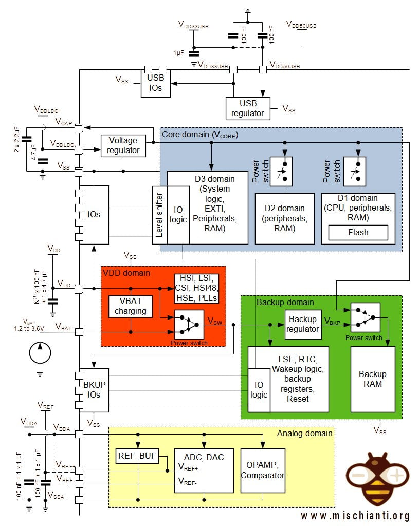
To preserve the state in shutdown/standby you can use (as described in the introduction) RTC/TAMP register or SRAM.
Here the STM32 and ST-Link V2 used in this test STM32F103C8T6 STM32F401 STM32F411 ST-Link v2 ST-Link v2 official
Here the FTDI USB to TTL CH340G - USB to TTL FT232RL
Here my multimeter Aneng SZ18
Here is a simple sketch to verify your STM32.
/**
 * A simple sketch to check witch kind of backup you can use
 * on your device
 *
 * Renzo Mischianti <www.mischianti.org>
 * en: https://mischianti.org/category/tutorial/stm32-tutorial/
 * it: https://mischianti.org/it/category/guide/guida-alla-linea-di-microcontrollori-stm32/
 *
 */

#include "STM32LowPower.h"

void printBackupRegisterType();
void printSRAMAvailability();

void setup()
{
  Serial.begin(115200);
  delay(1000);

  Serial.println(F("------------------------------------------------"));
  printBackupRegisterType();
  printSRAMAvailability();
  Serial.println(F("------------------------------------------------"));

}

void loop()
{
  delay(1000);
}

void printBackupRegisterType() {
#if defined(BKP_BASE)
	Serial.println(F("Backup base enabled!"));
#elif defined(RTC_BKP0R)
	Serial.println(F("Backup RTC enabled!"));
#elif defined(TAMP_BKP0R)
#if defined(STM32G4xx) || defined(STM32L5xx) || defined(STM32U5xx) ||\
    defined(STM32MP1xx) || defined(STM32WLxx)
  /* For those series this API requires RTC even if it is not used
     and TAMP is used instead */
	Serial.println(F("Backup RTC and TAMP enabled! TAMP busy use RTC!"));
#else
	Serial.println(F("Backup RTC and TAMP enabled! Use TAMP!"));
#endif
#else
	Serial.println(F("Backup not available!"));
#endif

}

void printSRAMAvailability() {
#if defined(BKPSRAM_BASE)
	Serial.println(F("SRAM available!"));
#else
	Serial.println(F("SRAM not available!"));
#endif
}
In my case with an STM32F401 I get this result :(.
------------------------------------------------
Backup RTC enabled!
SRAM not available!
------------------------------------------------
So I can use only the RTC register, but I try to give you an SRAM example.
Using a backup register to preserve data across shutdown/standby
Now we are going to add the data in the data structure under the backup area. As described you can use (if present) RTC Backup Register or SRAM; check the paragraph with the sketch to verify which one your microcontroller has.
/**
 * A simple sketch that set the time to
 * 2022-04-20 at 16:00:00 and an alarm at 16:00:10
 * the result is the interrupt after 10 secs
 * We use RTC backup register to preserve state of a variable
 * across the shutdown and count the restart
 * The valiable is resetted every time you disconnect the power.
 *
 * Renzo Mischianti <www.mischianti.org>
 * https://mischianti.org
 *
 */

#include "STM32LowPower.h"
#include <STM32RTC.h>

/* Get the rtc object */
STM32RTC& rtc = STM32RTC::getInstance();

/* Change these values to set the current initial time */
const byte seconds = 0;
const byte minutes = 0;
const byte hours = 16;

/* Change these values to set the current initial date */
const byte day = 20;
const byte month = 4;
const byte year = 22;

void alarmMatch(void *data);
void printWakeSource();
void printBackupRegisterType();
void printClockReady();

void setup()
{
  Serial.begin(115200);

  Serial.println(F("------------------------------------------------"));
  printWakeSource();
  printBackupRegisterType();
  printClockReady();
  Serial.println(F("------------------------------------------------"));

  // Initialize the variable only on first power-on reset
  if (__HAL_RCC_GET_FLAG(RCC_FLAG_BORRST)) {
	  enableBackupDomain();
	  resetBackupDomain();

	  setBackupRegister(LL_RTC_BKP_DR0, 0);
  }
  __HAL_RCC_CLEAR_RESET_FLAGS();

  // Select RTC clock source: LSI_CLOCK, LSE_CLOCK or HSE_CLOCK.
  // By default the LSI is selected as source.
//  rtc.setClockSource(STM32RTC::LSI_CLOCK);

  rtc.begin(); // initialize RTC 24H format
  // we set the time at 2022-04-20 at 16:00:00
  rtc.setTime(hours, minutes, seconds);
  rtc.setDate(day, month, year);

  delay(1000);


  String someRandomData = "www.mischianti.org";

  // Configure low power
  LowPower.begin();
  LowPower.enableWakeupFrom(&rtc, alarmMatch, &someRandomData);

  int wakeSeconds = rtc.getSeconds()+20;
  // Now we set an alert at 16:00:10
  // pratically 10 secs after the start
  // (check the initialization of clock)
  rtc.setAlarmDay(day);
  rtc.setAlarmTime(16, 0, wakeSeconds, 0);
  rtc.enableAlarm(rtc.MATCH_DHHMMSS);

  Serial.print("Boot number RTC backup register: ");
//  uint32_t boot_count_RTC_back = rtc_read_backup_reg(RTC_BKP_DR1);
  uint32_t boot_count_RTC_back = getBackupRegister(LL_RTC_BKP_DR0);
  Serial.println(boot_count_RTC_back);
  boot_count_RTC_back = boot_count_RTC_back + 1;
//  rtc_write_backup_reg(RTC_BKP_DR1, boot_count_RTC_back);
  setBackupRegister(LL_RTC_BKP_DR0, boot_count_RTC_back);

  Serial.println("Start shutdown mode in ");
  for (int i = 10;i>0;i--) { Serial.print(i); Serial.print(" "); delay(1000); } Serial.println( "OK!" );
  // Print date...
  Serial.printf("Now is %02d/%02d/%02d %02d:%02d:%02d.%03d and we set the wake at 16:10! So wait 10secs! \n",
		  rtc.getDay(), rtc.getMonth(), rtc.getYear(),
		  rtc.getHours(), rtc.getMinutes(), rtc.getSeconds(), rtc.getSubSeconds());
  delay(1000);

  LowPower.shutdown();
}

void loop()
{
  // Print date...
  Serial.printf("%02d/%02d/%02d ", rtc.getDay(), rtc.getMonth(), rtc.getYear());

  // ...and time
  Serial.printf("%02d:%02d:%02d.%03d\n", rtc.getHours(), rtc.getMinutes(), rtc.getSeconds(), rtc.getSubSeconds());
  delay(1000);
}

void alarmMatch(void *data)
{
	String myData = *(String*)data;
	Serial.println("Alarm Match!");
	Serial.println(myData);
}

void printClockReady() {
	if (__HAL_RCC_GET_FLAG(RCC_FLAG_HSIRDY)) {
	    Serial.println(F("HSI oscillator clock ready."));
	}
	if (__HAL_RCC_GET_FLAG(RCC_FLAG_HSERDY)) {
	    Serial.println(F("HSE oscillator clock ready."));
	}
	if (__HAL_RCC_GET_FLAG(RCC_FLAG_PLLRDY)) {
	    Serial.println(F("Main PLL clock ready."));
	}
	if (__HAL_RCC_GET_FLAG(RCC_FLAG_PLLI2SRDY)) {
	    Serial.println(F("PLLI2S clock ready."));
	}
	if (__HAL_RCC_GET_FLAG(RCC_FLAG_LSERDY)) {
	    Serial.println(F("LSE oscillator clock ready."));
	}
	if (__HAL_RCC_GET_FLAG(RCC_FLAG_LSIRDY)) {
	    Serial.println(F("LSI oscillator clock ready."));
	}
}

void printWakeSource() {
	Serial.println(F("-----------------------------------"));
	if (__HAL_RCC_GET_FLAG(RCC_FLAG_BORRST)) {
	    Serial.println(F("Wake from POR/PDR or BOR reset."));
	}
	if (__HAL_RCC_GET_FLAG(RCC_FLAG_PINRST)) {
	    Serial.println(F("Wake from Pin reset."));
	}
	if (__HAL_RCC_GET_FLAG(RCC_FLAG_PORRST)) {
	    Serial.println(F("Wake from POR/PDR reset."));
	}
	if (__HAL_RCC_GET_FLAG(RCC_FLAG_SFTRST)) {
	    Serial.println(F("Wake from Software reset."));
	}
	if (__HAL_RCC_GET_FLAG(RCC_FLAG_IWDGRST)) {
	    Serial.println(F("Wake from Independent Watchdog reset."));
	}
	if (__HAL_RCC_GET_FLAG(RCC_FLAG_WWDGRST)) {
	    Serial.println(F("Wake from Window Watchdog reset."));
	}
	if (__HAL_RCC_GET_FLAG(RCC_FLAG_LPWRRST)) {
	    Serial.println(F("Wake from Low Power reset."));
	}
	Serial.println(F("-----------------------------------"));
}

void printBackupRegisterType() {
#if defined(BKP_BASE)
	Serial.println(F("Backup base enabled!"));
#elif defined(RTC_BKP0R)
	Serial.println(F("Backup RTC enabled!"));
#elif defined(TAMP_BKP0R)
#if defined(STM32G4xx) || defined(STM32L5xx) || defined(STM32U5xx) ||\
    defined(STM32MP1xx) || defined(STM32WLxx)
  /* For those series this API requires RTC even if it is not used
     and TAMP is used instead */
	Serial.println(F("Backup RTC and TAMP enabled! TAMP busy use RTC!"));
#else
	Serial.println(F("Backup RTC and TAMP enabled! Use TAMP!"));
#endif
#else
	Serial.println(F("Backup not available!"));
#endif

}
You can see that we reset the variable every time we disconnect the device from the power.
  // Initialize the variable only on first power-on reset
  if (__HAL_RCC_GET_FLAG(RCC_FLAG_BORRST)) {
	  enableBackupDomain();
	  resetBackupDomain();

	  setBackupRegister(LL_RTC_BKP_DR0, 0);
  }
  __HAL_RCC_CLEAR_RESET_FLAGS();
When the device is reconnected to the power (__HAL_RCC_GET_FLAG(RCC_FLAG_BORRST)) we enable the backup (enableBackupDomain(); you can use disableBackupDomain(); to disable It) and initialize the variable to 0 (setBackupRegister(LL_RTC_BKP_DR0, 0);).
Then we read the data from the register, print data, add one to the variable and set It into the register.
  Serial.print("Boot number RTC backup register: ");
//  uint32_t boot_count_RTC_back = rtc_read_backup_reg(RTC_BKP_DR1);
  uint32_t boot_count_RTC_back = getBackupRegister(LL_RTC_BKP_DR0);
  Serial.println(boot_count_RTC_back);
  boot_count_RTC_back = boot_count_RTC_back + 1;
//  rtc_write_backup_reg(RTC_BKP_DR1, boot_count_RTC_back);
  setBackupRegister(LL_RTC_BKP_DR0, boot_count_RTC_back);
To get the value from the register we use uint32_t boot_count_RTC_back = getBackupRegister(LL_RTC_BKP_DR0);.
The serial output after the first power disconnect is:
------------------------------------------------
-----------------------------------
Wake from POR/PDR or BOR reset.
Wake from Pin reset.
Wake from POR/PDR reset.
-----------------------------------
Backup RTC enabled!
HSI oscillator clock ready.
HSE oscillator clock ready.
Main PLL clock ready.
------------------------------------------------
Boot number RTC backup register: 0
Start shutdown mode in
10 9 8 7 6 5 4 3 2 1 OK!
Now is 20/04/22 16:00:10.408 and we set the wake at 16:10! So wait 10secs!
------------------------------------------------
-----------------------------------
-----------------------------------
Backup RTC enabled!
HSI oscillator clock ready.
HSE oscillator clock ready.
Main PLL clock ready.
LSI oscillator clock ready.
------------------------------------------------
Boot number RTC backup register: 1
Start shutdown mode in
10 9 8 7 6 5 4 3 2 1 OK!
Now is 20/04/22 16:00:10.404 and we set the wake at 16:10! So wait 10secs!
------------------------------------------------
-----------------------------------
-----------------------------------
Backup RTC enabled!
HSI oscillator clock ready.
HSE oscillator clock ready.
Main PLL clock ready.
LSI oscillator clock ready.
------------------------------------------------
Boot number RTC backup register: 2
Start shutdown mode in
10 9 8 7 6 5 4 3 2 1 OK!
Now is 20/04/22 16:00:10.388 and we set the wake at 16:10! So wait 10secs!
------------------------------------------------
-----------------------------------
-----------------------------------
Backup RTC enabled!
HSI oscillator clock ready.
HSE oscillator clock ready.
Main PLL clock ready.
LSI oscillator clock ready.
------------------------------------------------
Boot number RTC backup register: 3
Start shutdown mode in
10 9 8 7 6 5 4 3 2 1 OK!
Now is 20/04/22 16:00:10.400 and we set the wake at 16:10! So wait 10secs!
Using SRAM memory to preserve data across shutdown/standby
As already described I don’t have a device that supports SRAM, so I try to do an example only with documentation without a test.
/**
 * A simple sketch that set the time to
 * 2022-04-20 at 16:00:00 and an alarm at 16:00:10
 * the result is the interrupt after 10 secs
 * We use SRAM to preserve state of a structure
 * across the shutdown and count the restart
 * The structure is resetted every time you disconnect the power.
 *
 * Renzo Mischianti <www.mischianti.org>
 * https://mischianti.org
 *
 */

#include "STM32LowPower.h"
#include <STM32RTC.h>

/* Get the rtc object */
STM32RTC& rtc = STM32RTC::getInstance();

/* Change these values to set the current initial time */
const byte seconds = 0;
const byte minutes = 0;
const byte hours = 16;

/* Change these values to set the current initial date */
const byte day = 20;
const byte month = 4;
const byte year = 22;

void alarmMatch(void *data);
void printWakeSource();
void printSRAMAvailability();

typedef struct Info
  {
  char url[19];                           // Change
  int deviceID;
  int count;
  };

void setup()
{
  Serial.begin(115200);

  Serial.println(F("------------------------------------------------"));
  printWakeSource();
  printSRAMAvailability();
  Serial.println(F("------------------------------------------------"));

  // Initialize the variable only on first power-on reset
  if (__HAL_RCC_GET_FLAG(RCC_FLAG_BORRST)) {
	  enableBackupDomain();
	  resetBackupDomain();

	  struct Info info = {"www.mischianti.org", 1, 0};
	  writeBackupSRAM(0, (uint32_t*)&info, sizeof(info));

  }
  __HAL_RCC_CLEAR_RESET_FLAGS();

  // Select RTC clock source: LSI_CLOCK, LSE_CLOCK or HSE_CLOCK.
  // By default the LSI is selected as source.
//  rtc.setClockSource(STM32RTC::LSI_CLOCK);

  rtc.begin(); // initialize RTC 24H format
  // we set the time at 2022-04-20 at 16:00:00
  rtc.setTime(hours, minutes, seconds);
  rtc.setDate(day, month, year);

  delay(1000);


  String someRandomData = "www.mischianti.org";

  // Configure low power
  LowPower.begin();
  LowPower.enableWakeupFrom(&rtc, alarmMatch, &someRandomData);

  int wakeSeconds = rtc.getSeconds()+20;
  // Now we set an alert at 16:00:10
  // pratically 10 secs after the start
  // (check the initialization of clock)
  rtc.setAlarmDay(day);
  rtc.setAlarmTime(16, 0, wakeSeconds, 0);
  rtc.enableAlarm(rtc.MATCH_DHHMMSS);

  Serial.print("Boot number SRAM: ");
  struct Info info;
  readBackupSRAM(0, (uint32_t*)&info, sizeof(info));
  Serial.println(info.count);
  info.count = info.count + 1;
  writeBackupSRAM(0, (uint32_t*)&info, sizeof(info));

  Serial.println("Start shutdown mode in ");
  for (int i = 10;i>0;i--) { Serial.print(i); Serial.print(" "); delay(1000); } Serial.println( "OK!" );
  // Print date...
  Serial.printf("Now is %02d/%02d/%02d %02d:%02d:%02d.%03d and we set the wake at 16:10! So wait 10secs! \n",
		  rtc.getDay(), rtc.getMonth(), rtc.getYear(),
		  rtc.getHours(), rtc.getMinutes(), rtc.getSeconds(), rtc.getSubSeconds());
  delay(1000);

  LowPower.shutdown();
}

void loop()
{
  // Print date...
  Serial.printf("%02d/%02d/%02d ", rtc.getDay(), rtc.getMonth(), rtc.getYear());

  // ...and time
  Serial.printf("%02d:%02d:%02d.%03d\n", rtc.getHours(), rtc.getMinutes(), rtc.getSeconds(), rtc.getSubSeconds());
  delay(1000);
}

void alarmMatch(void *data)
{
	String myData = *(String*)data;
	Serial.println("Alarm Match!");
	Serial.println(myData);
}

void printWakeSource() {
	Serial.println(F("-----------------------------------"));
	if (__HAL_RCC_GET_FLAG(RCC_FLAG_BORRST)) {
	    Serial.println(F("Wake from POR/PDR or BOR reset."));
	}
	if (__HAL_RCC_GET_FLAG(RCC_FLAG_PINRST)) {
	    Serial.println(F("Wake from Pin reset."));
	}
	if (__HAL_RCC_GET_FLAG(RCC_FLAG_PORRST)) {
	    Serial.println(F("Wake from POR/PDR reset."));
	}
	if (__HAL_RCC_GET_FLAG(RCC_FLAG_SFTRST)) {
	    Serial.println(F("Wake from Software reset."));
	}
	if (__HAL_RCC_GET_FLAG(RCC_FLAG_IWDGRST)) {
	    Serial.println(F("Wake from Independent Watchdog reset."));
	}
	if (__HAL_RCC_GET_FLAG(RCC_FLAG_WWDGRST)) {
	    Serial.println(F("Wake from Window Watchdog reset."));
	}
	if (__HAL_RCC_GET_FLAG(RCC_FLAG_LPWRRST)) {
	    Serial.println(F("Wake from Low Power reset."));
	}
	Serial.println(F("-----------------------------------"));
}

void printSRAMAvailability() {
#if defined(BKPSRAM_BASE)
	Serial.println(F("SRAM available!"));
#else
	Serial.println(F("SRAM not available!"));
#endif
}
Thanks
- STM32F1 Blue-Pill: pinout, specs, and Arduino IDE configuration (STM32duino and STMicroelectronics)
- STM32: program (STM32F1) via USB with STM32duino bootloader
- STM32: programming (STM32F1 STM32F4) via USB with HID boot-loader
- STM32F4 Black-Pill: pinout, specs, and Arduino IDE configuration
- STM32: ethernet w5500 with plain HTTP and SSL (HTTPS)
- STM32: ethernet enc28j60 with plain HTTP and SSL (HTTPS)
- STM32: WiFiNINA with ESP32 WiFi Co-Processor
- How to use SD card with stm32 and SdFat library
- \STM32: SPI flash memory FAT FS
- STM32: internal RTC, clock, and battery backup (VBAT)
- STM32 LoRa
- STM32 Power saving
- STM32F1 Blue-Pill clock and frequency management
- STM32F4 Black-Pill clock and frequency management
- Intro and Arduino vs STM framework
- Library LowPower, wiring, and Idle (STM Sleep) mode
- Sleep, deep sleep, shutdown, and power consumption
- Wake up from RTC alarm and Serial
- Wake up from the external source
- Backup domain intro and variable preservation across reset
- RTC backup register and SRAM preservation
- STM32 send emails with attachments and SSL (like Gmail): w5500, enc28j60, SD, and SPI Fash
- FTP server on STM32 with w5500, enc28j60, SD Card, and SPI Flash
- Connecting the EByte E70 to STM32 (black/blue pill) devices and a simple sketch example