
STM32: programming (STM32F1 STM32F4) via USB with HID boot-loader – 3
We continue exploring the STM32 family of 32-bit microcontrollers based on the Arm® Cortex®-M processor.
We’ll learn how to add HID bootloader to our STM32 device. This bootloader does not need drivers (no USB drivers needed, even on Windows) for STM32F10x and STM32F4xx devices.
This turns out to be a small 2 KB bootloader on STM32F10x devices. On STM32F4xx devices, there is no point to make the bootloader much smaller than 16 KB because the first flash page is already 16 KB.
First of all, read the previous article “STM32F1: pinout, specs, and Arduino IDE configuration (STM32duino and STMicroelectronics)” where you can find out how to configure your Arduino IDE, and pay attention: this bootloader want the Arduino_STM of STMicroelectronics URL descriptor (second part of the previous article).
Here the most commons STM32 STM32F103C8T6 STM32F401 STM32F411 ST-Link v2 ST-Link v2 official
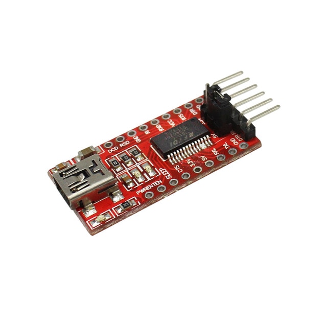
As already described, you need an FTDI programmer. I usually use a basic model, but in this case, It’s more simple to use a module with integrated power output.
The more expensive FT232RL or FT232 module can power the microcontroller, but a CH340G or CH340 works well.
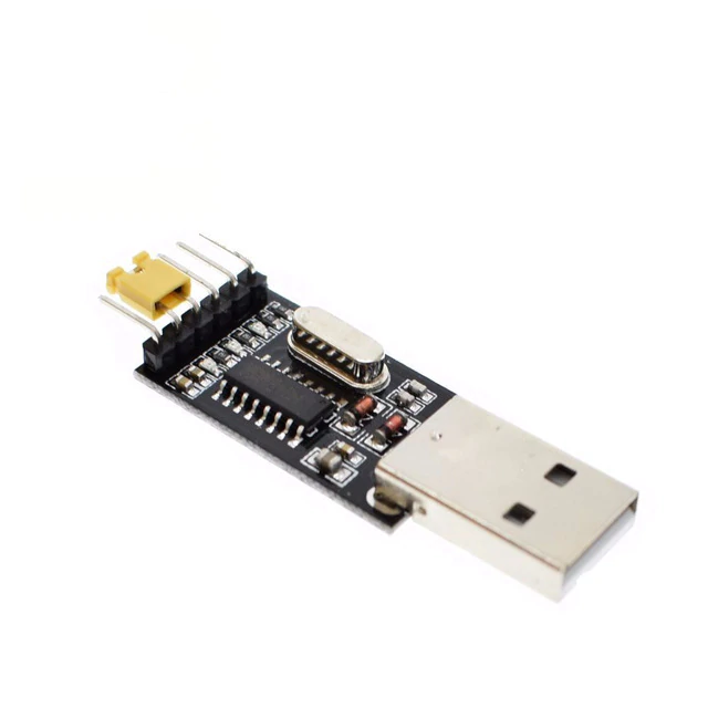
Here the two model USB to TTL CH340G - USB to TTL FT232RL
Connection schema with FTDI
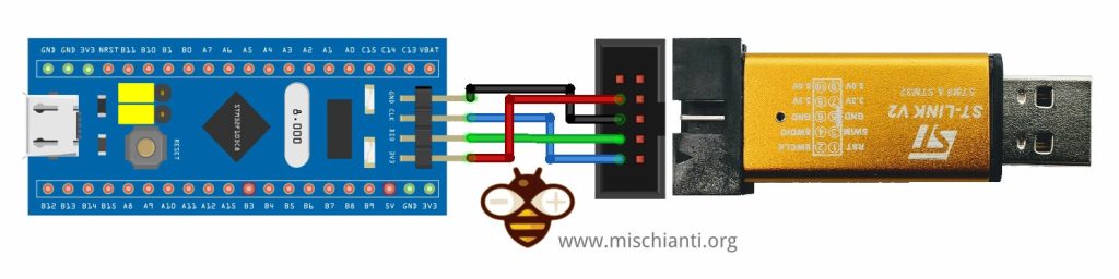
To upload the bootloader, you need to connect the FTDI, as explained in this image.
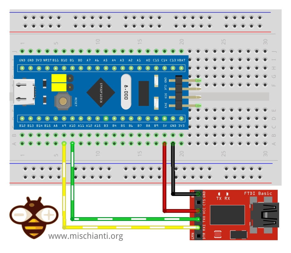
You can power the stm32 with 3.3v or 5v in the respective pin, and you must connect FTDI TX to PA10 and RX to PA9.
| STM32F103C8T6 | FTDI |
|---|---|
| 5v or 3.3v | VCC 5v or 3.3v |
| GND | GND |
| A9 | RX |
| A10 | TX |
Connection schema with ST-Link
| STM32 | ST-Link v2 |
|---|---|
| GND | GND |
| SCK | SWCLK |
| DIO | SWDIO |
| 3V3 | 3V3 |
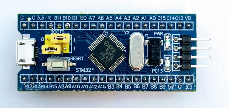
Boot modalities

You can select three types of boot mode:
- Boot from System Memory: that invokes the on-chip bootloader, which is present in the chip directly from the factory before you’ve programmed anything into the on-chip flash. This allows you to load (program) code into the device from an external interface such as UART or USB.
- Main flash memory: is where your code typically goes. In normal operation, your code will reside in flash, and on Power-On Reset (POR), the CPU will fetch the reset vector and initial stack pointer (SP) from flash. You can load flash via JTAG, the on-chip bootloader (above), etc.
- Load code into RAM (JTAG, runtime) and then boot/run from there. This isn’t often used, usually, you’re doing something tricky like a temporary bootloader or the like.
Here is the table with jumper configuration:
| BOOT0 | BOOT1 | Modality |
|---|---|---|
| 0 | X | Main flash memory |
| 1 | 0 | System Memory |
| 1 | 1 | Embedded SRAM |
Upload HID bootloader with STM32CubeProgrammer
To upload the bootloader, we must put the device in “System Memory”.
We need the new STM32CubeProgrammer already installed (needed from Arduino IDE), and we will try some bootloader.
You can find that firmware at this GitHub repository
https://github.com/Serasidis/STM32_HID_Bootloader
But you must download the precompiled one from this link. In the package, you can find the firmware for F103 and F104, and for F103, you must select high density for High-Density Devices such as STM32F103RCT6 or low-medium density for the others.
You must select the firmware low/medium density hid_generic_pc13.bin, the pc13. It’s the LED pin in my case, PA13.
Connect the FDTI as shown.
Set the jumper in Boot mode “System memory” and reset.
- Install the STM32CubeProgrammer released from STMicroelectronics. You can download It from here;
- Download the precompiled firmware from this link, I had explain how to select the firmware up.
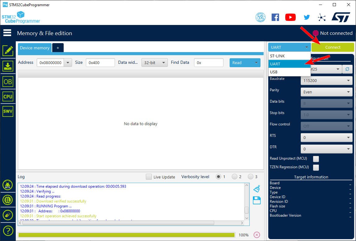
- Start the program;
- Select UART connection type;
- Select the correct COM port;
- Click Connect;
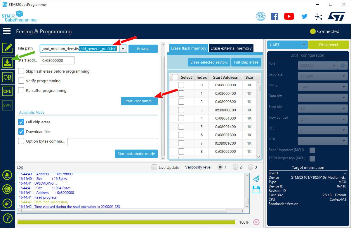
- Click on Erase & Programming icon (green arrow);
- Select the correct STM32duino bootloader (as described previous);
- Start programming, your device is ready.
After the upload, you must set the jumper in normal mode and reset it.
If all was going ok, the PC13 led start blinking very fast, but you can’t see any new device in your COM ports (only unknown device in USB). But don’t worry.
Upload the Blink sketch
Now we will upload the sketch for the first time, you may have some problems the first time and I will try to explain how to fix them.
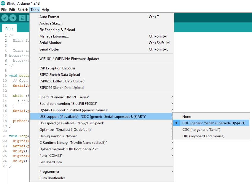
Select "USB support (if It's available): "CDC (generic 'Serial' supersede U(S)ART)"
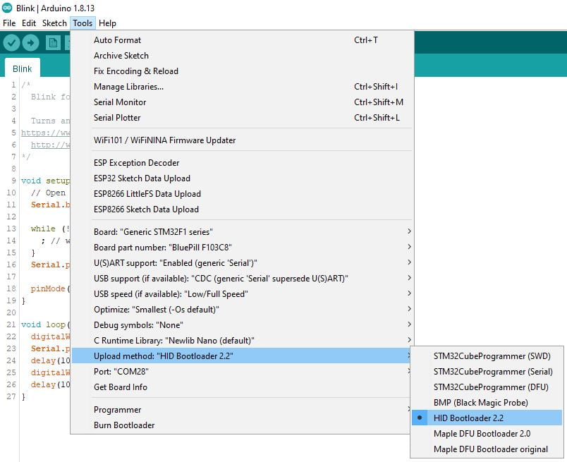
And "Upload method": "HID bootloader 2.2"
Here is the blink sketch; look at the Serial management; the sketch start working after Serial is connected.
/*
  Blink for STM32F1xx

  Turns an LED on for one second, then off for one second, repeatedly.

  http://www.mischianti.org
*/

void setup() {
  // Open serial communications and wait for port to open:
  Serial.begin(115200);

  while (!Serial) {
    ; // wait for serial port to connect. Needed for native USB port only
  }
  Serial.print(F("Serial OK!"));

  pinMode(PC13, OUTPUT);
}

void loop() {
  digitalWrite(PC13, HIGH);
  delay(1000);
  digitalWrite(PC13, LOW);
  delay(1000);
}
You must connect the Serial monitor to start the sketch.
Try to upload if you get an error message like this.
C:\Users\renzo\AppData\Local\Arduino15\packages\STMicroelectronics\tools\STM32Tools\2.1.1/win/hid-flash.exe C:\Users\renzo\AppData\Local\Temp\arduino_build_278975/Blink.ino.bin COM28

+-----------------------------------------------------------------------+
|         HID-Flash v2.2.1 - STM32 HID Bootloader Flash Tool            |
|     (c)      2018 - Bruno Freitas       http://www.brunofreitas.com   |
|     (c) 2018-2019 - Vassilis Serasidis  https://www.serasidis.gr      |
|   Customized for STM32duino ecosystem   https://www.stm32duino.com    |
+-----------------------------------------------------------------------+

> Trying to open the [COM28]...
> Unable to open the [COM28]
> Searching for [1209:BEBA] device...
##########
Error - [1209:BEBA] device is not found :(> Searching for [COM28] ...
> Finish
the selected serial port > Finish
 does not exist or your board is not connected
Disconnect and reconnect and retry, if the upload freeze like so
C:\Users\renzo\AppData\Local\Arduino15\packages\STMicroelectronics\tools\STM32Tools\2.1.1/win/hid-flash.exe C:\Users\renzo\AppData\Local\Temp\arduino_build_278975/Blink.ino.bin COM28

+-----------------------------------------------------------------------+
|         HID-Flash v2.2.1 - STM32 HID Bootloader Flash Tool            |
|     (c)      2018 - Bruno Freitas       http://www.brunofreitas.com   |
|     (c) 2018-2019 - Vassilis Serasidis  https://www.serasidis.gr      |
|   Customized for STM32duino ecosystem   https://www.stm32duino.com    |
+-----------------------------------------------------------------------+

> Trying to open the [COM28]...
> Unable to open the [COM28]
> Searching for [1209:BEBA] device...
#
> [1209:BEBA] device is found !
> Sending <reset pages> command...
> Flashing firmware...
. 1024 Bytes
Reset and retry again, and now you get the upload.
An error occurred while uploading the sketch
C:\Users\renzo\AppData\Local\Arduino15\packages\STMicroelectronics\tools\STM32Tools\2.1.1/win/hid-flash.exe C:\Users\renzo\AppData\Local\Temp\arduino_build_278975/Blink.ino.bin COM28

+-----------------------------------------------------------------------+
|         HID-Flash v2.2.1 - STM32 HID Bootloader Flash Tool            |
|     (c)      2018 - Bruno Freitas       http://www.brunofreitas.com   |
|     (c) 2018-2019 - Vassilis Serasidis  https://www.serasidis.gr      |
|   Customized for STM32duino ecosystem   https://www.stm32duino.com    |
+-----------------------------------------------------------------------+

> Trying to open the [COM28]...
> Unable to open the [COM28]
> Searching for [1209:BEBA] device...
#
> [1209:BEBA] device is found !
> Sending <reset pages> command...
> Flashing firmware...
. 1024 Bytes
. 2048 Bytes
. 3072 Bytes
. 4096 Bytes
. 5120 Bytes
. 6144 Bytes
. 7168 Bytes
. 8192 Bytes
. 9216 Bytes
. 10240 Bytes
. 11264 Bytes
. 12288 Bytes
. 13312 Bytes
. 14336 Bytes
. 15360 Bytes
. 16384 Bytes
. 17408 Bytes
. 18432 Bytes
. 19456 Bytes
. 20480 Bytes
. 21504 Bytes
. 22528 Bytes
. 23552 Bytes
. 24576 Bytes

> Done!
> Sending <reboot mcu> command...
> Error while sending <reboot mcu> command.
> Searching for [COM28] ...
> [COM28] is found !
> Finish
And finally, you have the COM port named “STM Serial”. You must connect the Serial monitor. After that, the led starts to blink, and you have this Serial output.
Serial OK!
Troubleshooting
If your device does not go in bootloader mode, you can get the COM port by moving the jumper BOOT 1 in the HIGH position (1) and reset.
Thanks
- STM32F1 Blue-Pill: pinout, specs, and Arduino IDE configuration (STM32duino and STMicroelectronics)
- STM32: program (STM32F1) via USB with STM32duino bootloader
- STM32: programming (STM32F1 STM32F4) via USB with HID boot-loader
- STM32F4 Black-Pill: pinout, specs, and Arduino IDE configuration
- STM32: ethernet w5500 with plain HTTP and SSL (HTTPS)
- STM32: ethernet enc28j60 with plain HTTP and SSL (HTTPS)
- STM32: WiFiNINA with ESP32 WiFi Co-Processor
- How to use SD card with stm32 and SdFat library
- \STM32: SPI flash memory FAT FS
- STM32: internal RTC, clock, and battery backup (VBAT)
- STM32 LoRa
- STM32 Power saving
- STM32F1 Blue-Pill clock and frequency management
- STM32F4 Black-Pill clock and frequency management
- Intro and Arduino vs STM framework
- Library LowPower, wiring, and Idle (STM Sleep) mode
- Sleep, deep sleep, shutdown, and power consumption
- Wake up from RTC alarm and Serial
- Wake up from the external source
- Backup domain intro and variable preservation across reset
- RTC backup register and SRAM preservation
- STM32 send emails with attachments and SSL (like Gmail): w5500, enc28j60, SD, and SPI Fash
- FTP server on STM32 with w5500, enc28j60, SD Card, and SPI Flash
- Connecting the EByte E70 to STM32 (black/blue pill) devices and a simple sketch example


I am not able to see a COM port in device manager. The device descriptor request failed shows up in device manager.
Hi Vibhore,
Please open a forum topic with the detail of the problem.
Bye Renzo