esp-12 esp-07 (esp8266) programming board and breadboard adapter
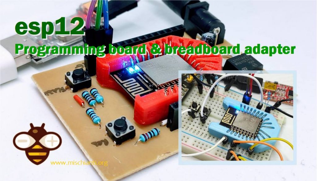
When I went to use esp12 and esp07, and the first problem was how to put it on the breadboard, luckily I found an adapter developed by tweeto, and that was what I needed, but I would like to make it easier to use, so I redesigned it smaller and added some labels to identify the pins.
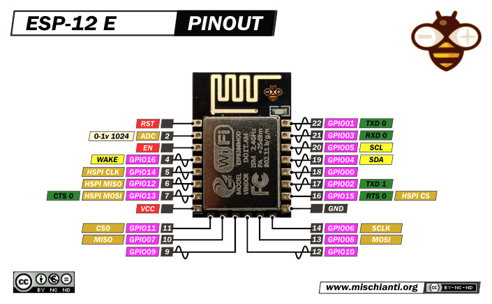
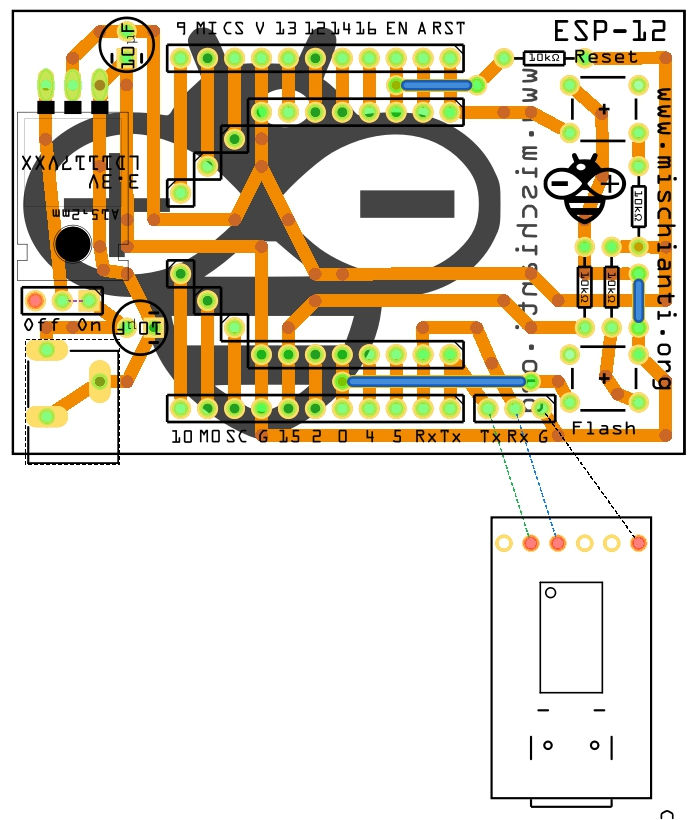
esp12 E pinout hight resolution
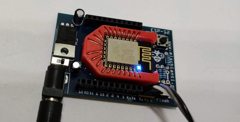
3d printed breadboard adapter
Here the stl to print.
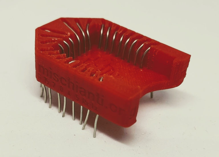
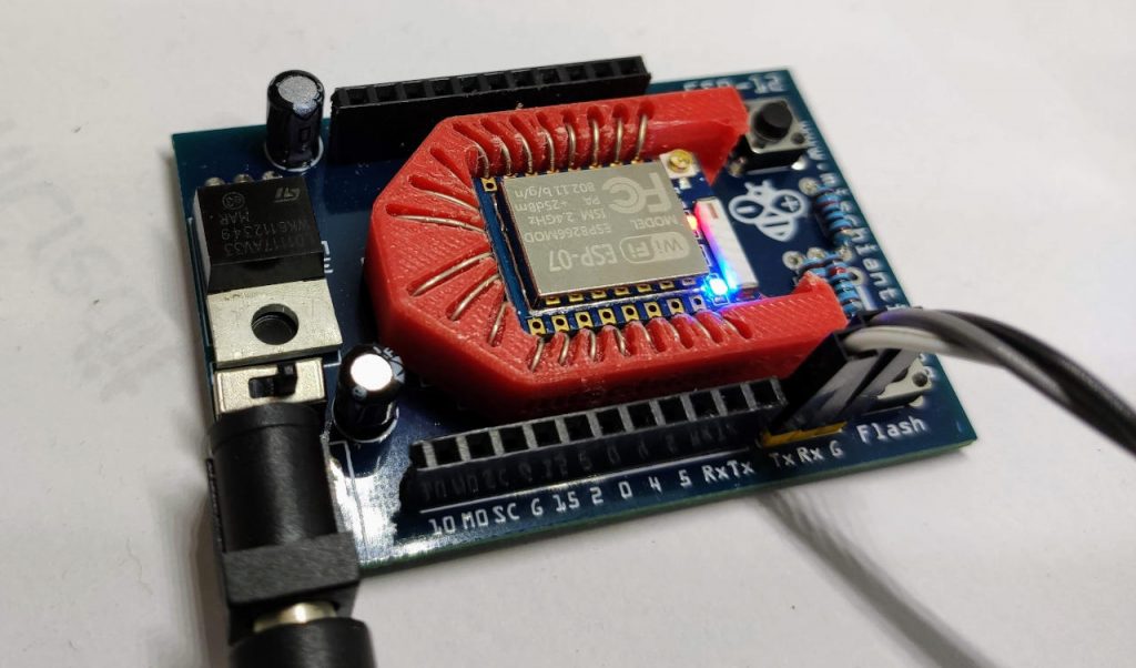
Socket for esp12 and esp07 with V base
Now you must add the wires, I use a telephone wire that is a single copper wire with 0.6mm (I think 0.8mm can fit better) of diameter, and I’m going to insert in the adapter (the wire in question does not have good conductivity on the outside, preferably completely made of copper).
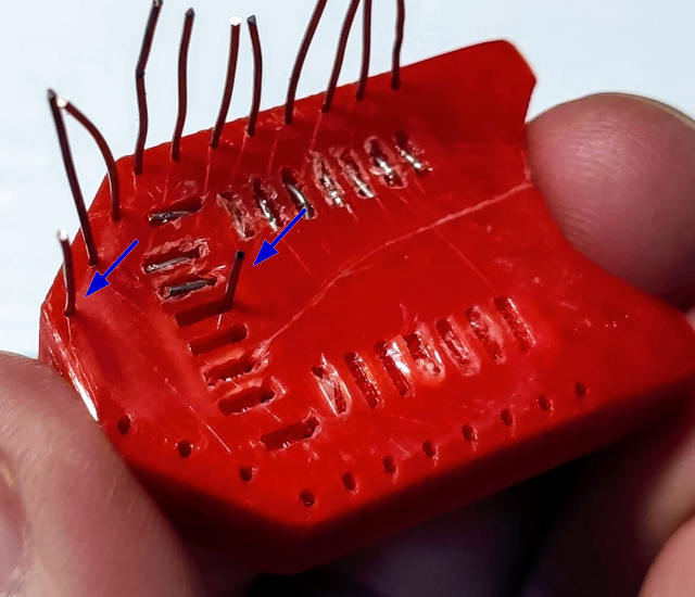
Insert it into the innermost holes and push it out about 3mm
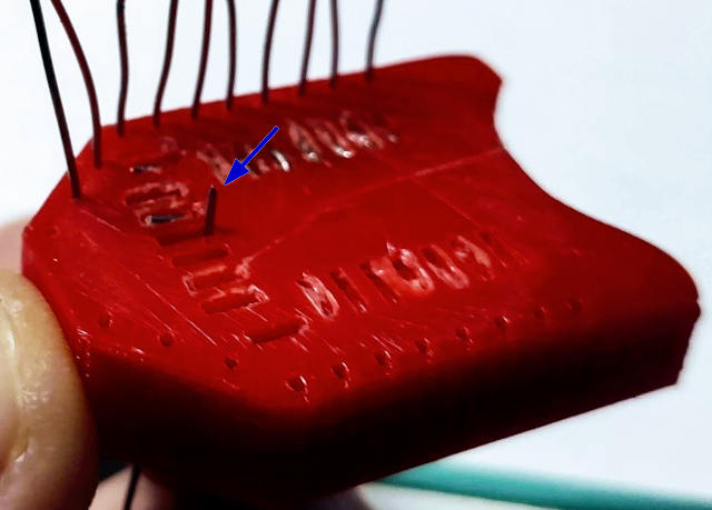
Bend the wire to the external of the adapter.
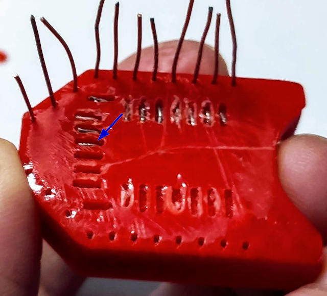
Cut external part of the wire, and extract,
then reinsert in the internal and external hole.
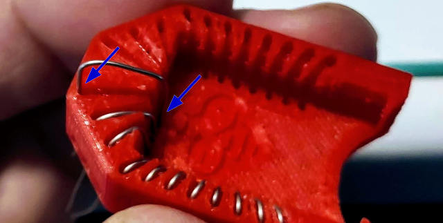
Now check if you need to cut more the wire of the internal hole, and bend It.
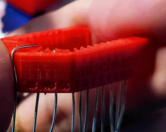
Repeat for all pins.
Now you can use It directly on the breadboard.
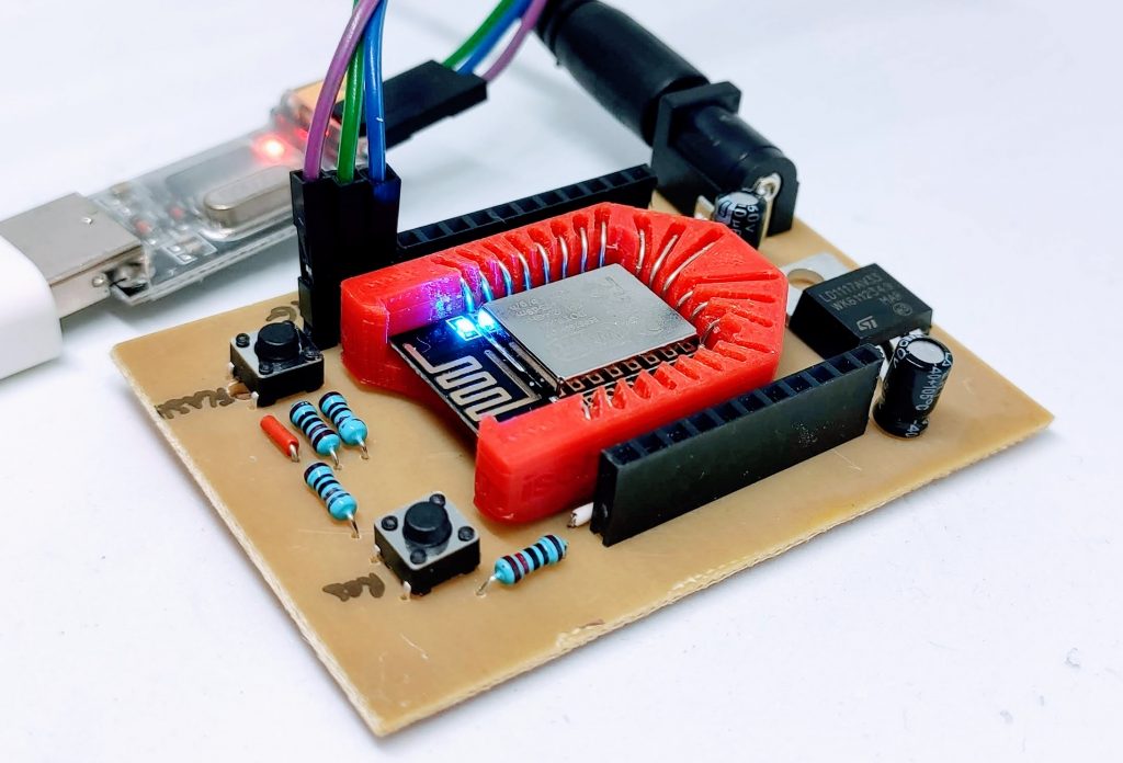
Programming board PCB
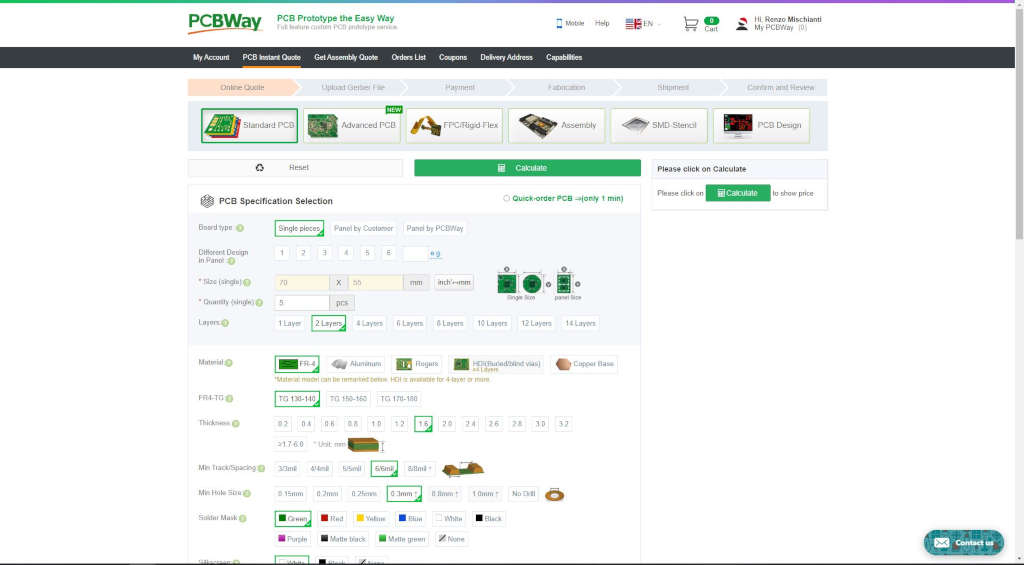
You can get my PCB without additional costs at PCBWay PCBWay

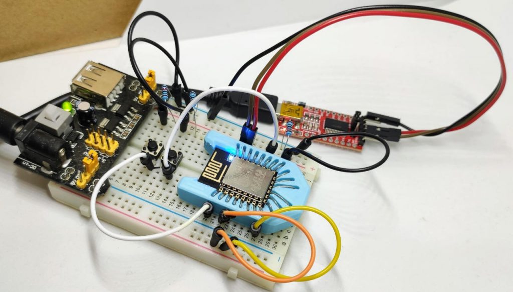
The next step is to do a PCB instead the breadboard to program the device, I’m going to use the adapter only to create/test new circuit.
Here the list of component:
Shopping List
| Amount | Part Type | Properties |
|---|---|---|
| 2 | Electrolytic Capacitor | package 100 mil [THT, electrolytic]; capacitance 10µF |
| 1 | FTDI Basic Programmer | voltage 3.3V; tipo Basic |
| 1 | ESP 12E | pins 22; chip label 8266; variant 12E; editable pin labels false |
| 2 | Pushbutton | package [THT] |
| 1 | Power Jack | tipo 5.5mm barrel breadboard friendly |
| 2 | Generic female header – 11 pins | package THT; form ♀ (female) |
| 6 | Generic female header – 1 pins | hole size 1.0mm,0.508mm; pins 1; row single; pin spacing 0.1in (2.54mm); package THT; form ♀ (female) |
| 1 | Toggle Switch | switching circuit SPDT; package THT |
| 4 | 10kΩ Resistor | pin spacing 400 mil; resistenza 10kΩ; package THT |
| 1 | Generic male header – 3 pins | package THT; form ♂ (male) |
| 1 | LD1117V33 | voltage 3.3V; package 78xxl; chip LD1117VXX |
Here some material more difficult to find:
esp-12 esp-07 Aliexpress esp-12 - Aliexpress esp-07
Barrel jack Aliexpress Breadboard friendly 5.5x2.1 - Aliexpress 5.5x2.1
Voltage regulator AliExpress SMD (AMS1117) - AliExpress 3.3v (LM1117) - AliExpress 5v (7805) - AliExpress 9v (7809)AliExpress 12v (7812) - AliExpress 3.3v TO-92 (78L33)
Here the FTDI USB to TTL CH340G - USB to TTL FT232RL
Based on the tutorial “esp12 esp07 (esp8266): programming, pinout, specs and IDE configuration” I create a PCB.
You can get pcb without additional costs here from PCBWay
I chose this manufacturer because at the same cost it offers excellent quality, in the first screen it is possible to make countless options suitable for every need.
The board as you can see on various photo is very beautiful and simply to solder.
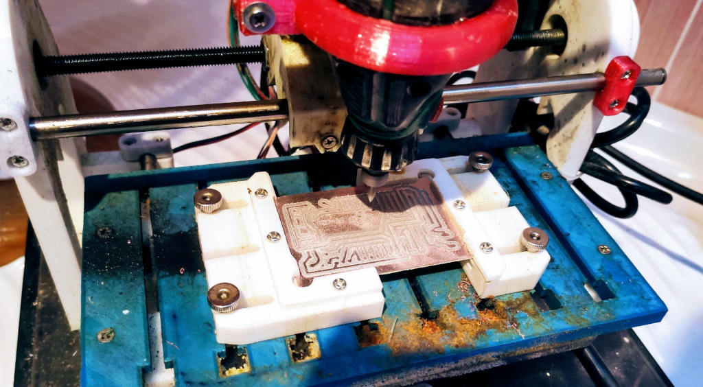
The PCB is fully tested with my standardized process. First the milling process as you can see in the tutorial (with my CNC):
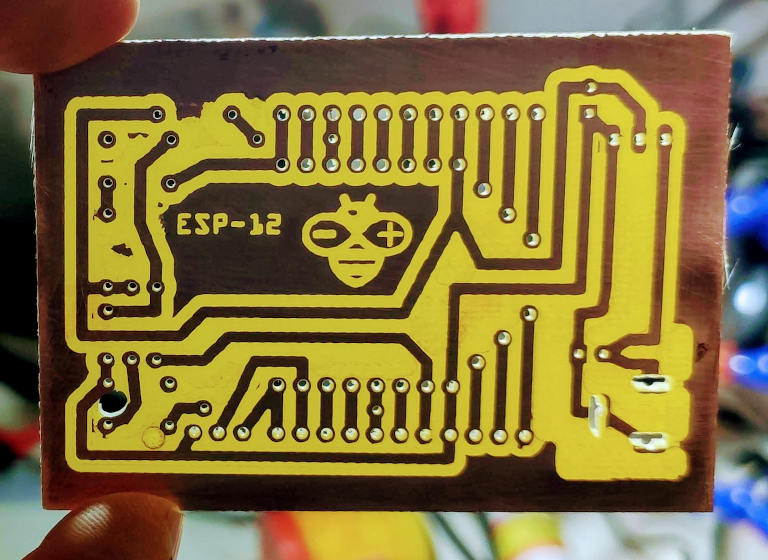
Here the milled PCB:
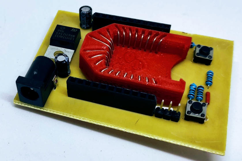
And here after assembly process:
Now we can upload the code, check the tutorial “esp12 esp07 (esp8266): programming, pinout, specs and IDE configuration“.