
GY-291 ADXL345 i2c spi accelerometer with interrupt for esp32, esp8266, stm32 and Arduino
An accelerometer is a tool that measures proper acceleration. Proper acceleration is the acceleration (the rate of change of velocity) of a body in its own instantaneous rest frame; this is different from coordinate acceleration, which is acceleration in a fixed coordinate system.
The ADXL345 is a small, thin, ultralow power, 3-axis accelerometer with high resolution (13-bit) measurement at up to ±16 g. Digital output data is formatted as 16-bit twos complement and is accessible through either an SPI (3- or 4-wire) or I2C digital interface.

The ADXL345 is well suited for mobile device applications. It measures the static acceleration of gravity in tilt-sensing applications, as well as dynamic acceleration resulting from motion or shock. Its high resolution (3.9 mg/LSB) enables the measurement of inclination changes less than 1.0°.
This module support 3.3v and 5v power supply, but It hasn’t a logic level converter and needs a 3.3v connection for long-time communication.
How does an accelerometer work
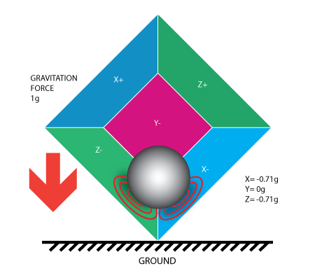
An accelerometer works on the principle of piezoelectric effect. Here, imagine a cuboidal box, having a small ball inside it, like in the picture below:
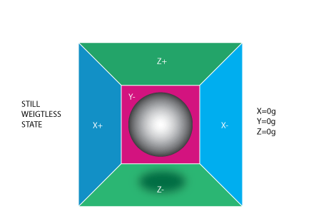
The walls of this box are made with piezoelectric crystals. Whenever you tilt the box, the ball is forced to move in the direction of the inclination,
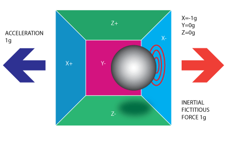
due to gravity. The wall with which the ball collides creates tiny piezo electric currents. There are totally, three pairs of opposite walls in a cuboid. Each pair corresponds to an axis in 3D space: X, Y, and Z axes.
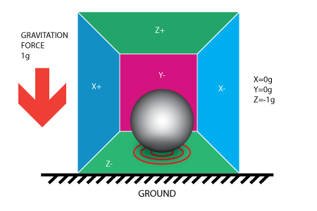
Depending on the current produced from the piezoelectric walls, we can determine the direction of inclination and its magnitude.
Each accelerometer has a zero-g voltage level, you can find it in the specification of the accelerometer, also have a sensitivity, usually expressed in mV/g, divide the zero-g level corrected reading by the sensitivity to produce the final reading proof mass deflection is measured as a change in capacitance between the proof mass and sensing platesInternal circuitry converts the tiny capacitance to a voltage signal which is digitized and output.
With this characteristic, the accelerometer can also be used to correct magnetometer errors.
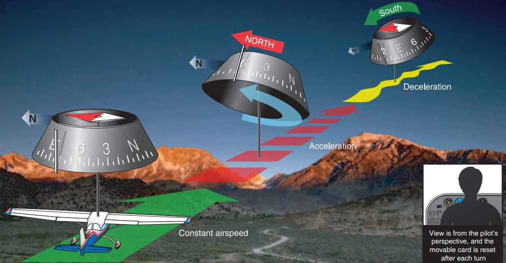
You can get more information in the flying manual.
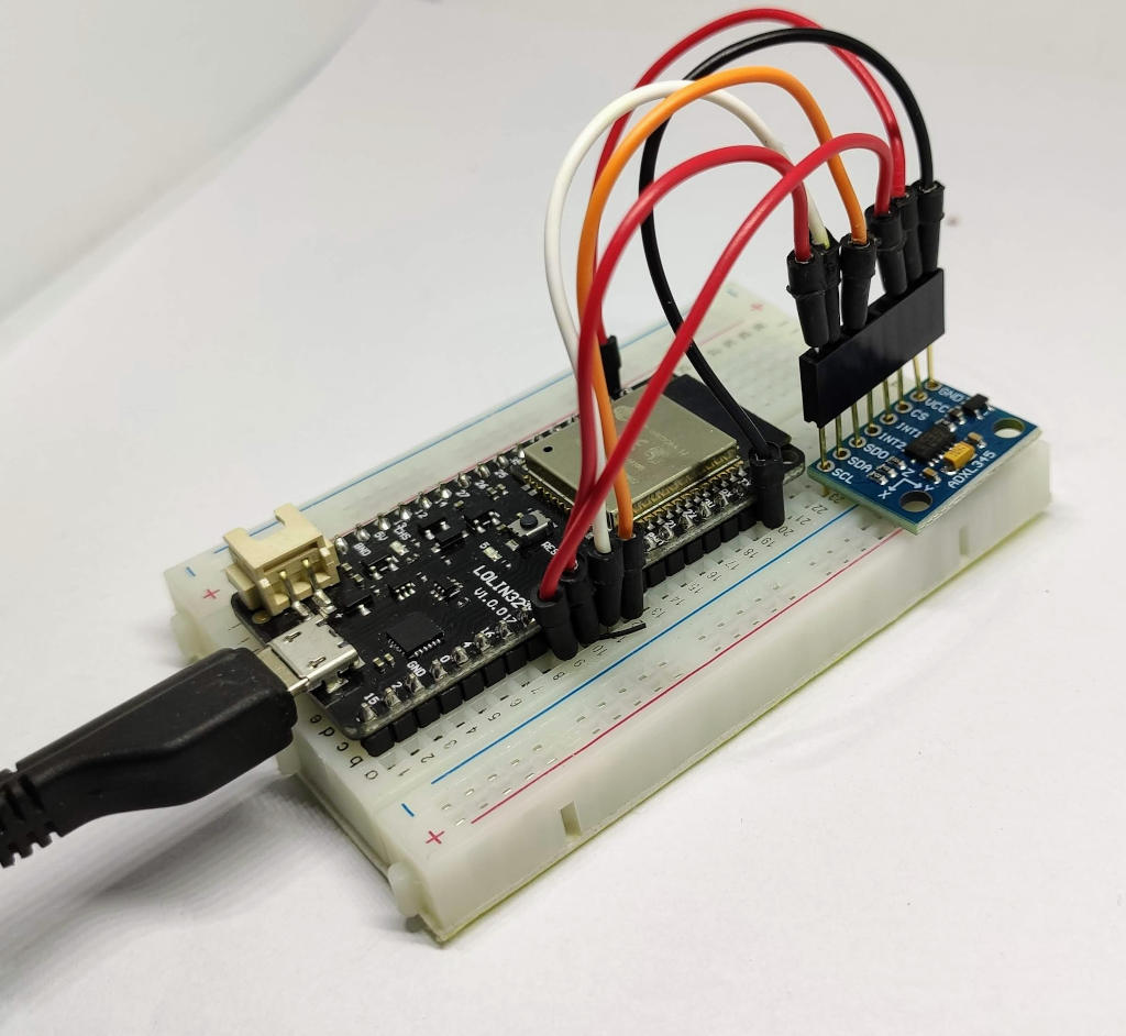
Wiring
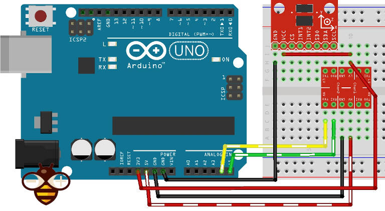
Arduino i2c connection
For Arduino UNO, It’s better if you don’t connect directly to A4 and A5 pin because the logic voltage is 5v, and the module support 3.3v only (limit 3.6v), It works well without also, but you risk burning It.
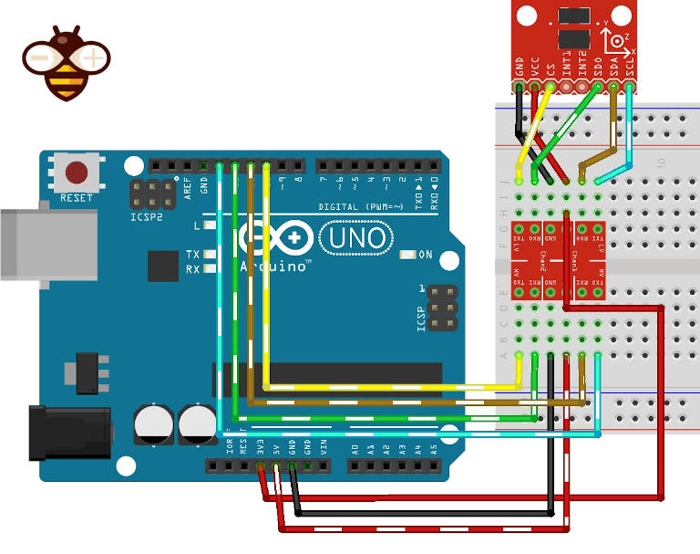
Arduino SPI connection
Spi is more difficult to connect, but It’s grants more speed.
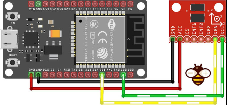
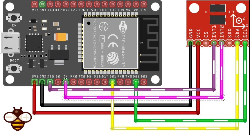
esp32 i2c connection
The esp8266 and esp32 have a 3.3v logic, so they work without problems.
esp32 with i2c connection on standard pin SDA and SCL GPIO21 and GPIO22.
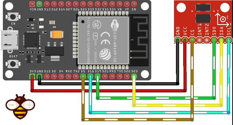
esp32 SPI connection
SPI connection on SS (GPIO05), MOSI (GPIO23), MISO (GPIO19), and SCK (GPIO18) that correspond to CS, SDA, SDO, and SCL pins.
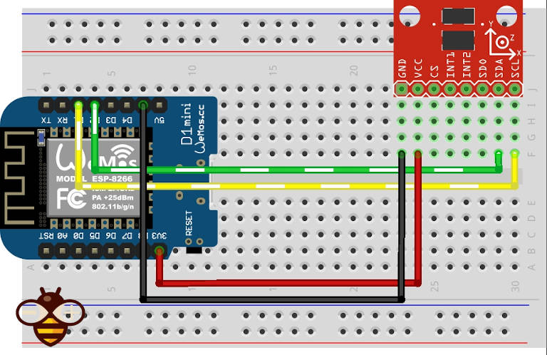
esp8266 i2c connection
On esp8266 D4 on SDA and D5 on SCL.
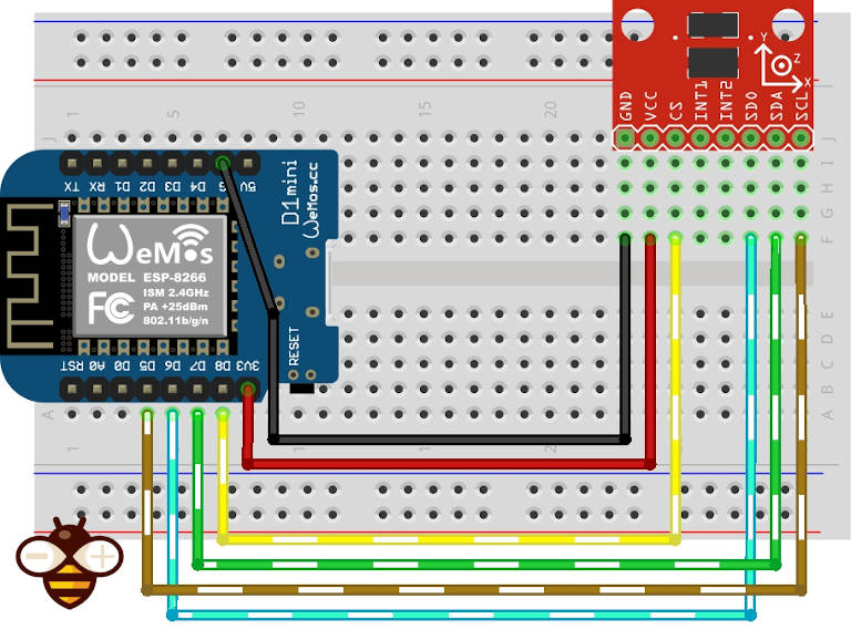
esp8266 SPI connection
esp8266 with SPI SS (D8) on CS, D7 (MOSI) on SDA, D6 (MISO) on SDO, and D5 (SCK) on SCL.
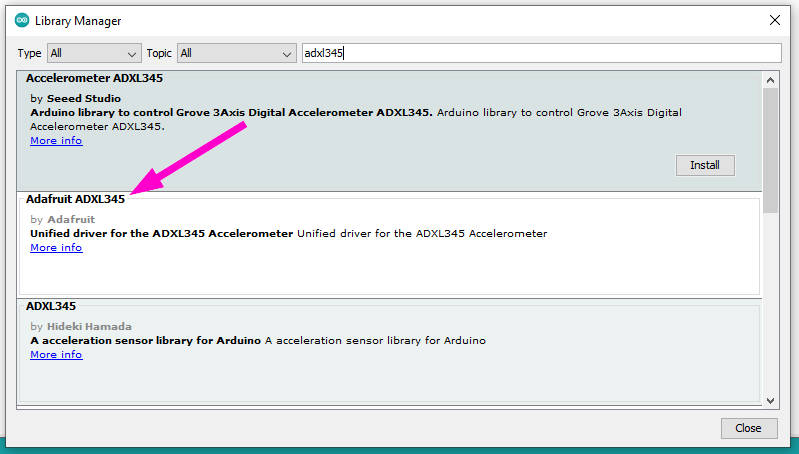
Library Adafruit no interrupt
Exist a lot of libraries, but one of the most simple It’s the Adafruit one. You can get It from GitHub with the relative dependencies Adafruit Unified Sensor Driver, or directly from Arduino IDE library manager.
Basic sketch
Here is a simple sketch (from a library example) with an i2c connection that grabs the data from the accelerometer.
#include <Wire.h>
#include <Adafruit_Sensor.h>
#include <Adafruit_ADXL345_U.h>

/* Assign a unique ID to this sensor at the same time */
Adafruit_ADXL345_Unified accel = Adafruit_ADXL345_Unified(12345);

void displaySensorDetails(void)
{
  sensor_t sensor;
  accel.getSensor(&sensor);
  Serial.println("------------------------------------");
  Serial.print  ("Sensor:       "); Serial.println(sensor.name);
  Serial.print  ("Driver Ver:   "); Serial.println(sensor.version);
  Serial.print  ("Unique ID:    "); Serial.println(sensor.sensor_id);
  Serial.print  ("Max Value:    "); Serial.print(sensor.max_value); Serial.println(" m/s^2");
  Serial.print  ("Min Value:    "); Serial.print(sensor.min_value); Serial.println(" m/s^2");
  Serial.print  ("Resolution:   "); Serial.print(sensor.resolution); Serial.println(" m/s^2");
  Serial.println("------------------------------------");
  Serial.println("");
  delay(500);
}

void displayDataRate(void)
{
  Serial.print  ("Data Rate:    ");

  switch(accel.getDataRate())
  {
    case ADXL345_DATARATE_3200_HZ:
      Serial.print  ("3200 ");
      break;
    case ADXL345_DATARATE_1600_HZ:
      Serial.print  ("1600 ");
      break;
    case ADXL345_DATARATE_800_HZ:
      Serial.print  ("800 ");
      break;
    case ADXL345_DATARATE_400_HZ:
      Serial.print  ("400 ");
      break;
    case ADXL345_DATARATE_200_HZ:
      Serial.print  ("200 ");
      break;
    case ADXL345_DATARATE_100_HZ:
      Serial.print  ("100 ");
      break;
    case ADXL345_DATARATE_50_HZ:
      Serial.print  ("50 ");
      break;
    case ADXL345_DATARATE_25_HZ:
      Serial.print  ("25 ");
      break;
    case ADXL345_DATARATE_12_5_HZ:
      Serial.print  ("12.5 ");
      break;
    case ADXL345_DATARATE_6_25HZ:
      Serial.print  ("6.25 ");
      break;
    case ADXL345_DATARATE_3_13_HZ:
      Serial.print  ("3.13 ");
      break;
    case ADXL345_DATARATE_1_56_HZ:
      Serial.print  ("1.56 ");
      break;
    case ADXL345_DATARATE_0_78_HZ:
      Serial.print  ("0.78 ");
      break;
    case ADXL345_DATARATE_0_39_HZ:
      Serial.print  ("0.39 ");
      break;
    case ADXL345_DATARATE_0_20_HZ:
      Serial.print  ("0.20 ");
      break;
    case ADXL345_DATARATE_0_10_HZ:
      Serial.print  ("0.10 ");
      break;
    default:
      Serial.print  ("???? ");
      break;
  }
  Serial.println(" Hz");
}

void displayRange(void)
{
  Serial.print  ("Range:         +/- ");

  switch(accel.getRange())
  {
    case ADXL345_RANGE_16_G:
      Serial.print  ("16 ");
      break;
    case ADXL345_RANGE_8_G:
      Serial.print  ("8 ");
      break;
    case ADXL345_RANGE_4_G:
      Serial.print  ("4 ");
      break;
    case ADXL345_RANGE_2_G:
      Serial.print  ("2 ");
      break;
    default:
      Serial.print  ("?? ");
      break;
  }
  Serial.println(" g");
}

void setup(void)
{
#ifndef ESP8266
  while (!Serial); // for Leonardo/Micro/Zero
#endif
  Serial.begin(9600);
  Serial.println("Accelerometer Test"); Serial.println("");

  /* Initialise the sensor */
  if(!accel.begin())
  {
    /* There was a problem detecting the ADXL345 ... check your connections */
    Serial.println("Ooops, no ADXL345 detected ... Check your wiring!");
    while(1);
  }

  /* Set the range to whatever is appropriate for your project */
  accel.setRange(ADXL345_RANGE_16_G);
  // accel.setRange(ADXL345_RANGE_8_G);
  // accel.setRange(ADXL345_RANGE_4_G);
  // accel.setRange(ADXL345_RANGE_2_G);

  /* Display some basic information on this sensor */
  displaySensorDetails();

  /* Display additional settings (outside the scope of sensor_t) */
  displayDataRate();
  displayRange();
  Serial.println("");
}

void loop(void)
{
  /* Get a new sensor event */
  sensors_event_t event;
  accel.getEvent(&event);

  /* Display the results (acceleration is measured in m/s^2) */
  Serial.print("X: "); Serial.print(event.acceleration.x); Serial.print("  ");
  Serial.print("Y: "); Serial.print(event.acceleration.y); Serial.print("  ");
  Serial.print("Z: "); Serial.print(event.acceleration.z); Serial.print("  ");Serial.println("m/s^2 ");
  delay(500);
}
To connect with SPI, you must change the constructor
//Adafruit_ADXL345_Unified accel = Adafruit_ADXL345_Unified(18, 19, 23, 5, 12345); ESP32 equivalent constructor
Adafruit_ADXL345_Unified accel = Adafruit_ADXL345_Unified(SCK, MISO, MOSI, SS, 12345);
Here is the serial output of the script
------------------------------------
Sensor:       ADXL345
Driver Ver:   1
Unique ID:    12345
Max Value:    -156.91 m/s^2
Min Value:    156.91 m/s^2
Resolution:   0.04 m/s^2
------------------------------------

Data Rate:    100  Hz
Range:         +/- 16  g

X: -4.08  Y: -0.78  Z: 8.98  m/s^2
X: -4.04  Y: -0.78  Z: 8.94  m/s^2
X: -4.08  Y: -0.78  Z: 8.83  m/s^2
X: -4.08  Y: -0.75  Z: 8.90  m/s^2
X: -4.04  Y: -0.78  Z: 8.94  m/s^2
X: -4.08  Y: -0.78  Z: 8.98  m/s^2
X: -4.08  Y: -0.75  Z: 8.90  m/s^2
X: -4.00  Y: -0.78  Z: 8.90  m/s^2
X: -4.08  Y: -0.75  Z: 8.90  m/s^2
X: -4.08  Y: -0.75  Z: 8.94  m/s^2
X: -4.04  Y: -0.78  Z: 8.90  m/s^2
X: -4.04  Y: -0.78  Z: 8.94  m/s^2
X: -4.04  Y: -0.78  Z: 8.94  m/s^2
Library SparkFun with interrupt
This device offers a good series of interrupt modes, which are very useful in smart/bio-metric logging. Here is the information from the datasheet.
DATA_READY
The DATA_READY bit is set when new data is available and is cleared when It is no more available.
SINGLE_TAP
The SINGLE_TAP bit is set when a single acceleration event that is greater than the value in the THRESH_TAP register (Address 0x1D) occurs for less time than is specified in the DUR register (Address 0x21).
DOUBLE_TAP
The DOUBLE_TAP bit is set when two acceleration events that are greater than the value in the THRESH_TAP register (Address 0x1D) occur for less time than is specified in the DUR register (Address 0x21), with the second tap starting after the time specified by the latent register (Address 0x22) but within the time specified in the window register (Address 0x23).
Activity
The activity bit is set when acceleration greater than the value stored in the THRESH_ACT register (Address 0x24) is experienced on any participating axis, set by the ACT_INACT_CTL register.
(Address 0x27).
Inactivity
The inactivity bit is set when the acceleration of less than the value stored in the THRESH_INACT register (Address 0x25) is experienced for more time than is specified in the TIME_INACT
register (Address 0x26) on all participating axes, as set by the ACT_INACT_CTL register (Address 0x27). The maximum value for TIME_INACT is 255 sec.
FREE_FALL
The FREE_FALL bit is set when the acceleration of less than the value stored in the THRESH_FF register (Address 0x28) is experienced for more time than is specified in the TIME_FF register (Address 0x29) on all axes (logical AND). The FREE_FALL interrupt differs from the inactivity interrupt as follows: all axes always participate and are logically AND’ed, the timer period is much smaller (1.28 sec maximum), and the mode of operation is always dc-coupled.
Watermark
The watermark bit is set when the number of samples in FIFO equals the value stored in the sample bits (Register FIFO_CTL, Address 0x38). The watermark bit is cleared automatically when
FIFO is read, and the content returns to a value below the value stored in the sample bits.
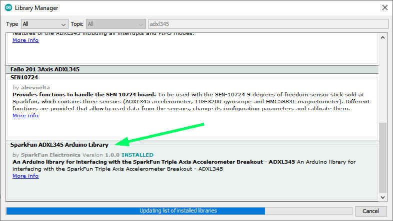
Get library
The SparkFun library It’s quite a complex library but offers support to i2c and SPI and gives us the possibility to manage all the interrupt described up. You can get It from GitHub, or directly from the Arduino IDE library manager.
The code offer a complete example of interrupt usage.
/*  *********************************************
 *  SparkFun_ADXL345_Example
 *  Triple Axis Accelerometer Breakout - ADXL345
 *  Hook Up Guide Example
 *
 *  Utilizing Sparkfun's ADXL345 Library
 *  Bildr ADXL345 source file modified to support
 *  both I2C and SPI Communication
 *
 *  E.Robert @ SparkFun Electronics
 *  Created: Jul 13, 2016
 *  Updated: Sep 06, 2016
 *
 *  Development Environment Specifics:
 *  Arduino 1.6.11
 *
 *  Hardware Specifications:
 *  SparkFun ADXL345
 *  Arduino Uno
 *  *********************************************/

#include <SparkFun_ADXL345.h>         // SparkFun ADXL345 Library

/*********** COMMUNICATION SELECTION ***********/
/*    Comment Out The One You Are Not Using    */
ADXL345 adxl = ADXL345(10);           // USE FOR SPI COMMUNICATION, ADXL345(CS_PIN);
//ADXL345 adxl = ADXL345();             // USE FOR I2C COMMUNICATION

/****************** INTERRUPT ******************/
/*      Uncomment If Attaching Interrupt       */
//int interruptPin = 2;                 // Setup pin 2 to be the interrupt pin (for most Arduino Boards)

void ADXL_ISR();
/******************** SETUP ********************/
/*          Configure ADXL345 Settings         */
void setup(){

  Serial.begin(9600);                 // Start the serial terminal
  Serial.println("SparkFun ADXL345 Accelerometer Hook Up Guide Example");
  Serial.println();

  adxl.powerOn();                     // Power on the ADXL345

  adxl.setRangeSetting(16);           // Give the range settings
                                      // Accepted values are 2g, 4g, 8g or 16g
                                      // Higher Values = Wider Measurement Range
                                      // Lower Values = Greater Sensitivity

  adxl.setSpiBit(0);                  // Configure the device to be in 4 wire SPI mode when set to '0' or 3 wire SPI mode when set to 1
                                      // Default: Set to 1
                                      // SPI pins on the ATMega328: 11, 12 and 13 as reference in SPI Library

  adxl.setActivityXYZ(1, 0, 0);       // Set to activate movement detection in the axes "adxl.setActivityXYZ(X, Y, Z);" (1 == ON, 0 == OFF)
  adxl.setActivityThreshold(75);      // 62.5mg per increment   // Set activity   // Inactivity thresholds (0-255)

  adxl.setInactivityXYZ(1, 0, 0);     // Set to detect inactivity in all the axes "adxl.setInactivityXYZ(X, Y, Z);" (1 == ON, 0 == OFF)
  adxl.setInactivityThreshold(75);    // 62.5mg per increment   // Set inactivity // Inactivity thresholds (0-255)
  adxl.setTimeInactivity(10);         // How many seconds of no activity is inactive?

  adxl.setTapDetectionOnXYZ(0, 0, 1); // Detect taps in the directions turned ON "adxl.setTapDetectionOnX(X, Y, Z);" (1 == ON, 0 == OFF)

  // Set values for what is considered a TAP and what is a DOUBLE TAP (0-255)
  adxl.setTapThreshold(50);           // 62.5 mg per increment
  adxl.setTapDuration(15);            // 625 μs per increment
  adxl.setDoubleTapLatency(80);       // 1.25 ms per increment
  adxl.setDoubleTapWindow(200);       // 1.25 ms per increment

  // Set values for what is considered FREE FALL (0-255)
  adxl.setFreeFallThreshold(7);       // (5 - 9) recommended - 62.5mg per increment
  adxl.setFreeFallDuration(30);       // (20 - 70) recommended - 5ms per increment

  // Setting all interupts to take place on INT1 pin
  //adxl.setImportantInterruptMapping(1, 1, 1, 1, 1);     // Sets "adxl.setEveryInterruptMapping(single tap, double tap, free fall, activity, inactivity);"
                                                        // Accepts only 1 or 2 values for pins INT1 and INT2. This chooses the pin on the ADXL345 to use for Interrupts.
                                                        // This library may have a problem using INT2 pin. Default to INT1 pin.

  // Turn on Interrupts for each mode (1 == ON, 0 == OFF)
  adxl.InactivityINT(1);
  adxl.ActivityINT(1);
  adxl.FreeFallINT(1);
  adxl.doubleTapINT(1);
  adxl.singleTapINT(1);

//attachInterrupt(digitalPinToInterrupt(interruptPin), ADXL_ISR, RISING);   // Attach Interrupt

}

/****************** MAIN CODE ******************/
/*     Accelerometer Readings and Interrupt    */
void loop(){

  // Accelerometer Readings
  int x,y,z;
  adxl.readAccel(&x, &y, &z);         // Read the accelerometer values and store them in variables declared above x,y,z

  // Output Results to Serial
  /* UNCOMMENT TO VIEW X Y Z ACCELEROMETER VALUES */
  //Serial.print(x);
  //Serial.print(", ");
  //Serial.print(y);
  //Serial.print(", ");
  //Serial.println(z);

  ADXL_ISR();
  // You may also choose to avoid using interrupts and simply run the functions within ADXL_ISR();
  //  and place it within the loop instead.
  // This may come in handy when it doesn't matter when the action occurs.

}

/********************* ISR *********************/
/* Look for Interrupts and Triggered Action    */
void ADXL_ISR() {

  // getInterruptSource clears all triggered actions after returning value
  // Do not call again until you need to recheck for triggered actions
  byte interrupts = adxl.getInterruptSource();

  // Free Fall Detection
  if(adxl.triggered(interrupts, ADXL345_FREE_FALL)){
    Serial.println("*** FREE FALL ***");
    //add code here to do when free fall is sensed
  }

  // Inactivity
  if(adxl.triggered(interrupts, ADXL345_INACTIVITY)){
    Serial.println("*** INACTIVITY ***");
     //add code here to do when inactivity is sensed
  }

  // Activity
  if(adxl.triggered(interrupts, ADXL345_ACTIVITY)){
    Serial.println("*** ACTIVITY ***");
     //add code here to do when activity is sensed
  }

  // Double Tap Detection
  if(adxl.triggered(interrupts, ADXL345_DOUBLE_TAP)){
    Serial.println("*** DOUBLE TAP ***");
     //add code here to do when a 2X tap is sensed
  }

  // Tap Detection
  if(adxl.triggered(interrupts, ADXL345_SINGLE_TAP)){
    Serial.println("*** TAP ***");
     //add code here to do when a tap is sensed
  }
}
As you can see, the library support i2c and SPI, and you can set a lot of data to specify the sensitivity of the device and interrupt parameters.
I change the example to use pin GPIO15 pin of esp32 as an interrupt for some activity like TAP or DOUBLE TAP and GPIO4 to intercept 5 seconds of inactivity.
/*  *********************************************
 *  ADXL345
 *  Triple Axis Accelerometer Breakout - ADXL345
 *  Utilizing Sparkfun's ADXL345 Library
 *  both I2C and SPI Communication with esp32
 *
 *
 *
 *  *********************************************/

#include <SparkFun_ADXL345.h>         // SparkFun ADXL345 Library

/*********** COMMUNICATION SELECTION ***********/
/*    Comment Out The One You Are Not Using    */
//ADXL345 adxl = ADXL345(10);           // USE FOR SPI COMMUNICATION, ADXL345(CS_PIN);
ADXL345 adxl = ADXL345();             // USE FOR I2C COMMUNICATION

/****************** INTERRUPT ******************/
/*      Uncomment If Attaching Interrupt       */
//int interruptPin = 2;                 // Setup pin 2 to be the interrupt pin (for most Arduino Boards)
volatile bool somethingAppend = false;
volatile bool nothingAppend = false;

void IRAM_ATTR pin1Interrupt() {
	somethingAppend = true;
}
void IRAM_ATTR pin2Interrupt() {
	nothingAppend = true;
}

/******************** SETUP ********************/
/*          Configure ADXL345 Settings         */
void setup(){

  Serial.begin(9600);                 // Start the serial terminal
  Serial.println("SparkFun ADXL345 Accelerometer Hook Up Guide Example");
  Serial.println();

  adxl.powerOn();                     // Power on the ADXL345

  adxl.setRangeSetting(16);           // Give the range settings
                                      // Accepted values are 2g, 4g, 8g or 16g
                                      // Higher Values = Wider Measurement Range
                                      // Lower Values = Greater Sensitivity

  adxl.setSpiBit(0);                  // Configure the device to be in 4 wire SPI mode when set to '0' or 3 wire SPI mode when set to 1
                                      // Default: Set to 1
                                      // SPI pins on the ATMega328: 11, 12 and 13 as reference in SPI Library

  adxl.setActivityXYZ(1, 0, 0);       // Set to activate movement detection in the axes "adxl.setActivityXYZ(X, Y, Z);" (1 == ON, 0 == OFF)
  adxl.setActivityThreshold(75);      // 62.5mg per increment   // Set activity   // Inactivity thresholds (0-255)

  adxl.setInactivityXYZ(1, 0, 0);     // Set to detect inactivity in all the axes "adxl.setInactivityXYZ(X, Y, Z);" (1 == ON, 0 == OFF)
  adxl.setInactivityThreshold(75);    // 62.5mg per increment   // Set inactivity // Inactivity thresholds (0-255)
  adxl.setTimeInactivity(5);         // How many seconds of no activity is inactive?

  adxl.setTapDetectionOnXYZ(0, 0, 1); // Detect taps in the directions turned ON "adxl.setTapDetectionOnX(X, Y, Z);" (1 == ON, 0 == OFF)

  // Set values for what is considered a TAP and what is a DOUBLE TAP (0-255)
  adxl.setTapThreshold(50);           // 62.5 mg per increment
  adxl.setTapDuration(15);            // 625 μs per increment
  adxl.setDoubleTapLatency(80);       // 1.25 ms per increment
  adxl.setDoubleTapWindow(200);       // 1.25 ms per increment

  // Set values for what is considered FREE FALL (0-255)
  adxl.setFreeFallThreshold(7);       // (5 - 9) recommended - 62.5mg per increment
  adxl.setFreeFallDuration(30);       // (20 - 70) recommended - 5ms per increment

  // Setting all interupts to take place on INT1 pin except inactivity on INT2
  adxl.setImportantInterruptMapping(1, 1, 1, 1, 2);     // Sets "adxl.setEveryInterruptMapping(single tap, double tap, free fall, activity, inactivity);"
                                                        // Accepts only 1 or 2 values for pins INT1 and INT2. This chooses the pin on the ADXL345 to use for Interrupts.
                                                        // This library may have a problem using INT2 pin. Default to INT1 pin.

  // Turn on Interrupts for each mode (1 == ON, 0 == OFF)
  adxl.InactivityINT(1);
  adxl.ActivityINT(1);
  adxl.FreeFallINT(1);
  adxl.doubleTapINT(1);
  adxl.singleTapINT(1);

//attachInterrupt(digitalPinToInterrupt(interruptPin), ADXL_ISR, RISING);   // Attach Interrupt
  pinMode(GPIO_NUM_4, INPUT);
  pinMode(GPIO_NUM_15, INPUT);

  attachInterrupt(digitalPinToInterrupt(GPIO_NUM_4), pin1Interrupt, RISING);
  attachInterrupt(digitalPinToInterrupt(GPIO_NUM_15), pin2Interrupt, RISING);

}

void ADXL_ISR();

#define INTERVAL 1000
unsigned long startTime = millis();

/****************** MAIN CODE ******************/
/*     Accelerometer Readings and Interrupt    */
void loop(){

  // Accelerometer Readings
  int x,y,z;
  adxl.readAccel(&x, &y, &z);         // Read the accelerometer values and store them in variables declared above x,y,z

  if (startTime + INTERVAL < millis()){
	  // Output Results to Serial
	  /* X Y Z ACCELEROMETER VALUES */
		Serial.print("values of X , Y , Z: ");
		Serial.print(x);
		Serial.print(" , ");
		Serial.print(y);
		Serial.print(" , ");
		Serial.println(z);

		double xyzG[3];
		double ax,ay,az;
		adxl.get_Gxyz(xyzG);
		ax = xyzG[0];
		ay = xyzG[1];
		az = xyzG[2];
		Serial.print("X=");
		Serial.print(ax);
	    Serial.print(" g");
		Serial.print(" Y=");
		Serial.print(ay);
	    Serial.print(" g");
		Serial.print(" Z=");
		Serial.print(az);
	    Serial.println(" g");
		Serial.println("**********************");

		  if (somethingAppend) {
		  	Serial.println(" ------> Something append!!");
		  	ADXL_ISR();
		  	somethingAppend = false;
		  }
		  if (nothingAppend) {
		      	Serial.println(" ------> Nothing append in the last 5 secs.!!");
		      	ADXL_ISR();
		      	nothingAppend = false;
			}

	  startTime = millis();
  }
}

/********************* ISR *********************/
/* Look for Interrupts and Triggered Action    */
void ADXL_ISR() {

  // getInterruptSource clears all triggered actions after returning value
  // Do not call again until you need to recheck for triggered actions
  byte interrupts = adxl.getInterruptSource();

  // Free Fall Detection
  if(adxl.triggered(interrupts, ADXL345_FREE_FALL)){
    Serial.println("*** FREE FALL ***");
    //add code here to do when free fall is sensed
  }

  // Inactivity
  if(adxl.triggered(interrupts, ADXL345_INACTIVITY)){
    Serial.println("*** INACTIVITY ***");
     //add code here to do when inactivity is sensed
  }

  // Activity
//  if(adxl.triggered(interrupts, ADXL345_ACTIVITY)){
//    Serial.println("*** ACTIVITY ***");
//     //add code here to do when activity is sensed
//  }

  // Double Tap Detection
  if(adxl.triggered(interrupts, ADXL345_DOUBLE_TAP)){
    Serial.println("*** DOUBLE TAP ***");
     //add code here to do when a 2X tap is sensed
  }

  // Tap Detection
  if(adxl.triggered(interrupts, ADXL345_SINGLE_TAP)){
    Serial.println("*** TAP ***");
     //add code here to do when a tap is sensed
  }
}
Here is the console output of my test.
values of X , Y , Z: -3 , 16 , 27
X=-0.01 g Y=0.06 g Z=0.09 g
**********************
values of X , Y , Z: -3 , 16 , 27
X=-0.01 g Y=0.06 g Z=0.09 g
**********************
 ------> Nothing append in the last 5 secs.!!
*** INACTIVITY ***
values of X , Y , Z: -3 , 16 , 27
X=-0.01 g Y=0.06 g Z=0.09 g
**********************
values of X , Y , Z: -3 , 16 , 27
X=-0.01 g Y=0.06 g Z=0.09 g
**********************
values of X , Y , Z: -3 , 16 , 27
X=-0.01 g Y=0.06 g Z=0.09 g
**********************
values of X , Y , Z: 1 , -2 , 66
X=0.00 g Y=-0.01 g Z=0.23 g
**********************
values of X , Y , Z: -3 , 16 , 27
X=-0.01 g Y=0.06 g Z=0.09 g
**********************
 ------> Something append!!
*** DOUBLE TAP ***
*** TAP ***
values of X , Y , Z: -3 , 16 , 27
X=-0.01 g Y=0.06 g Z=0.09 g
**********************
values of X , Y , Z: -3 , 16 , 27
X=-0.01 g Y=0.06 g Z=0.09 g
**********************
values of X , Y , Z: -3 , 16 , 27
X=-0.01 g Y=0.06 g Z=0.09 g
**********************
values of X , Y , Z: -3 , 16 , 27
X=-0.01 g Y=0.06 g Z=0.09 g
**********************
values of X , Y , Z: -3 , 16 , 27
X=-0.01 g Y=0.06 g Z=0.09 g
**********************
 ------> Nothing append in the last 5 secs.!!
*** INACTIVITY ***
values of X , Y , Z: -3 , 16 , 27
X=-0.01 g Y=0.06 g Z=0.09 g
**********************
Estimating the Inclination Angle with an Accelerometer
As written we can get a good measurement of the current inclination angle in order, for example, to control the robot’s movements. Let’s first examine how to use an accelerometer alone to measure the inclination angle.
Suppose that the robot is in a stationary position illustrated below (viewed from the side, the accelerometer is placed on the top of the robot, perpendicular to the body):
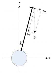
The inclination angle can be calculated as:
cos(Axr) = Rx / R
cos(Ayr) = Ry / R
cos(Azr) = Rz / R
R = SQRT( Rx^2 + Ry^2 + Rz^2)
Find angles by using arccos() function (the inverse cos() function ):
Axr = arccos(Rx/R)
Ayr = arccos(Ry/R)
Azr = arccos(Rz/R)
So the function to calculate the angle from 0 positions become
float inclination=180.0*acos(az/sqrt(ax*ax+ay*ay+az*az))/M_PI;
if you want “reset” the initial position, you can use this function that compensates for the initial ax0, ay0 and az0 values.
float inclinationFromInitialValue = 180.0*acos( (ax0*ax + ay0*ay + az0*az)/sqrt( (ax*ax + ay*ay + az*az)*(ax0*ax0 + ay0*ay0 + az0*az0)))/M_PI;
The resulting code is this
/*
 * GY-291 ADXL345 accelerometer test
 * Retrieve data and calculate angle of rotation with gravitational force
 * Angle from 0 of device and angle from initial position of device
 *
 *  by Mischianti Renzo <https://mischianti.org>
 *
 *  https://mischianti.org
 *
 */
#include <Wire.h>
#include <Adafruit_Sensor.h>
#include <Adafruit_ADXL345_U.h>

/* Assign a unique ID to this sensor at the same time */
//Adafruit_ADXL345_Unified accel = Adafruit_ADXL345_Unified(12345); // i2c connection
//Adafruit_ADXL345_Unified(uint8_t clock, uint8_t miso, uint8_t mosi, uint8_t cs, int32_t sensorID = -1);
//Adafruit_ADXL345_Unified accel = Adafruit_ADXL345_Unified(18, 19, 23, 5, 12345);
Adafruit_ADXL345_Unified accel = Adafruit_ADXL345_Unified(SCK, MISO, MOSI, SS, 12345); // SPI connection

void displaySensorDetails(void)
{
  sensor_t sensor;
  accel.getSensor(&sensor);
  Serial.println("------------------------------------");
  Serial.print  ("Sensor:       "); Serial.println(sensor.name);
  Serial.print  ("Driver Ver:   "); Serial.println(sensor.version);
  Serial.print  ("Unique ID:    "); Serial.println(sensor.sensor_id);
  Serial.print  ("Max Value:    "); Serial.print(sensor.max_value); Serial.println(" m/s^2");
  Serial.print  ("Min Value:    "); Serial.print(sensor.min_value); Serial.println(" m/s^2");
  Serial.print  ("Resolution:   "); Serial.print(sensor.resolution); Serial.println(" m/s^2");
  Serial.println("------------------------------------");
  Serial.println("");
  delay(500);
}

void displayDataRate(void)
{
  Serial.print  ("Data Rate:    ");

  switch(accel.getDataRate())
  {
    case ADXL345_DATARATE_3200_HZ:
      Serial.print  ("3200 ");
      break;
    case ADXL345_DATARATE_1600_HZ:
      Serial.print  ("1600 ");
      break;
    case ADXL345_DATARATE_800_HZ:
      Serial.print  ("800 ");
      break;
    case ADXL345_DATARATE_400_HZ:
      Serial.print  ("400 ");
      break;
    case ADXL345_DATARATE_200_HZ:
      Serial.print  ("200 ");
      break;
    case ADXL345_DATARATE_100_HZ:
      Serial.print  ("100 ");
      break;
    case ADXL345_DATARATE_50_HZ:
      Serial.print  ("50 ");
      break;
    case ADXL345_DATARATE_25_HZ:
      Serial.print  ("25 ");
      break;
    case ADXL345_DATARATE_12_5_HZ:
      Serial.print  ("12.5 ");
      break;
    case ADXL345_DATARATE_6_25HZ:
      Serial.print  ("6.25 ");
      break;
    case ADXL345_DATARATE_3_13_HZ:
      Serial.print  ("3.13 ");
      break;
    case ADXL345_DATARATE_1_56_HZ:
      Serial.print  ("1.56 ");
      break;
    case ADXL345_DATARATE_0_78_HZ:
      Serial.print  ("0.78 ");
      break;
    case ADXL345_DATARATE_0_39_HZ:
      Serial.print  ("0.39 ");
      break;
    case ADXL345_DATARATE_0_20_HZ:
      Serial.print  ("0.20 ");
      break;
    case ADXL345_DATARATE_0_10_HZ:
      Serial.print  ("0.10 ");
      break;
    default:
      Serial.print  ("???? ");
      break;
  }
  Serial.println(" Hz");
}

void displayRange(void)
{
  Serial.print  ("Range:         +/- ");

  switch(accel.getRange())
  {
    case ADXL345_RANGE_16_G:
      Serial.print  ("16 ");
      break;
    case ADXL345_RANGE_8_G:
      Serial.print  ("8 ");
      break;
    case ADXL345_RANGE_4_G:
      Serial.print  ("4 ");
      break;
    case ADXL345_RANGE_2_G:
      Serial.print  ("2 ");
      break;
    default:
      Serial.print  ("?? ");
      break;
  }
  Serial.println(" g");
}

void setup(void)
{
#ifndef ESP8266
  while (!Serial); // for Leonardo/Micro/Zero
#endif
  Serial.begin(9600);
  Serial.println("Accelerometer Test"); Serial.println("");

  /* Initialise the sensor */
  if(!accel.begin())
  {
    /* There was a problem detecting the ADXL345 ... check your connections */
    Serial.println("Ooops, no ADXL345 detected ... Check your wiring!");
    while(1);
  }

  /* Set the range to whatever is appropriate for your project */
  accel.setRange(ADXL345_RANGE_16_G);
  // accel.setRange(ADXL345_RANGE_8_G);
  // accel.setRange(ADXL345_RANGE_4_G);
  // accel.setRange(ADXL345_RANGE_2_G);

  /* Display some basic information on this sensor */
  displaySensorDetails();

  /* Display additional settings (outside the scope of sensor_t) */
  displayDataRate();
  displayRange();
  Serial.println("");
}

bool initialValue = true;

double az0 = 0;
double ax0 = 0;
double ay0 = 0;

void loop(void)
{
  /* Get a new sensor event */
  sensors_event_t event;
  accel.getEvent(&event);

  double az = event.acceleration.z;
  double ax = event.acceleration.x;
  double ay = event.acceleration.y;

  if (initialValue) {
	  az0 = event.acceleration.z;
	  ax0 = event.acceleration.x;
	  ay0 = event.acceleration.y;

	  initialValue = false;
  }

  float inclination=180.0*acos(az/sqrt(ax*ax+ay*ay+az*az))/M_PI;
  Serial.print("Inclination: from 0 -> ");
  Serial.print(inclination);

  float inclinationFromInitialValue = 180.0*acos( (ax0*ax + ay0*ay + az0*az)/sqrt( (ax*ax + ay*ay + az*az)*(ax0*ax0 + ay0*ay0 + az0*az0)))/M_PI;
  Serial.print("° - from initial value -> ");
  Serial.print(inclinationFromInitialValue);

  /* Display the results (acceleration is measured in m/s^2) */
  Serial.print("° - X: "); Serial.print(ax); Serial.print("  ");
  Serial.print("Y: "); Serial.print(ay); Serial.print("  ");
  Serial.print("Z: "); Serial.print(az); Serial.print("  ");Serial.println("m/s^2 ");

  delay(500);
}
The serial output becomes
Accelerometer Test

------------------------------------
Sensor:       ADXL345
Driver Ver:   1
Unique ID:    12345
Max Value:    -156.91 m/s^2
Min Value:    156.91 m/s^2
Resolution:   0.04 m/s^2
------------------------------------

Data Rate:    100  Hz
Range:         +/- 16  g

Inclination: from 0 -> 25.15° - from initial value -> 0.00° - X: -4.16  Y: -0.43  Z: 8.90  m/s^2
Inclination: from 0 -> 24.46° - from initial value -> 0.76° - X: -4.04  Y: -0.47  Z: 8.94  m/s^2
Inclination: from 0 -> 24.76° - from initial value -> 0.48° - X: -4.08  Y: -0.47  Z: 8.90  m/s^2
Inclination: from 0 -> 24.39° - from initial value -> 0.77° - X: -4.00  Y: -0.39  Z: 8.87  m/s^2
Inclination: from 0 -> 24.78° - from initial value -> 0.62° - X: -4.08  Y: -0.51  Z: 8.90  m/s^2
Inclination: from 0 -> 24.88° - from initial value -> 0.57° - X: -4.08  Y: -0.51  Z: 8.87  m/s^2
Inclination: from 0 -> 20.58° - from initial value -> 5.11° - X: -3.26  Y: 0.00  Z: 8.67  m/s^2
Inclination: from 0 -> 52.23° - from initial value -> 28.91° - X: -7.10  Y: 1.41  Z: 5.61  m/s^2
Inclination: from 0 -> 70.47° - from initial value -> 49.04° - X: -8.90  Y: 3.65  Z: 3.41  m/s^2
Inclination: from 0 -> 77.11° - from initial value -> 56.65° - X: -8.71  Y: 4.43  Z: 2.24  m/s^2
Inclination: from 0 -> 87.06° - from initial value -> 68.87° - X: -8.00  Y: 5.88  Z: 0.51  m/s^2
Inclination: from 0 -> 94.68° - from initial value -> 76.98° - X: -7.81  Y: 6.35  Z: -0.82  m/s^2
Inclination: from 0 -> 102.48° - from initial value -> 84.43° - X: -7.69  Y: 6.28  Z: -2.20  m/s^2
Inclination: from 0 -> 102.26° - from initial value -> 84.13° - X: -7.73  Y: 6.24  Z: -2.16  m/s^2
Inclination: from 0 -> 103.35° - from initial value -> 85.46° - X: -7.61  Y: 6.35  Z: -2.35  m/s^2
Inclination: from 0 -> 105.40° - from initial value -> 87.56° - X: -7.37  Y: 6.28  Z: -2.67  m/s^2
Inclination: from 0 -> 97.58° - from initial value -> 78.79° - X: -8.12  Y: 5.88  Z: -1.33  m/s^2
Inclination: from 0 -> 106.23° - from initial value -> 84.68° - X: -8.71  Y: 4.28  Z: -2.82  m/s^2
Inclination: from 0 -> 106.06° - from initial value -> 83.50° - X: -9.02  Y: 3.49  Z: -2.79  m/s^2
Inclination: from 0 -> 112.29° - from initial value -> 89.72° - X: -8.36  Y: 3.33  Z: -3.69  m/s^2
Inclination: from 0 -> 52.47° - from initial value -> 28.98° - X: -9.14  Y: 1.69  Z: 7.14  m/s^2
Inclination: from 0 -> 30.41° - from initial value -> 8.93° - X: -5.06  Y: 0.86  Z: 8.75  m/s^2
Inclination: from 0 -> 24.27° - from initial value -> 17.12° - X: -2.94  Y: 2.12  Z: 8.04  m/s^2


the library sparkfun isn’t working its just running code upto Serial.println(“SparkFun ADXL345 Accelerometer Hook Up Guide Example”); .
Kindly guide
Hi Ammar,
I tested It and it works correctly, It is very strange. Check the wiring and the power supply of your model.
Bye Renzo
Hello! I’m trying to establish a connection via SPI using an esp32 and an ADXL345, but it appears that the code you provided does not work for the SPI connection. The I2C works just fine. I’ve checked my connections over and over again and everything seems fine and I already checked if my esp32 board had the same SPI pins as yours and it does. I don’t know what might me causing this and also tried other sources to establish the connection and none of them work as well. Could you help?
Hi Ivo,
It strange. Try to uncomment the line
//Adafruit_ADXL345_Unified accel = Adafruit_ADXL345_Unified(18, 19, 23, 5, 12345);
instead of the default value
Bye Renzo
Hello Renzo, thank you for your reply. I’ve done what you said and still no connection to the ADXL345 detected.. My wiring is as follows:
esp32 GND – ADXL345 GND
esp32 3.3V – ADXL345 VCC
esp32 G5 – ADXL345 CS
esp32 G19 – ADXL345 SDO
esp32 G21- ADXL345 SDA
esp32 G18 – ADXL345 SCL
Are you by any change available to provide further help in this topic? It is very important to be since the I2C connection is not good enough for my application. Thank you very much in advance.
But is the model the same?
I belive so yes. I have used a code that would detects and prints in the serial monitor my board’s SPI pins and it shows this. This is why I’m 99% sure that the boards are the same. Could you e-mail me so I could send you via E-mail some photos of the wiring and the code I’m using (the same as yours but something might be wrong idk). Once again, I appreciate your efforts in helping me. Means a lot.
17:15:40.113 -> MISO: 19
17:15:40.113 -> SCK: 18
17:15:40.113 -> SS: 5
17:15:41.082 -> MOSI: 23
Hi Ivo,
you can use the forum for that (the comment section can become too much long).
Bye Renzo
Hi, has this issue been resolved? I’m also not able to use spi to interface adxl345 on esp32.
If a forum thread has been created regarding this, please provide the link here.
Hi Abhay,
the library and device worked correctly when I write the article, now I can’t retest It, I must search for the device from my component.
When I get It I rewrite a feedback here.
Bye Renzo
How could I use the sensor interrupt to wake up an esp32 from sleep mode?
Hi Alejandro,
You must put the int pin to an esp32 pin and use GPIO wake up on interrupt signal change.
ESP32 practical power saving: wake up from light sleep via UART and GPIO – 6
Bye Renzo
Hello, the program did not work for me for esp8266. I have the following message:
Hi Emanuel,
It’s difficult to understand, but the message seems clear: there is some issue with the wiring.
Bye Renzo
thanks for answering renzo.
I used the same connection scheme that you posted in the images for “esp8266 SPI connection”. I don’t know what I’m doing wrong.
can I send you a picture of my connection?
I managed to fix it by putting “//” before the while(); of the setup().
But now the values that the serial monitor gives me are all zero
X: 0.00 Y: 0.00 Z: 0.00 m/s^2
X: 0.00 Y: 0.00 Z: 0.00 m/s^2
X: 0.00 Y: 0.00 Z: 0.00 m/s^2