ESP32 practical power saving: wake up from light sleep via UART and GPIO – 6
With the esp32, when using light sleep, deep sleep, or hibernation, you need to select the wake-up source to turn the device back on.
There are many solutions, but for light sleep, there are two more that are very useful in some situations.
Wake-up sources only for Light Sleep
Light sleep has some additional wake-up sources, and remember that this type of sleep has different characteristics; check the previous chapters.
UART wake up source
The UART peripheral contains a feature that allows the chip to wake from a light sleep when it receives a number of positive inputs on the RX pin. This number of positive inputs can be set using the uart_set_wakeup_threshold () function. When ESP32 receives external UART input, it may be necessary to reactivate the chip when input data is available. Note that the character that will trigger the wake-up (and all previous characters) will not be received by the UART after the wake-up. The external device will typically send an additional character to the ESP32 for reactivation before sending the valuable data.
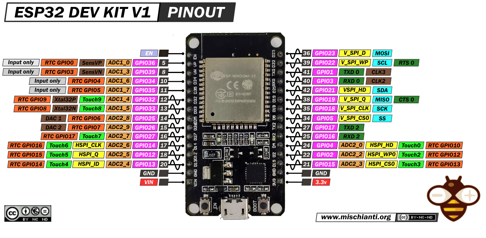
For more information on the device, refer to “DOIT ESP32 DEV KIT v1 high resolution pinout and specs“.
esp_sleep_enable_uart_wakeup() the function can be used to enable this wake-up source.
To set the wake-up source, you need only these two commands:
    uart_set_wakeup_threshold(UART_NUM_0, wake_thresh);
    esp_sleep_enable_uart_wakeup(UART_NUM_0);
Beware that UART_NUM_2 (Serial2) does not work as a wake source, so we use (UART_NUM_0) Serial.
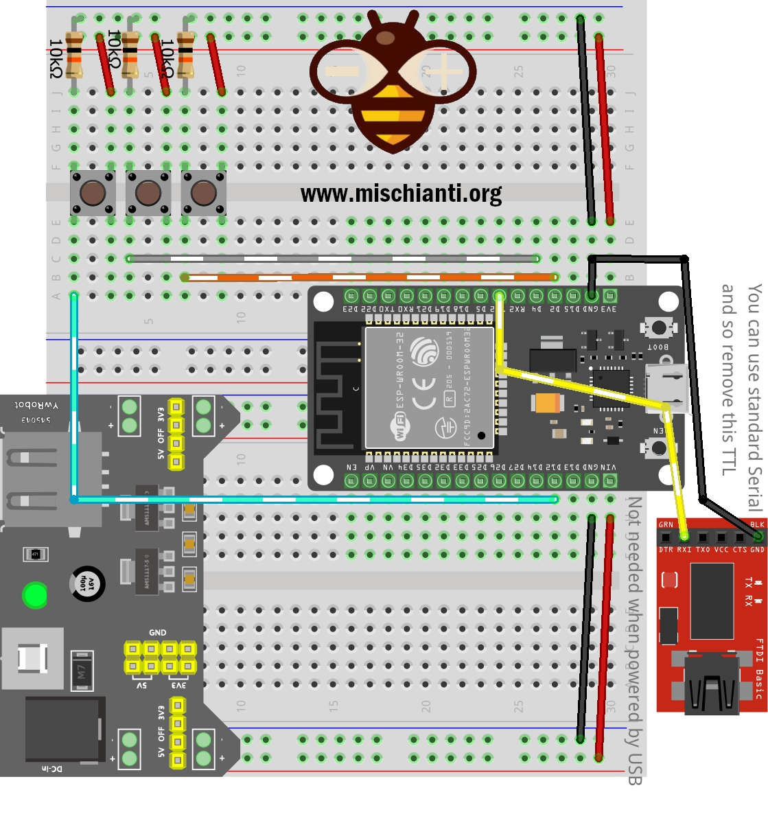
We will use Serial2 to debug; here is the connection schema.
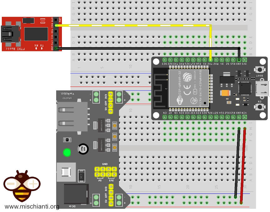
Here is the complete sketch:
/*
 *  ESP32
 *  Light Sleep and Serial (UART) wake up
 *  by Mischianti Renzo <https://mischianti.org>
 *
 *  https://mischianti.org
 *
 */

#include <esp_sleep.h>
#include <driver/uart.h>

int variable = 0;

void setup() {
	Serial2.begin(115200);

	while(!Serial2){delay(500);}

	delay(1000);
    Serial2.print("Variable = ");
    Serial2.println(variable);

    variable += 10;

    Serial2.println();
    Serial2.println("LIGHT SLEEP ENABLED FOR 5secs");
    delay(100);

    int wake_thresh = 3;
//    int wake_thresh = 0x3ff;

    uart_set_wakeup_threshold(UART_NUM_0, wake_thresh);
    esp_sleep_enable_uart_wakeup(UART_NUM_0);

    esp_light_sleep_start();

	Serial.begin(115200);
	while(!Serial){delay(500);}
	// Clean Serial from wake up message
	Serial.flush();
	Serial.readString();

    Serial2.println();
    Serial2.println("LIGHT SLEEP WAKE UP");

    Serial2.print("Variable = ");
    Serial2.println(variable);
}

void loop() {
    while (Serial.available()>0){
    	Serial2.write(Serial.read());
    }
}
Here are the Serial (COM26) and Serial2 (COM3) outputs:
Variable = 0

LIGHT SLEEP ENABLED

>>Send to COM26: "mess"<<

LIGHT SLEEP WAKE UP
Variable = 10

>>Send to COM26: "prova"<<
prova
>>Send to COM26: "prova2"<<
prova2
GPIO wake up source
In addition to EXT0 and EXT1 wake-up sources described above, one more wake-up method from external inputs is available in light sleep mode. With this wake-up source, each pin can be individually configured to trigger wake-up on high or low levels using gpio_wakeup_enable() function, instead, I remember that the EXT0 and EXT1 wake-up sources can only be used with the RTC I / O; this wake-up source can be used with any I / O (RTC or digital).
The function
esp_err_t gpio_wakeup_enable(gpio_num_t gpio_num, gpio_int_type_t intr_type)
Enable GPIO wake-up function.
ReturnESP_OK SuccessESP_ERR_INVALID_ARG Parameter error
Parametersgpio_num: GPIO number.intr_type: GPIO wake-up type. Only GPIO_INTR_LOW_LEVEL or GPIO_INTR_HIGH_LEVEL can be used.
Then, you must enable this wake-up mode with esp_sleep_enable_gpio_wakeup();
/*
 *  ESP32
 *  Light Sleep and GPIO wake up
 *  by Mischianti Renzo <https://mischianti.org>
 *
 *  https://mischianti.org
 *
 */

#include <esp_sleep.h>

int variable = 0;

void setup() {
	Serial2.begin(115200);

	while(!Serial2){delay(500);}

	delay(1000);
    Serial2.print("Variable = ");
    Serial2.println(variable);

    variable += 10;

    Serial2.println();
    Serial2.println("LIGHT SLEEP ENABLED");
    delay(100);

    gpio_wakeup_enable(GPIO_NUM_4, GPIO_INTR_HIGH_LEVEL);
    esp_sleep_enable_gpio_wakeup();

    esp_light_sleep_start();

	Serial.begin(115200);
	while(!Serial){delay(500);}
	// Clean Serial from wake up message
	Serial.flush();
	Serial.readString();

    Serial2.println();
    Serial2.println("LIGHT SLEEP WAKE UP");

    Serial2.print("Variable = ");
    Serial2.println(variable);
}

void loop() {
    while (Serial.available()>0){
    	Serial2.write(Serial.read());
    }
}
Thanks
- ESP32: pinout, specs and Arduino IDE configuration
- ESP32: integrated SPIFFS Filesystem
- ESP32: manage multiple Serial and logging
- ESP32 practical power saving
- ESP32 practical power saving: manage WiFi and CPU
- ESP32 practical power saving: modem and light sleep
- ESP32 practical power saving: deep sleep and hibernation
- ESP32 practical power saving: preserve data, timer and touch wake up
- ESP32 practical power saving: external and ULP wake up
- ESP32 practical power saving: UART and GPIO wake up
- ESP32: integrated LittleFS FileSystem
- ESP32: integrated FFat (Fat/exFAT) FileSystem
- ESP32-wroom-32
- ESP32-CAM
- ESP32: use ethernet w5500 with plain (HTTP) and SSL (HTTPS)
- ESP32: use ethernet enc28j60 with plain (HTTP) and SSL (HTTPS)
- How to use SD card with esp32
- esp32 and esp8266: FAT filesystem on external SPI flash memory
- Firmware and OTA update management
- Firmware management
- OTA update with Arduino IDE
- OTA update with Web Browser
- Self OTA uptate from HTTP server
- Non-standard Firmware update
- Integrating LAN8720 with ESP32 for Ethernet Connectivity with plain (HTTP) and SSL (HTTPS)
- Connecting the EByte E70 to ESP32 c3/s3 devices and a simple sketch example
- ESP32-C3: pinout, specs and Arduino IDE configuration
- Integrating W5500 with ESP32 Using Core 3: Native Ethernet Protocol Support with SSL and Other Features
- Integrating LAN8720 with ESP32 Using Core 3: Native Ethernet Protocol Support with SSL and Other Features