Connecting the EByte E70 to ESP32 c3/s3 devices and a simple sketch example
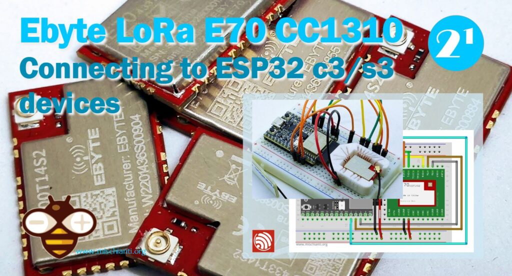
Welcome back to our series on connecting the EByte E70 to various devices! In this article, we’ll walk you through a simple sketch example that will help you establish a connection between the EByte E70 and your ESP32, ESP32C3, or ESP32 S3 device.
Understanding the EByte E70
The EByte E70 is a high-performance RF transceiver module, renowned for its long-range communication capabilities and low power consumption. Designed for wireless communication over large distances, it operates in the sub-GHz frequency bands, making it ideal for IoT applications that require reliable and efficient communication over wide areas.
Prerequisites
Before we begin, make sure you have the following:
- An ESP32, ESP32C3, or ESP32 S3 device
- The EByte E70 module with a breadboard adapter
- An Arduino IDE installed on your computer
- The necessary USB cables to connect your ESP32 device and EByte E70 module to your computer
- Breadboard
Here the basic ESP32 ESP32 Dev Kit v1 - TTGO T-Display 1.14 ESP32 - NodeMCU V3 V2 ESP8266 Lolin32 - NodeMCU ESP-32S - WeMos Lolin32 - WeMos Lolin32 mini - ESP32-CAM programmer - ESP32-CAM bundle - ESP32-WROOM-32 - ESP32-S
Here the ESP32c3 variants LuatOS esp32c3 Core - ESP32-C3-DevKitC-02 - ESP32-C3-MINI-1 - WeMos LOLIN C3 PICO - WeMos LOLIN C3 Mini v2.1 - WeMos LOLIN C3 Mini v1.0 - ESP32 S3 Purlple AI-S3
Here the ESP32s3 variants ESP32 S3 Purlple AI-S3 - YD-ESP32-S3 - ESP32-S3-DevKitC-1 - ESP32-S3-DevKitC-1 - ESP32-S3 Board screen
Here the E70 LoRa variants E70 433/915 T S/S2 - E70 433/915 MT S
Setting up the Hardware
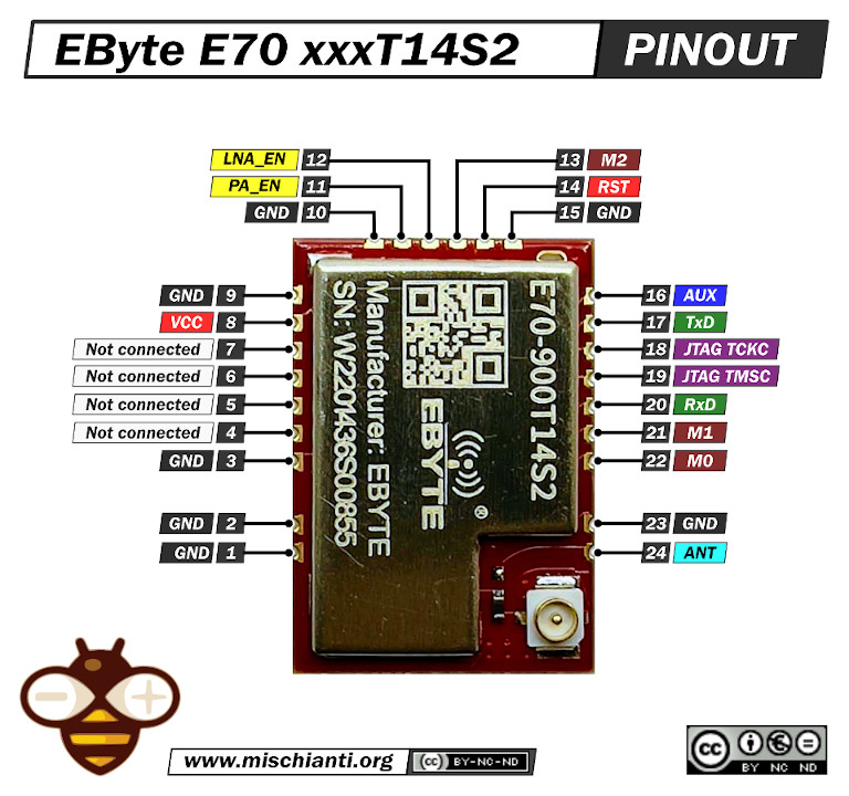
Pinout E70 xxxT14S2
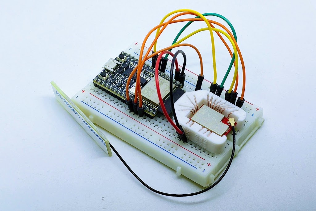
I will use an E70 S2 version for my test because It’s a comfortable form factor with an onboard SMA antenna.
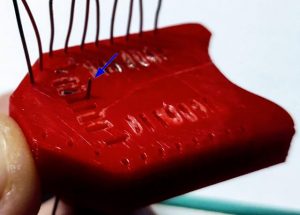
3D printed socket for breadboard
I created a simple socket with my 3D printer to quickly prototype (and manage) the E70 S2; here is the 3D model and the result on a breadboard.
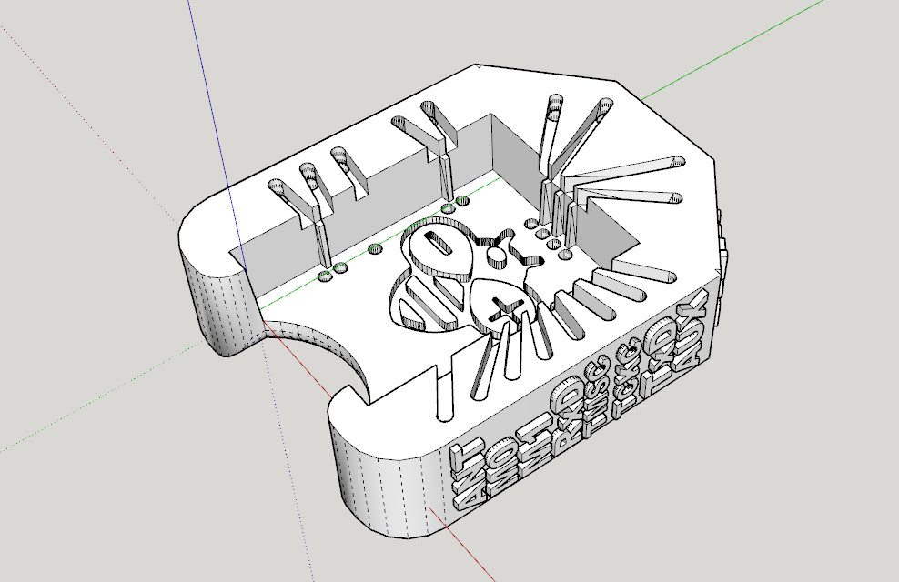
It’s very simple and uses the same technique as other sockets I already created.
After printing, you must add writing inside the hole.
Insert it into the innermost holes and push it out about 3mm
Bend the wire to the external of the adapter.
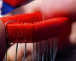
Cut the external part of the wire, and extract,
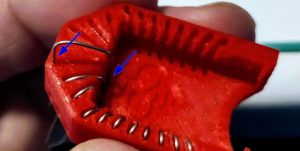
then reinsert in the internal and external holes.
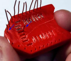
Now check if you need to cut more of the wire of the internal hole and bend It.
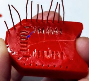
Repeat for all pins. The result It’s very satisfying.
Wiring
esp32
The esp32 is my reference for this article, it is surely perfect for all situations and widely diffused.
Here the connection diagram.
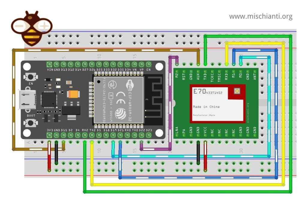
| E70 | ESP32 |
|---|---|
| M0 | 19 |
| M1 | 21 |
| M2 | 22 |
| TX | RX2 |
| RX | TX2 |
| AUX | 15 |
| VCC | 3.3v |
| GND | GND |
Constructor
RF_E70 e70ttl(&Serial2, 15, 19, 21, 22);
esp32c3
I think one of the most interesting microcontrollers for remote client devices is the esp32c3 series because it is very powerful with low power consumption.
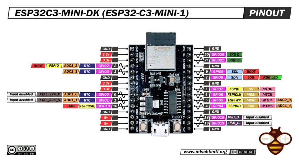
The connection diagram with the socket adapter becomes.
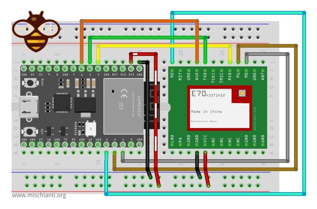
| E70 | ESP32c3 |
|---|---|
| M0 | 1 |
| M1 | 2 |
| M2 | 3 |
| TX | 4 |
| RX | 5 |
| AUX | 6 |
| VCC | 3.3v |
| GND | GND |
Constructor
RF_E70 e70ttl(&Serial1, 1, 2, 3, 4);
ESP32s3
A powerful device like the S3 can be used for more complex operations.
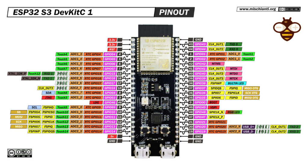
Wiring.
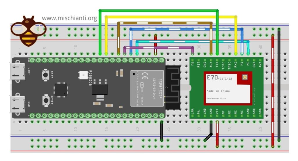
| E70 | ESP32c3 |
|---|---|
| M0 | 5 |
| M1 | 6 |
| M2 | 7 |
| TX | RX1 |
| RX | TX1 |
| AUX | 4 |
| VCC | 3.3v |
| GND | GND |
Constructor
RF_E70 e70ttl(&Serial1, 4, 5, 6, 7);
Configuring the Arduino IDE
Before uploading the sketch to our ESP32 device, we must configure the Arduino IDE to recognize the board and the EByte E70 module. You can find a lot of information about these devices on this site.
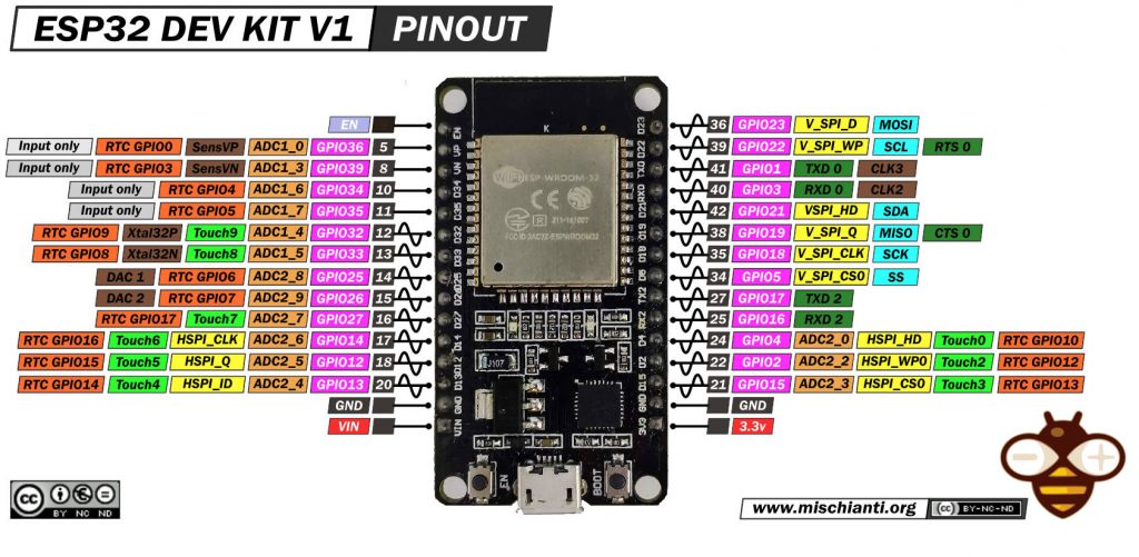
- ESP32: pinout, specs and Arduino IDE configuration
- ESP32: integrated SPIFFS Filesystem
- ESP32: manage multiple Serial and logging
- ESP32 practical power saving
- ESP32 practical power saving: manage WiFi and CPU
- ESP32 practical power saving: modem and light sleep
- ESP32 practical power saving: deep sleep and hibernation
- ESP32 practical power saving: preserve data, timer and touch wake up
- ESP32 practical power saving: external and ULP wake up
- ESP32 practical power saving: UART and GPIO wake up
- ESP32: integrated LittleFS FileSystem
- ESP32: integrated FFat (Fat/exFAT) FileSystem
- ESP32-wroom-32
- ESP32-CAM
- ESP32: use ethernet w5500 with plain (HTTP) and SSL (HTTPS)
- ESP32: use ethernet enc28j60 with plain (HTTP) and SSL (HTTPS)
- How to use SD card with esp32
- esp32 and esp8266: FAT filesystem on external SPI flash memory
- Firmware and OTA update management
- Firmware management
- OTA update with Arduino IDE
- OTA update with Web Browser
- Self OTA uptate from HTTP server
- Non-standard Firmware update
- Integrating LAN8720 with ESP32 for Ethernet Connectivity with plain (HTTP) and SSL (HTTPS)
- Connecting the EByte E70 to ESP32 c3/s3 devices and a simple sketch example
- ESP32-C3: pinout, specs and Arduino IDE configuration
- Integrating W5500 with ESP32 Using Core 3: Native Ethernet Protocol Support with SSL and Other Features
- Integrating LAN8720 with ESP32 Using Core 3: Native Ethernet Protocol Support with SSL and Other Features
With the Arduino IDE configured, we can now proceed to the sketch example.
Library installation
You can find the library on GitHub.

But for simplicity, I added it to the Arduino Library manager.
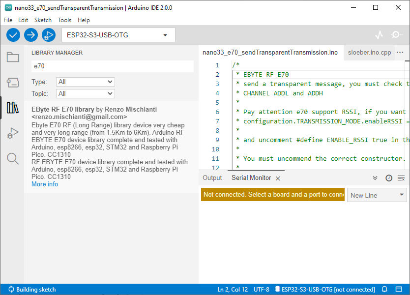
Writing the Sketch
The library offers a lot of examples, and you must only uncomment the correct constructor.
/*
 * EByte RF E70
 * send a transparent message, you must check that the transmitter and receiver have the same
 * CHANNEL ADDL and ADDH
 *
 * You must uncommend the correct constructor.
 *
 * by Renzo Mischianti <https://www.mischianti.org>
 *
 * https://www.mischianti.org
 *
 * E70		  ----- WeMos D1 mini	----- esp32			----- Arduino Nano 33 IoT	----- Arduino MKR	----- Raspberry Pi Pico   ----- stm32               ----- ArduinoUNO
 * M0         ----- D6 				----- 19 			----- 4 					----- 2 			----- 9 			      ----- PB0 		       	----- 8 Volt div
 * M1         ----- D7 				----- 21 			----- 5 					----- 3 			----- 10 			      ----- PB1 		       	----- 7 Volt div
 * M1         ----- D8 				----- 22 			----- 6 					----- 4 			----- 11 			      ----- PB10 		      	----- 6 Volt div
 * TX         ----- D3 (PullUP)		----- RX2 (PullUP)	----- RX1 (PullUP)			----- 14 (PullUP)	----- 8 (PullUP)	      ----- PA2 RX2 (PullUP)    ----- 4 (PullUP)
 * RX         ----- D4 (PullUP)		----- TX2 (PullUP)	----- TX1 (PullUP)			----- 13 (PullUP)	----- 9 (PullUP)	      ----- PA3 TX2 (PullUP)    ----- 5 Volt div (PullUP)
 * AUX        ----- D5 (PullUP)		----- 15  (PullUP)	----- 2  (PullUP)			----- 0  (PullUP)	----- 2  (PullUP)	      ----- PA0  (PullUP)       ----- 3 (PullUP)
 * VCC        ----- 3.3v/5v			----- 3.3v/5v		----- 3.3v/5v				----- 3.3v/5v		----- 3.3v/5v		      ----- 3.3v/5v             ----- 3.3v/5v
 * GND        ----- GND				----- GND			----- GND					----- GND			----- GND			      ----- GND                 ----- GND
 *
 *	Sub-packet can be emulated by set
 *	M0 = LOW
 *	M1 = HIGH
 *	M2 = LOW
 *	Continuous
 *	M0 = HIGH
 *	M1 = LOW
 *	M2 = LOW
 *
 */

#include "Arduino.h"
#include "RF_E70.h"

// ---------- esp8266 pins --------------
//RF_E70 e70ttl(RX, TX, AUX, M0, M1, M2);  // Arduino RX <-- e70 TX, Arduino TX --> e70 RX
//RF_E70 e70ttl(D3, D4, D5, D7, D6, D7); // Arduino RX <-- e70 TX, Arduino TX --> e70 RX AUX M0 M1
//RF_E70 e70ttl(D2, D3); // Config without connect AUX and M0 M1

//#include <SoftwareSerial.h>
//SoftwareSerial mySerial(D2, D3); // Arduino RX <-- e70 TX, Arduino TX --> e70 RX
//RF_E70 e70ttl(&mySerial, D5, D6, D7, D8); // AUX M0 M1
// -------------------------------------

// ---------- Arduino pins --------------
//RF_E70 e70ttl(4, 5, 3, 8, 7, 6); // Arduino RX <-- e70 TX, Arduino TX --> e70 RX AUX M0 M1
//RF_E70 e70ttl(4, 5); // Config without connect AUX and M0 M1

//#include <SoftwareSerial.h>
//SoftwareSerial mySerial(4, 5); // Arduino RX <-- e70 TX, Arduino TX --> e70 RX
//RF_E70 e70ttl(&mySerial, 3, 8, 7, 6); // AUX M0 M1
// -------------------------------------

// ------------- Arduino Nano 33 IoT -------------
// RF_E70 e70ttl(&Serial1, 2, 4, 5, 6); //  RX AUX M0 M1
// -------------------------------------------------

// ------------- Arduino MKR WiFi 1010 -------------
// RF_E70 e70ttl(&Serial1, 0, 2, 3, 4); //  RX AUX M0 M1
// -------------------------------------------------

// ---------- esp32c3 pins --------------
// RF_E70 e70ttl(&Serial1,  1, 2, 3, 4,); //  RX AUX M0 M1

// RF_E70 e70ttl(4, 5, &Serial1, 6, 1, 2, 3, UART_BPS_RATE_9600); //  esp32 RX <-- e70 TX, esp32 TX --> e70 RX AUX M0 M1
// -------------------------------------

// ---------- esp32 pins --------------
RF_E70 e70ttl(&Serial2, 15, 19, 21, 22); //  RX AUX M0 M1

//RF_E70 e70ttl(&Serial2, 22, 4, 18, 21, 19, UART_BPS_RATE_9600); //  esp32 RX <-- e70 TX, esp32 TX --> e70 RX AUX M0 M1
// -------------------------------------

// ---------- Raspberry PI Pico pins --------------
// RF_E70 e70ttl(&Serial2, 2, 10, 11, 12); //  RX AUX M0 M1
// -------------------------------------

// ---------------- STM32 --------------------
// HardwareSerial Serial2(USART2);   // PA3  (RX)  PA2  (TX)
// RF_E70 e70ttl(&Serial2, PA0, PB0, PB1, PB10); //  RX AUX M0 M1
// -------------------------------------------------

 void setup() {
  Serial.begin(9600);
#if defined(ARDUINO_ARCH_STM32) || defined(__STM32F1__) || defined(__STM32F4__)
	Serial.dtr(false);
#endif

  delay(500);

  // Startup all pins and UART
  e70ttl.begin();

//  e70ttl.setMode(MODE_CONTINUOUS_1);

//  If you have ever change configuration you must restore It

  Serial.println("Hi, I'm going to send message!");
  // Send message
  ResponseStatus rs = e70ttl.sendMessage("Hello, world?");
  // Check If there is some problem of succesfully send
  Serial.println(rs.getResponseDescription());
}

void loop() {
	// If something available
  if (e70ttl.available()>1) {
	  // read the String message
	ResponseContainer rc = e70ttl.receiveMessage();
	// Is something goes wrong print error
	if (rc.status.code!=1){
		Serial.println(rc.status.getResponseDescription());
	}else{
		// Print the data received
		Serial.println(rc.status.getResponseDescription());
		Serial.println(rc.data);
	}
  }
  if (Serial.available()) {
	  String input = Serial.readString();
	  e70ttl.sendMessage(input);
  }
}
Uploading the Sketch
Before uploading the sketch to your ESP32 device, make sure you have selected the correct board and port in the Arduino IDE. Then, click on the “Upload” button to compile and upload the sketch.
Once the upload is complete, open the Serial Monitor by going to “Tools” > “Serial Monitor” or by pressing “Ctrl+Shift+M”. Set the baud rate to 9600 and you should see the received data from the EByte E70 module being displayed in the Serial Monitor.
Thanks
I hope you have successfully connected the EByte E70 to your ESP32, ESP32C3, or ESP32 S3 device.
- EByte RF E70 433/868/900 T14S2: pinout, datasheet and specs (1.5Km)
- EByte RF E70 Module Adapter: PCB, 3D Printed, Breadboard-Friendly Solution and configuration
- Connecting the EByte E70 to ESP32 c3/s3 devices and a simple sketch example
- Connecting the EByte E70 to Arduino SAMD (Nano 33, MKR…) devices and a simple sketch example