ESP32-C3: pinout, specs and Arduino IDE configuration
The ESP32-C3 is a recent addition to the ESP32 series of microcontrollers, which includes the popular ESP32 and the more powerful ESP32-S3. While these microcontrollers share some similarities, the ESP32-C3 offers a few key advantages that make it an attractive choice for certain applications.
One of the main advantages of the ESP32-C3 is its low power consumption. The microcontroller is designed to operate at extremely low power levels, making it an ideal choice for battery-powered devices or other applications where power efficiency is critical. Additionally, the ESP32-C3 is equipped with a built-in DC-DC converter that allows it to operate from a wide range of input voltages, further expanding its versatility.
Another advantage of the ESP32-C3 is its compact size. Measuring just 5mm x 5mm, the microcontroller is significantly smaller than the ESP32 and ESP32-S3. This makes it an excellent choice for applications where space is limited, such as wearable devices or IoT sensors.
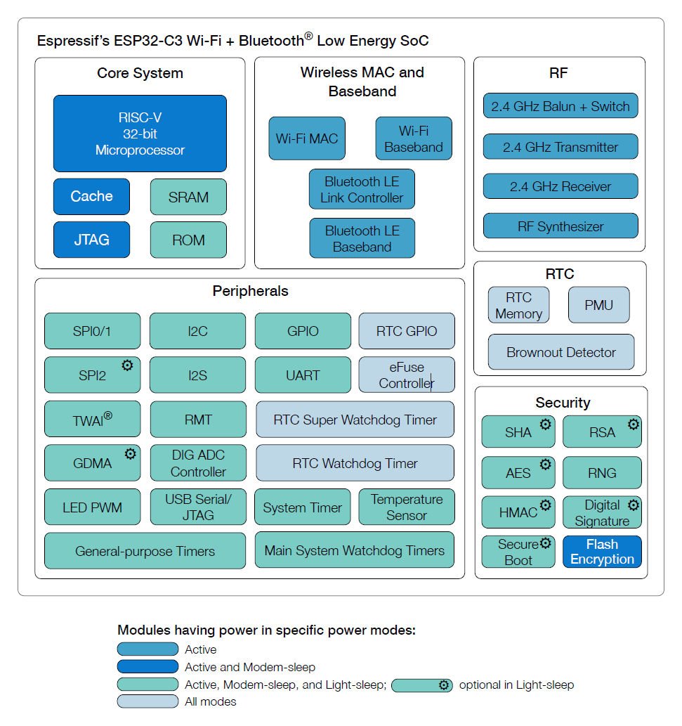
Despite its smaller size and lower power consumption, the ESP32-C3 still offers impressive performance. The microcontroller is based on the RISC-V architecture and features a single-core 32-bit CPU that can run at speeds up to 160 MHz. It also includes a variety of peripherals, including UART, I2C, SPI, and I2S interfaces, as well as support for Wi-Fi and Bluetooth connectivity.
Overall, the ESP32-C3 is a versatile and powerful microcontroller that offers several advantages over its predecessors, particularly in terms of power consumption and size. While the ESP32 and ESP32-S3 may be better suited for certain applications, the ESP32-C3 is an excellent choice for anyone looking to build a low-power, compact device with robust wireless connectivity.
Here my devices selection LuatOS esp32c3 Core - ESP32-C3-DevKitC-02 - ESP32-C3-MINI-1 - WeMos LOLIN C3 PICO - WeMos LOLIN C3 Mini v2.1 - WeMos LOLIN C3 Mini v1.0 - ESP32 S3 Purlple AI-S3
Specs
Remember that exist a lot of variants of this device, some have a specified killer function, so this is a generic specs description.
CPU and Memory
- 32-bit RISC-V single-core processor, up to 160
MHz - CoreMark® score:
- 1 core at 160 MHz: 407.22 CoreMark; 2.55
CoreMark/MHz
- 1 core at 160 MHz: 407.22 CoreMark; 2.55
- 384 KB ROM
- 400 KB SRAM (16 KB for cache)
- 8 KB SRAM in RTC
- Embedded flash (see details in Chapter 1
ESP32-C3 Series Comparison) - SPI, Dual SPI, Quad SPI, and QPI interfaces that
allow connection to multiple external flash - Access to flash accelerated by cache
- Supports flash in-Circuit Programming (ICP)
| Ordering Code | Embedded Flash | Ambient Temperature (°C) | Package (mm) | GPIO No. |
|---|---|---|---|---|
| ESP32-C3 | No | –40 ∼ 105 | QFN32 (5*5) | 22 |
| ESP32-C3FN4 | 4 MB | –40 ∼ 85 | QFN32 (5*5) | 22 |
| ESP32-C3FH4 | 4 MB | –40 ∼ 105 | QFN32 (5*5) | 22 |
| ESP32-C3FH4AZ | 4 MB | –40 ∼ 105 | QFN32 (5*5) | 16 |
Advanced Peripheral Interfaces
- 22 or 16 programmable GPIOs
- Digital interfaces:
- 3 × SPI
- 2 × UART
- 1 × I2C
- 1 × I2S
- Remote control peripheral, with 2 transmit
channels and 2 receive channels - LED PWM controller, with up to 6 channels
- Full-speed USB Serial/JTAG controller
- General DMA controller (GDMA), with 3
transmit channels and 3 receive channels - 1 × TWAI® controller compatible with ISO
11898-1 (CAN Specification 2.0)
- Analog interfaces:
- 2 × 12-bit SAR ADCs, up to 6 channels
- 1 × temperature sensor
- Timers:
- 2 × 54-bit general-purpose timers
- 3 × digital watchdog timers
- 1 × analog watchdog timer
- 1 × 52-bit system timer
WiFi
- IEEE 802.11 b/g/n-compliant
- Supports 20 MHz, 40 MHz bandwidth in 2.4
GHz band - 1T1R mode with data rate up to 150 Mbps
- 4 × virtual Wi-Fi interfaces
- 802.11mc FTM
Bluetooth
- Bluetooth LE: Bluetooth 5, Bluetooth mesh
- High power mode (21 dBm)
- Speed: 125 Kbps, 500 Kbps, 1 Mbps, 2 Mbps
- Advertising extensions
- Multiple advertisement sets
- Channel selection algorithm #2
- Internal co-existence mechanism between Wi-Fi
and Bluetooth to share the same antenna
Security
- Secure boot
- Flash encryption
- 4096-bit OTP, up to 1792 bits for use
- Cryptographic hardware acceleration:
- AES-128/256 (FIPS PUB 197)
- Permission Control
- SHA Accelerator (FIPS PUB 180-4)
- RSA Accelerator
- Random Number Generator (RNG)
- HMAC
- Digital signature
Low Power Management
- Power Management Unit with four power modes
Pinouts
The pinout of the ESP32-C3 is organized into several different groups, each with its own specific functions.
The first group of pins is the power supply pins, which include VDD and GND. VDD is the power input pin, which can accept voltages between 1.8V and 3.6V. The GND pin is the ground reference for the microcontroller.
The second group of pins is the GPIO (General Purpose Input/Output) pins. These pins can be used for a wide range of applications, such as controlling LEDs, reading switches, and interfacing with sensors. There are a total of 19 GPIO pins on the ESP32-C3, each of which can be configured as either an input or output.
The third group of pins is the analog input pins. These pins can be used to read analog signals, such as those from sensors or potentiometers. There are a total of 4 analog input pins on the ESP32-C3.
In addition to these groups, the ESP32-C3 also includes several other pins for specific functions. These include the UART pins, which can be used for serial communication with other devices, the SPI pins, which can be used for high-speed communication with other devices, and the I2C pins, which can be used for communicating with sensors and other devices that use the I2C protocol.
ESP32-C3 DevKitC 02
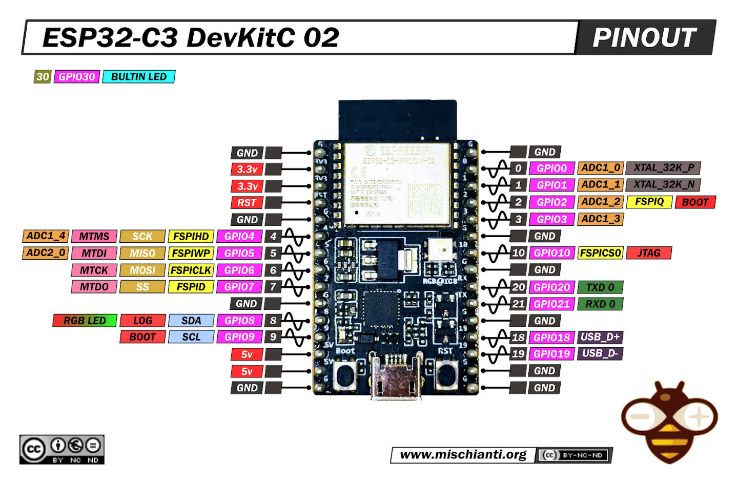
ESP32-C3-DevKitC-02: high-resolution pinout and specs
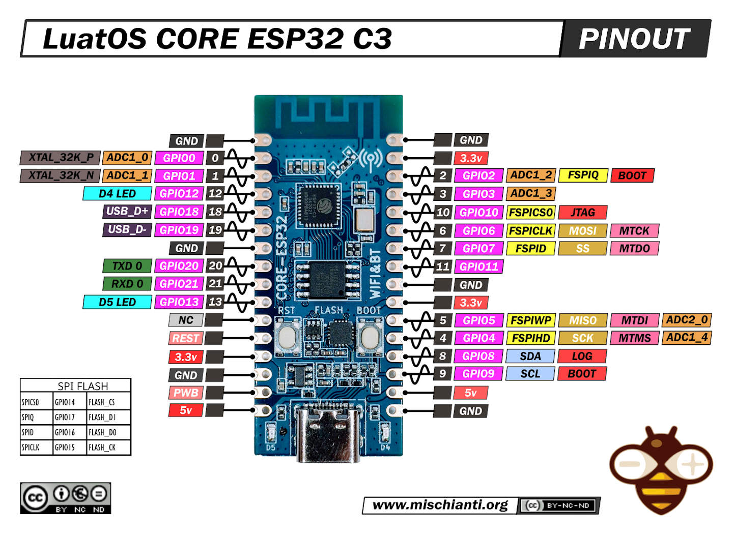
LuatOS CORE ESP32 C3: high-resolution pinout and specs
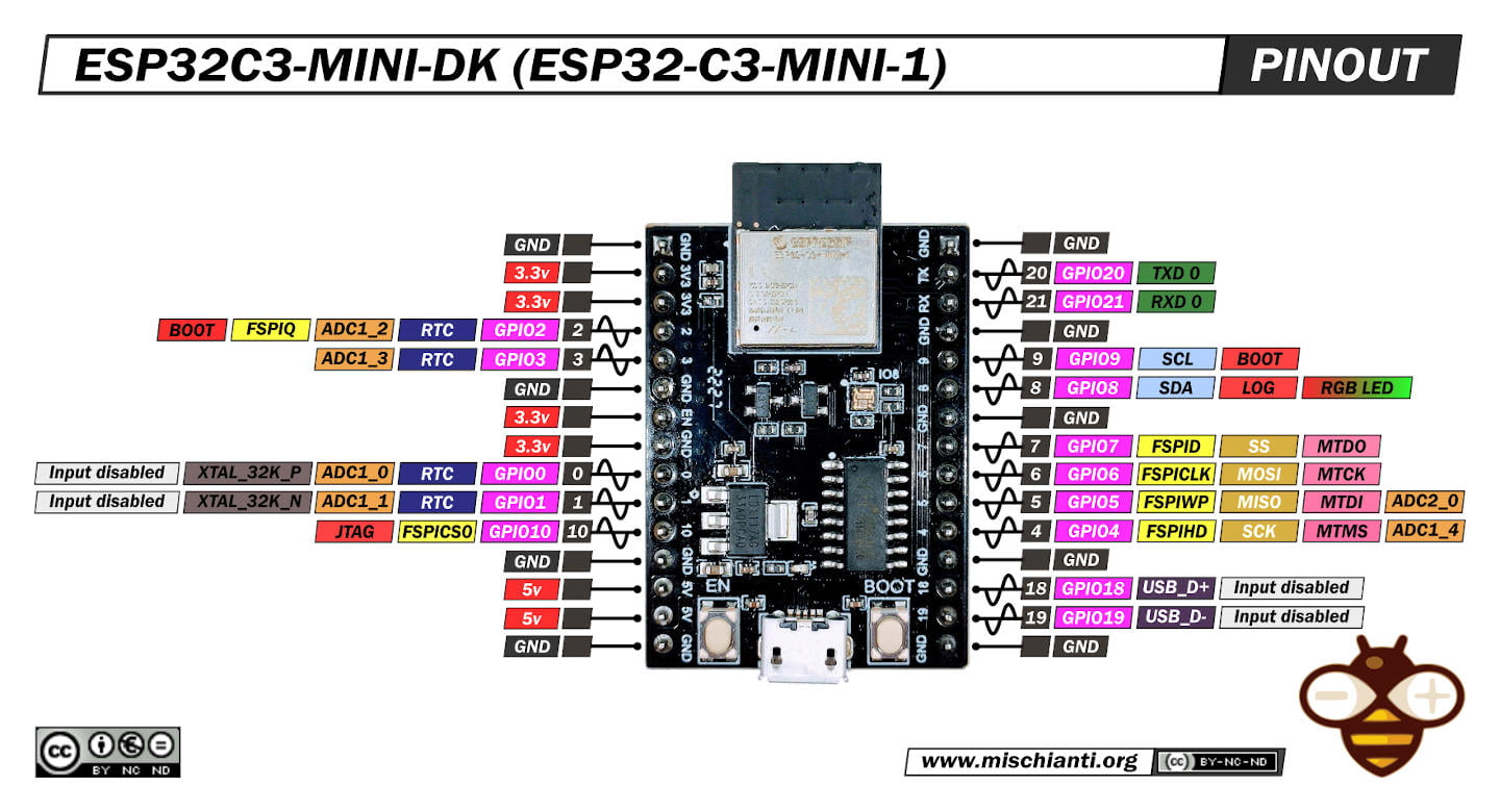
ESP32C3-MINI-DK: high-resolution pinout and specs
How to
You must download drivers for the USB chips, probably you have an esp32 version with cp2102, but exist a variant with ch340 chip.
Then you must configure your Arduino IDE
Add the boards to Arduino IDE 1.x
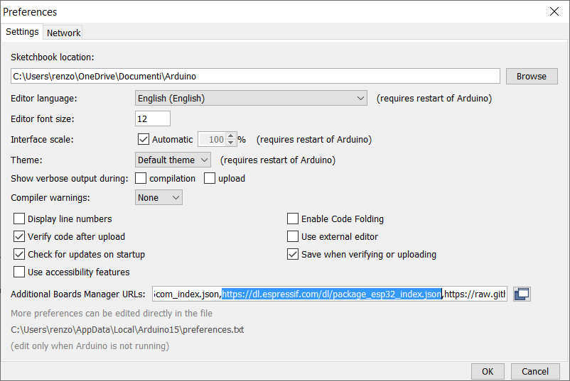
First, you must add the esp32 URL descriptor to your IDE
https://dl.espressif.com/dl/package_esp32_index.json
Go to File --> Preferences and add the URL on “Additional Boards Manager URLs“
Then you must add a new board in the Boards Manager
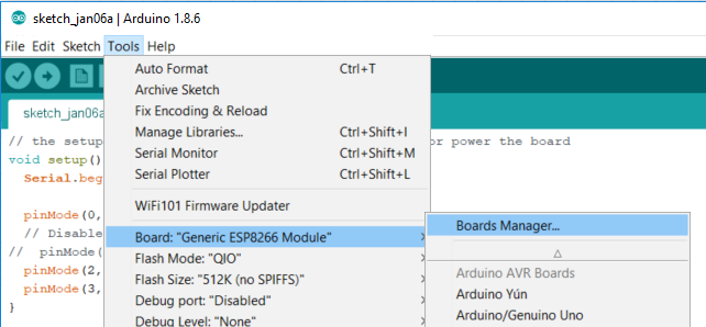
The boards to select are esp32
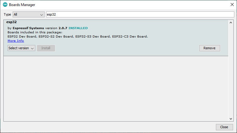
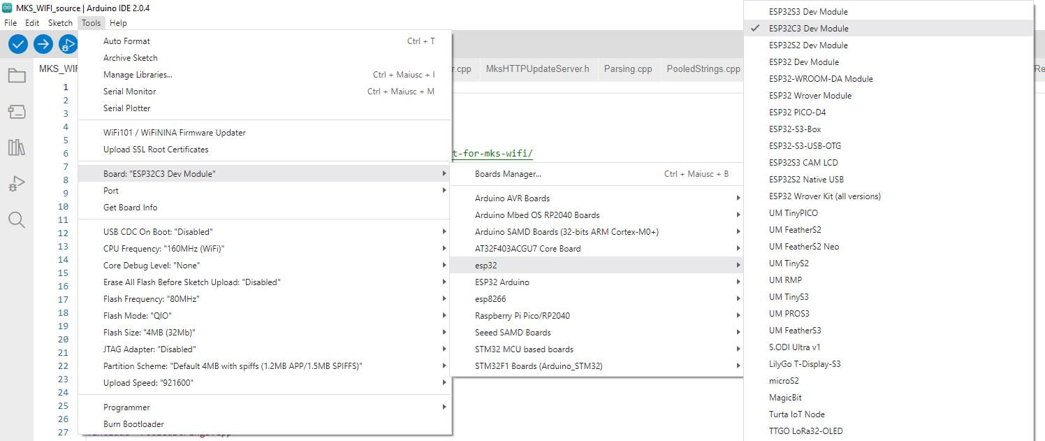
Select the board
Select (if you have, like me, that model) the ESP32c3 Dev Module
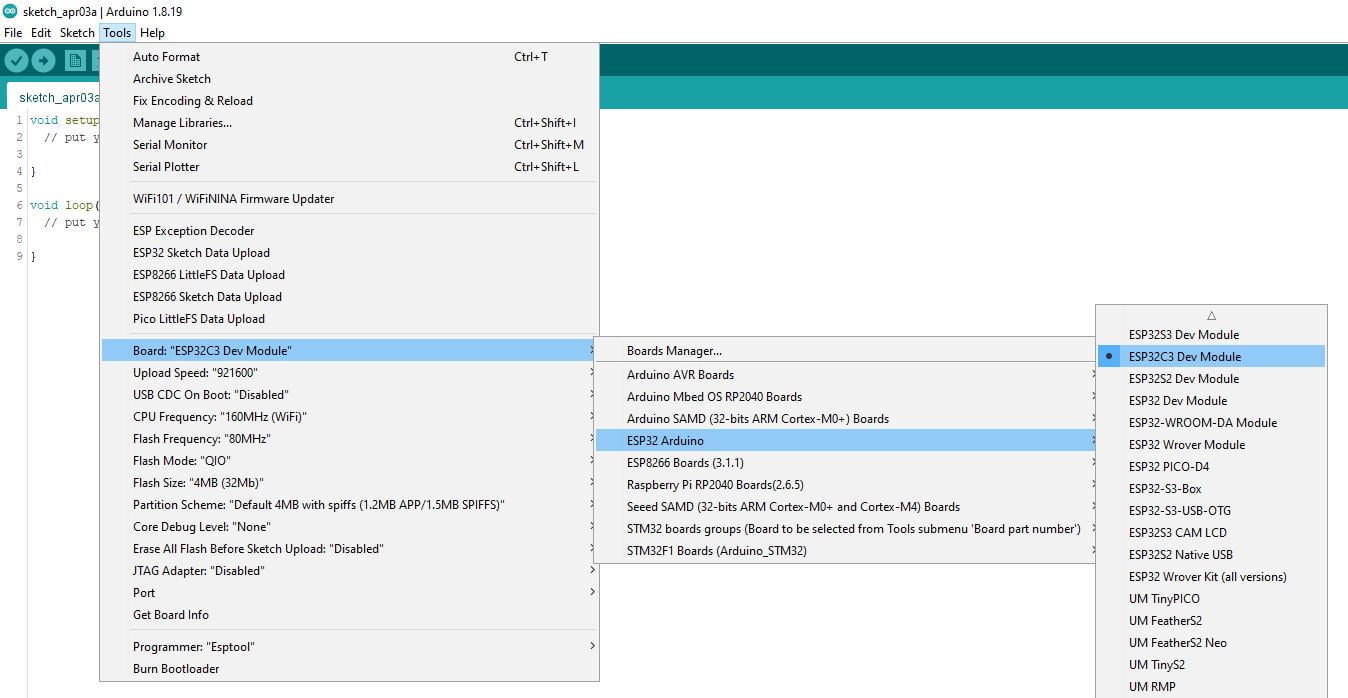
Now you can upload your sketch.
Add the boards to Arduino IDE 2.x
First, you must add the esp32 URL descriptor to your IDE
https://dl.espressif.com/dl/package_esp32_index.json
Go to File --> Preferences and add the URL on “Additional Boards Manager URLs”
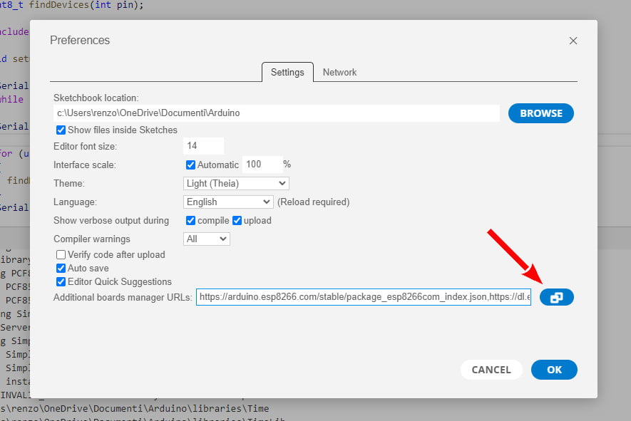
Now you can add the boards’ descriptor to your IDE.
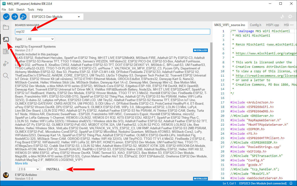
Select the board
Now your IDE support esp32 boards, so you can find the specified board.
Examples
Here we will delve into a series of hands-on examples that will only help you familiarize yourself with the capabilities of the ESP32-C3.
Blink examples
Not all devices illustrated in the previous section can do the blink sketch. For example, the ESP32-C3-DevKitC-02 can do the blink sketch by using pin 30.
int led = LED_BUILTIN;

void setup() {
	pinMode(LED_BUILTIN, OUTPUT);
}

void loop() {
	digitalWrite(LED_BUILTIN, HIGH); // turn the LED on (HIGH is the voltage level)
	delay(500); // wait for a half second
	digitalWrite(LED_BUILTIN, LOW); // turn the LED off by making the voltage LOW
	delay(500); // wait for a half second
}
In this case, LED_BUILTIN point to pin 30, but to use RGB led, you must go straight to pin 8.
For LuatOS CORE-ESP32 you can try this sketch that blinks the 2 LEDs on the board.
Pay attention; you must use DIO Flash mode otherwise, nothing works.
With LuatOS you must use Flash mode: DIO
int LED_BUILTIN_D4 = 12;
int LED_BUILTIN_D5 = 13;

void setup() {
// Some boards work best if we also make a serial connection
	Serial.begin(115200);

	// set LED to be an output pin
	pinMode(LED_BUILTIN_D4, OUTPUT);
	pinMode(LED_BUILTIN_D5, OUTPUT);
}

void loop() {
	digitalWrite(LED_BUILTIN_D4, HIGH); // turn the LED on (HIGH is the voltage level)
	digitalWrite(LED_BUILTIN_D5, LOW); // turn the LED on (HIGH is the voltage level)
	delay(100); // wait for a half second

	digitalWrite(LED_BUILTIN_D4, LOW); // turn the LED off by making the voltage LOW
	digitalWrite(LED_BUILTIN_D5, HIGH); // turn the LED off by making the voltage LOW
	delay(100); // wait for a half second
}
Thanks
- ESP32: pinout, specs and Arduino IDE configuration
- ESP32: integrated SPIFFS Filesystem
- ESP32: manage multiple Serial and logging
- ESP32 practical power saving
- ESP32 practical power saving: manage WiFi and CPU
- ESP32 practical power saving: modem and light sleep
- ESP32 practical power saving: deep sleep and hibernation
- ESP32 practical power saving: preserve data, timer and touch wake up
- ESP32 practical power saving: external and ULP wake up
- ESP32 practical power saving: UART and GPIO wake up
- ESP32: integrated LittleFS FileSystem
- ESP32: integrated FFat (Fat/exFAT) FileSystem
- ESP32-wroom-32
- ESP32-CAM
- ESP32: use ethernet w5500 with plain (HTTP) and SSL (HTTPS)
- ESP32: use ethernet enc28j60 with plain (HTTP) and SSL (HTTPS)
- How to use SD card with esp32
- esp32 and esp8266: FAT filesystem on external SPI flash memory
- Firmware and OTA update management
- Firmware management
- OTA update with Arduino IDE
- OTA update with Web Browser
- Self OTA uptate from HTTP server
- Non-standard Firmware update
- Integrating LAN8720 with ESP32 for Ethernet Connectivity with plain (HTTP) and SSL (HTTPS)
- Connecting the EByte E70 to ESP32 c3/s3 devices and a simple sketch example
- ESP32-C3: pinout, specs and Arduino IDE configuration
- Integrating W5500 with ESP32 Using Core 3: Native Ethernet Protocol Support with SSL and Other Features
- Integrating LAN8720 with ESP32 Using Core 3: Native Ethernet Protocol Support with SSL and Other Features
- Dallas ds18b20:
- Guide to I2C on ESP32: Communication with Heterogeneous 5V and 3.3V Devices, Additional Interface Management and Scanner
- Display
- Complete Guide: Using an ILI9341 Display with the TFT_eSPI Library
- Integrating Touch Screen Functionality with Your ILI9341 TFT Display
- SSD1683 eInk Display with GxEPD and ESP32 (and CrowPanel 4.2″ HMI): basics and configuration