
ESP32 practical power saving: store data, timer and touch wake up – 4
With the esp32, when using light sleep, deep sleep, or hibernation, you need to select the wake-up source to turn the device back on.
There are many solutions, and some are the standard RTC or external. Others are new entries like touch or ULP.
Suppose you have already read the previous chapter. In that case, you know that there are significant differences in power consumption if you select an external or timer to wake up the source, so pay attention to your choice.
But (and now you think I’m boring) you also need to pay attention to the type of sleep mode you use because light sleep has more varieties of wake-up sources than others and can come in handy.
Storing value across deep sleep and load code after wake
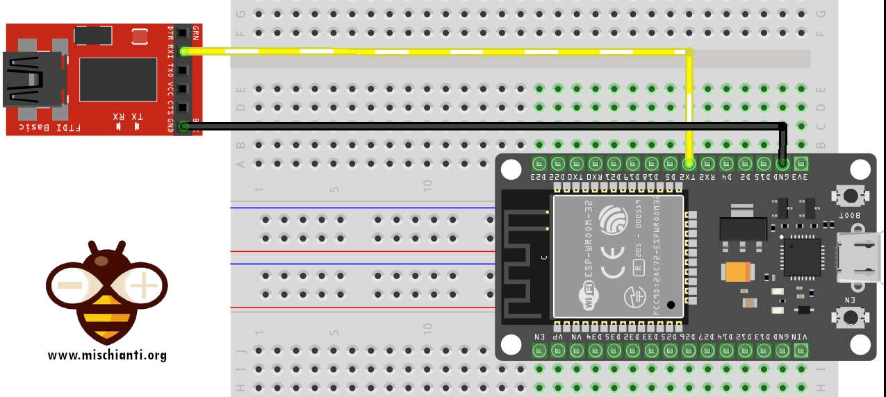
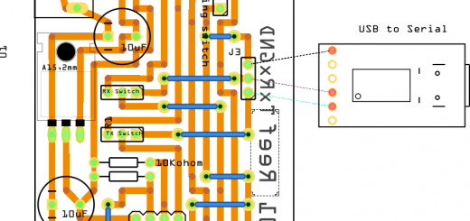
I use the Serial2 to debug; you can find more information in this article “ESP32: manage multiple Serial and logging for debugging“.
Here is the connection schema to use external FDTI on Serial2.
The wake stub code must be resident in RTC Fast Memory. Develop can do this in one of two ways.
The first way is to use the RTC_IRAM_ATTR attribute to place a function into RTC memory:
void RTC_IRAM_ATTR esp_wake_deep_sleep(void) {
    esp_default_wake_deep_sleep();
    // Add additional functionality here
}
The second way is to place the function into any source file whose name starts with rtc_wake_stub. Files names rtc_wake_stub* have their contents automatically put into RTC memory by the linker.
Storing data during deep sleep can be done in two ways, but the simplest is to use RTC_DATA_ATTR and RTC_RODATA_ATTR to specify all data (writable or read-only, respectively) that should be loaded into RTC memory:
// preserve data
RTC_DATA_ATTR int wake_count;

void RTC_IRAM_ATTR esp_wake_deep_sleep(void) {
    esp_default_wake_deep_sleep();
    // increment data after wake
    wake_count++;
}
Here is a complete sketch to verify its behavior
/*
 *  ESP32
 *  Variable behaivor in DEEP Sleep
 *  by Mischianti Renzo <https://mischianti.org>
 *
 *  https://mischianti.org/esp32-practical-power-saving-store-data-timer-and-touch-wake-up-4/
 *
 */
#include "Arduino.h"

// Preserved value
RTC_DATA_ATTR int wake_count = 0;
RTC_DATA_ATTR int wake_count2 = 0;
// Not preserved
int wake_count3 = 0;

// Call function every wake
void RTC_IRAM_ATTR esp_wake_deep_sleep(void) {
    esp_default_wake_deep_sleep();
    // increment every wake
    wake_count2++;
}

void setup()
{
	  ++wake_count;
	  ++wake_count3;

	Serial2.begin(115200);

	while(!Serial2){delay(500);}

	Serial2.println("Wake count in setup: " + String(wake_count));
	Serial2.println("Wake count2 in setup: " + String(wake_count2));
	Serial2.println("Wake count3 in setup: " + String(wake_count3));

    Serial2.println();
    Serial2.println("DEEP SLEEP ENABLED FOR 5secs");
    delay(100);

    esp_sleep_enable_timer_wakeup(5 * 1000 * 1000);

    esp_deep_sleep_start();

    Serial2.println();
    Serial2.println("DEEP SLEEP WAKE UP");
}

void loop()
{

}
Here is the Serial2 result:
Wake count in setup: 1
Wake count2 in setup: 0
Wake count3 in setup: 1

DEEP SLEEP ENABLED FOR 5secs
Wake count in setup: 2
Wake count2 in setup: 1
Wake count3 in setup: 1

DEEP SLEEP ENABLED FOR 5secs
Wake count in setup: 3
Wake count2 in setup: 2
Wake count3 in setup: 1

DEEP SLEEP ENABLED FOR 5secs
Wake count in setup: 4
Wake count2 in setup: 3
Wake count3 in setup: 1

DEEP SLEEP ENABLED FOR 5secs
Wake types
You can have some information when the sketch restart from a deep sleep, the first in the wake-up source, and you can check that with these commands
/*
Method to print the reason by which ESP32
has been awaken from sleep
*/
void print_wakeup_reason(){
  esp_sleep_wakeup_cause_t wakeup_reason;

  wakeup_reason = esp_sleep_get_wakeup_cause();

  switch(wakeup_reason)
  {
    case ESP_SLEEP_WAKEUP_EXT0 : Serial2.println("Wakeup caused by external signal using RTC_IO"); break;
    case ESP_SLEEP_WAKEUP_EXT1 : Serial2.println("Wakeup caused by external signal using RTC_CNTL"); break;
    case ESP_SLEEP_WAKEUP_TIMER : Serial2.println("Wakeup caused by timer"); break;
    case ESP_SLEEP_WAKEUP_TOUCHPAD : Serial2.println("Wakeup caused by touchpad"); break;
    case ESP_SLEEP_WAKEUP_ULP : Serial2.println("Wakeup caused by ULP program"); break;
    default : Serial2.printf("Wakeup was not caused by deep sleep: %d\n",wakeup_reason); break;
  }
}
And when you select a particular wake-up source, you probably have a command to retrieve other information, but we will check that soon.
Timer
RTC controller has a built-in timer that It can use to wake up the chip after a predefined amount of time. Time is specified at microsecond precision, but the resolution depends on the clock source selected for RTC SLOW_CLK.
This wake-up mode doesn’t require RTC peripherals or RTC memories to be powered on during sleep (check the previous article to understand the benefit).
esp_err_tesp_sleep_enable_timer_wakeup(uint64_t time_in_us)
Enable wake-up by timer.
Return
ESP_OKon successESP_ERR_INVALID_ARGif value is out of range
Parameters
time_in_us: time before wakeup, in microseconds (time_in_us * 1000 = milliseconds * 1000 = seconds)
Here is the complete sketch:
/*
 *  ESP32
 *  DEEP Sleep and timer wake up
 *  by Mischianti Renzo <https://mischianti.org>
 *
 *  https://mischianti.org/esp32-practical-power-saving-store-data-timer-and-touch-wake-up-4/
 *
 */

#define TIME_TO_SLEEP  5        	/* Time ESP32 will go to sleep (in seconds) */

RTC_DATA_ATTR int bootCount = 0;

/*
Method to print the reason by which ESP32
has been awaken from sleep
*/
void print_wakeup_reason(){
  esp_sleep_wakeup_cause_t wakeup_reason;

  wakeup_reason = esp_sleep_get_wakeup_cause();

  switch(wakeup_reason)
  {
    case ESP_SLEEP_WAKEUP_EXT0 : Serial2.println("Wakeup caused by external signal using RTC_IO"); break;
    case ESP_SLEEP_WAKEUP_EXT1 : Serial2.println("Wakeup caused by external signal using RTC_CNTL"); break;
    case ESP_SLEEP_WAKEUP_TIMER : Serial2.println("Wakeup caused by timer"); break;
    case ESP_SLEEP_WAKEUP_TOUCHPAD : Serial2.println("Wakeup caused by touchpad"); break;
    case ESP_SLEEP_WAKEUP_ULP : Serial2.println("Wakeup caused by ULP program"); break;
    default : Serial2.printf("Wakeup was not caused by deep sleep: %d\n",wakeup_reason); break;
  }
}

void setup(){
  Serial2.begin(115200);
  delay(1000); //Take some time to open up the Serial Monitor

  //Increment boot number and print it every reboot
  ++bootCount;
  Serial2.println("Boot number: " + String(bootCount));

  //Print the wakeup reason for ESP32
  print_wakeup_reason();

  /*
  First we configure the wake up source
  We set our ESP32 to wake up every 5 seconds
  */
  esp_sleep_enable_timer_wakeup(TIME_TO_SLEEP * 1000 * 1000);
  Serial2.println("Setup ESP32 to sleep for every " + String(TIME_TO_SLEEP) +
  " Seconds");

  Serial2.println("Going to sleep now");
  Serial2.flush();
  esp_deep_sleep_start();
  Serial2.println("This will never be printed");
}

void loop(){
  //This is not going to be called
}
The result is:
Boot number: 1
Wakeup was not caused by deep sleep: 0
Setup ESP32 to sleep for every 5 Seconds
Going to sleep now
Boot number: 2
Wakeup caused by timer
Setup ESP32 to sleep for every 5 Seconds
Going to sleep now
Boot number: 3
Touch
RTC IO module contains logic to trigger wake-up when a touch sensor interrupt occurs. You need to configure the touchpad interrupt before the chip starts deep sleep.
Revisions 0 and 1 of the ESP32 only support this wake-up mode when RTC peripherals are not forced to be powered on.
esp_err_t esp_deep_sleep_enable_touchpad_wakeup()
Enable the wake-up touch sensor.
Note: in revisions 0 and 1 of the ESP32, the touch wake-up source can not be used when the RTC_PERIPH power domain is forced to be powered on (ESP_PD_OPTION_ON) or when the ext0 wake-up source is used.
Return
ESP_OKon successESP_ERR_INVALID_STATEif wakeup triggers conflict
And there is a function to set the correct wake-up touch pin
void touchAttachInterrupt(uint8_t pin, void (*userFunc)(void), uint16_t threshold);
Select the correct touch pin and define the callback and threshold.
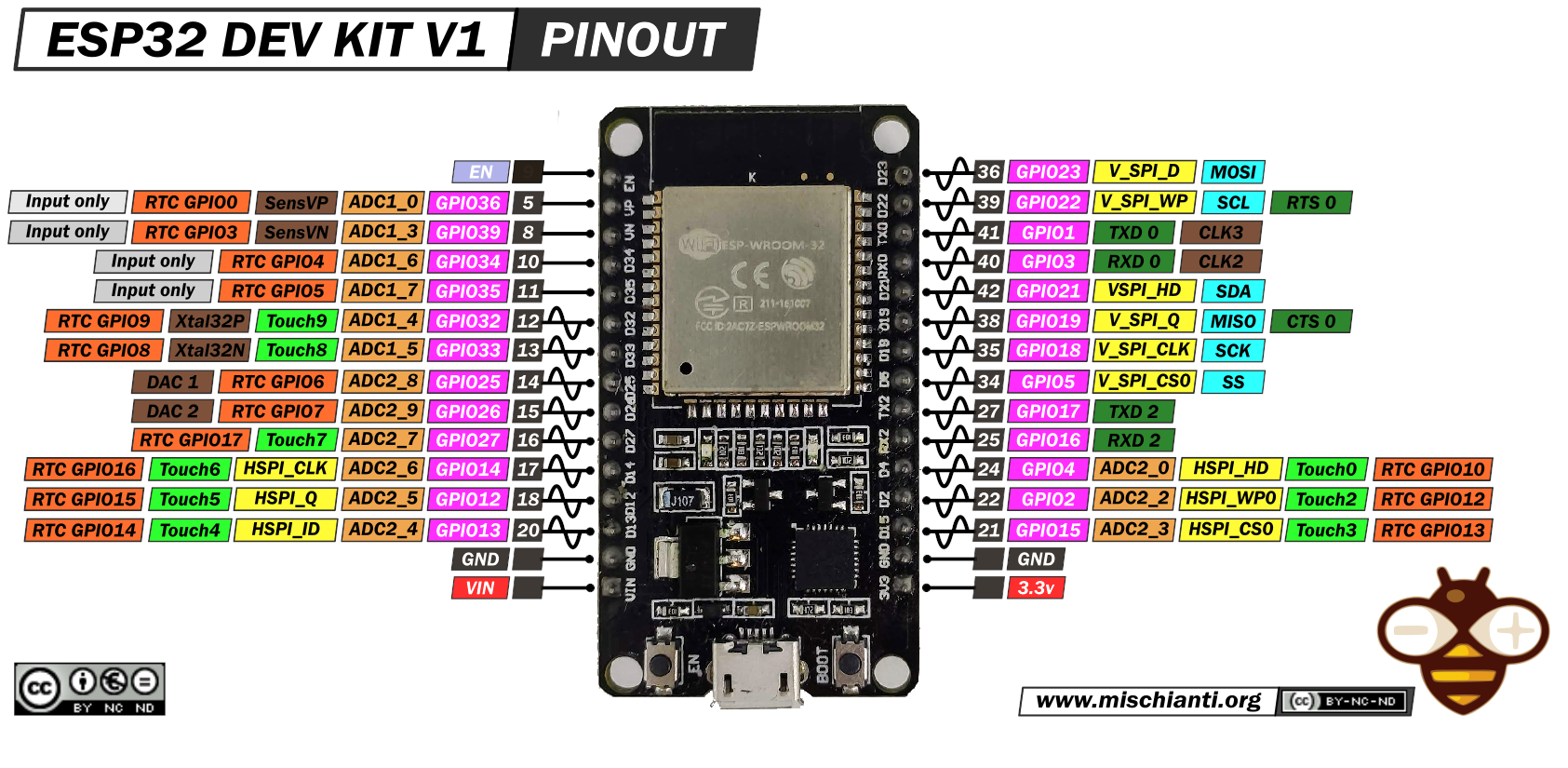
For more information on the device, refer to “DOIT ESP32 DEV KIT v1 high resolution pinout and specs“.
Here is the code of touch pins.
T0: GPIO 4T1: GPIO 0T2: GPIO 2T3: GPIO 15T4: GPIO 13T5: GPIO 12T6: GPIO 14T7: GPIO 27T8: GPIO 33T9: GPIO 32
There is a command to check which pins have been touched
/*
Method to print the touchpad by which ESP32
has been awaken from sleep
*/
void print_wakeup_touchpad(){
  touchPin = esp_sleep_get_touchpad_wakeup_status();

  switch(touchPin)
  {
    case 0  : Serial2.println("Touch detected on GPIO 4"); break;
    case 1  : Serial2.println("Touch detected on GPIO 0"); break;
    case 2  : Serial2.println("Touch detected on GPIO 2"); break;
    case 3  : Serial2.println("Touch detected on GPIO 15"); break;
    case 4  : Serial2.println("Touch detected on GPIO 13"); break;
    case 5  : Serial2.println("Touch detected on GPIO 12"); break;
    case 6  : Serial2.println("Touch detected on GPIO 14"); break;
    case 7  : Serial2.println("Touch detected on GPIO 27"); break;
    case 8  : Serial2.println("Touch detected on GPIO 33"); break;
    case 9  : Serial2.println("Touch detected on GPIO 32"); break;
    default : Serial2.println("Wakeup not by touchpad"); break;
  }
}
Very simple but very important, and now the complete sketch:
/*
* ESP32
* DEEP Sleep and touch wake up
* by Mischianti Renzo <https://mischianti.org>
*
* https://mischianti.org/esp32-practical-power-saving-store-data-timer-and-touch-wake-up-4/
*
*/
#define Threshold 60 /* Greater the value, more the sensitivity */
RTC_DATA_ATTR int bootCount = 0;
touch_pad_t touchPin;
/*
Method to print the reason by which ESP32
has been awaken from sleep
*/
void print_wakeup_reason(){
esp_sleep_wakeup_cause_t wakeup_reason;
wakeup_reason = esp_sleep_get_wakeup_cause();
switch(wakeup_reason)
{
case ESP_SLEEP_WAKEUP_EXT0 : Serial2.println("Wakeup caused by external signal using RTC_IO"); break;
case ESP_SLEEP_WAKEUP_EXT1 : Serial2.println("Wakeup caused by external signal using RTC_CNTL"); break;
case ESP_SLEEP_WAKEUP_TIMER : Serial2.println("Wakeup caused by timer"); break;
case ESP_SLEEP_WAKEUP_TOUCHPAD : Serial2.println("Wakeup caused by touchpad"); break;
case ESP_SLEEP_WAKEUP_ULP : Serial2.println("Wakeup caused by ULP program"); break;
default : Serial2.printf("Wakeup was not caused by deep sleep: %d\n",wakeup_reason); break;
}
}
/*
Method to print the touchpad by which ESP32
has been awaken from sleep
*/
void print_wakeup_touchpad(){
touchPin = esp_sleep_get_touchpad_wakeup_status();
switch(touchPin)
{
case 0 : Serial2.println("Touch detected on GPIO 4"); break;
case 1 : Serial2.println("Touch detected on GPIO 0"); break;
case 2 : Serial2.println("Touch detected on GPIO 2"); break;
case 3 : Serial2.println("Touch detected on GPIO 15"); break;
case 4 : Serial2.println("Touch detected on GPIO 13"); break;
case 5 : Serial2.println("Touch detected on GPIO 12"); break;
case 6 : Serial2.println("Touch detected on GPIO 14"); break;
case 7 : Serial2.println("Touch detected on GPIO 27"); break;
case 8 : Serial2.println("Touch detected on GPIO 33"); break;
case 9 : Serial2.println("Touch detected on GPIO 32"); break;
default : Serial2.println("Wakeup not by touchpad"); break;
}
}
void callback(){
//placeholder callback function
}
void setup(){
Serial2.begin(115200);
delay(1000); //Take some time to open up the Serial Monitor
//Increment boot number and print it every reboot
++bootCount;
Serial2.println("Boot number: " + String(bootCount));
//Print the wakeup reason for ESP32 and touchpad too
print_wakeup_reason();
print_wakeup_touchpad();
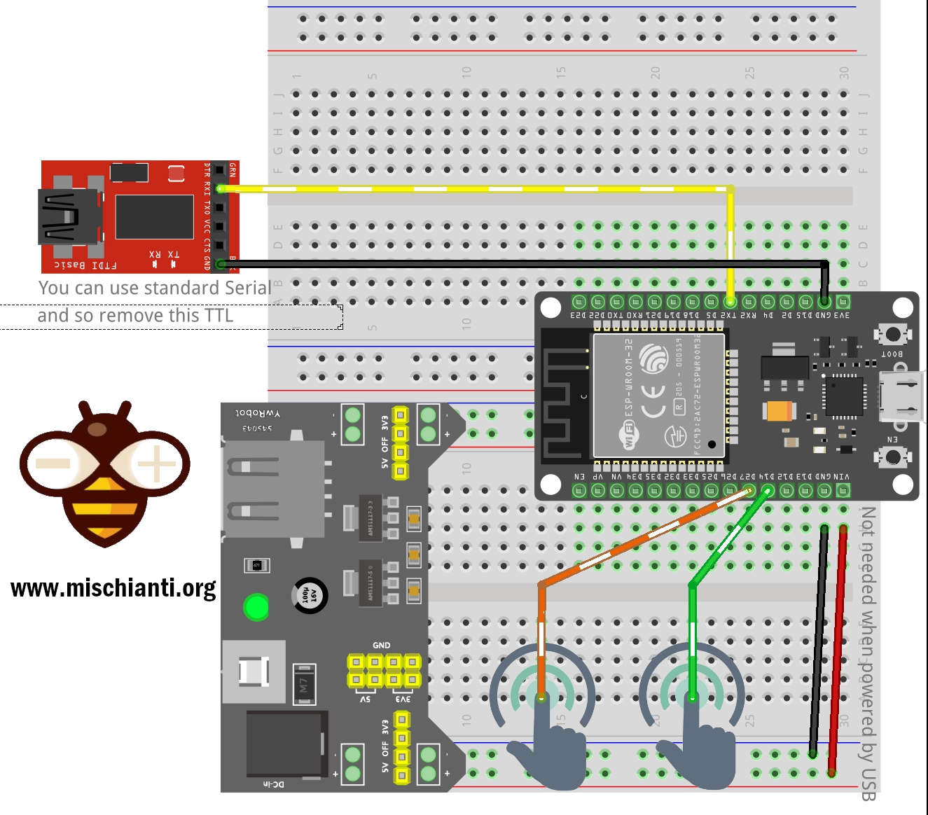
//Setup interrupt on Touch Pad 6 (GPIO14)
touchAttachInterrupt(T6, callback, Threshold);
//Setup interrupt on Touch Pad 7 (GPIO27)
touchAttachInterrupt(T7, callback, Threshold);
//Configure Touchpad as wakeup source
esp_sleep_enable_touchpad_wakeup();
//Go to sleep now
Serial2.println("Going to sleep now");
esp_deep_sleep_start();
Serial2.println("This will never be printed");
}
void loop(){
//This will never be reached
}
and here is a piece of Serial2 output:
Boot number: 3
Wakeup caused by touchpad
Touch detected on GPIO 14
Going to sleep now
Boot number: 4
Wakeup caused by touchpad
Touch detected on GPIO 27
Going to sleep now
Boot number: 5
Thanks
- ESP32: pinout, specs and Arduino IDE configuration
- ESP32: integrated SPIFFS Filesystem
- ESP32: manage multiple Serial and logging
- ESP32 practical power saving
- ESP32 practical power saving: manage WiFi and CPU
- ESP32 practical power saving: modem and light sleep
- ESP32 practical power saving: deep sleep and hibernation
- ESP32 practical power saving: preserve data, timer and touch wake up
- ESP32 practical power saving: external and ULP wake up
- ESP32 practical power saving: UART and GPIO wake up
- ESP32: integrated LittleFS FileSystem
- ESP32: integrated FFat (Fat/exFAT) FileSystem
- ESP32-wroom-32
- ESP32-CAM
- ESP32: use ethernet w5500 with plain (HTTP) and SSL (HTTPS)
- ESP32: use ethernet enc28j60 with plain (HTTP) and SSL (HTTPS)
- How to use SD card with esp32
- esp32 and esp8266: FAT filesystem on external SPI flash memory
- Firmware and OTA update management
- Firmware management
- OTA update with Arduino IDE
- OTA update with Web Browser
- Self OTA uptate from HTTP server
- Non-standard Firmware update
- Integrating LAN8720 with ESP32 for Ethernet Connectivity with plain (HTTP) and SSL (HTTPS)
- Connecting the EByte E70 to ESP32 c3/s3 devices and a simple sketch example
- ESP32-C3: pinout, specs and Arduino IDE configuration
- Integrating W5500 with ESP32 Using Core 3: Native Ethernet Protocol Support with SSL and Other Features
- Integrating LAN8720 with ESP32 Using Core 3: Native Ethernet Protocol Support with SSL and Other Features
- Dallas ds18b20:
- Guide to I2C on ESP32: Communication with Heterogeneous 5V and 3.3V Devices, Additional Interface Management and Scanner
- Display
- Complete Guide: Using an ILI9341 Display with the TFT_eSPI Library
- Integrating Touch Screen Functionality with Your ILI9341 TFT Display
- SSD1683 eInk Display with GxEPD and ESP32 (and CrowPanel 4.2″ HMI): basics and configuration


Hi Renzo. Do you have any experience with sleep / wake of the WEMO LOLIN C3 MINI ? I cant get it to wake from deep or light sleep with timer, RTC_IO or GPIO. I’m using Arduino IDE 2.0 and latest ESPRESSIF 2.0.6 board library. The data sheet says it should work. Im using code examples published by ESPRESSIF (and yours too). They work fine on ESP 32 WROOM, but not on the WEMO LOLIN C3 MINI. Any ideas? John
Hi,
no sorry, I don’t use extensively boards like Raspberry Pi Pico, esp32 s3, esp32 c3 because It’s too young and the framework not yet supported well advanced features.
Bye Renzo