ESP32 risparmio energetico pratico: preservare i dati, sveglia a tempo e tramite tocco – 4
Con l’esp32, quando si utilizza un sonno leggero, un sonno profondo o uno stato di ibernazione, è necessario selezionare la sorgente di risveglio per far tornare attivo il dispositivo.
Ci sono molte soluzioni, alcune sono standard RTC o esterne, altre sono new entry come touch o ULP.
Se hai già letto il capitolo precedente, sai che ci sono alcune grandi differenze nel consumo di energia se selezioni una fonte di sveglia esterna o timer, quindi fai attenzione alla tua scelta.
Ma (e ora pensi che io sia noioso) devi prestare attenzione anche al tipo di modalità di sonno che usi, perché il sonno leggero ha più tipi di risveglio rispetto alle altre e può tornarti utile.
Conservare i dati durante la sospensione profonda e caricare del codice dopo la riattivazione
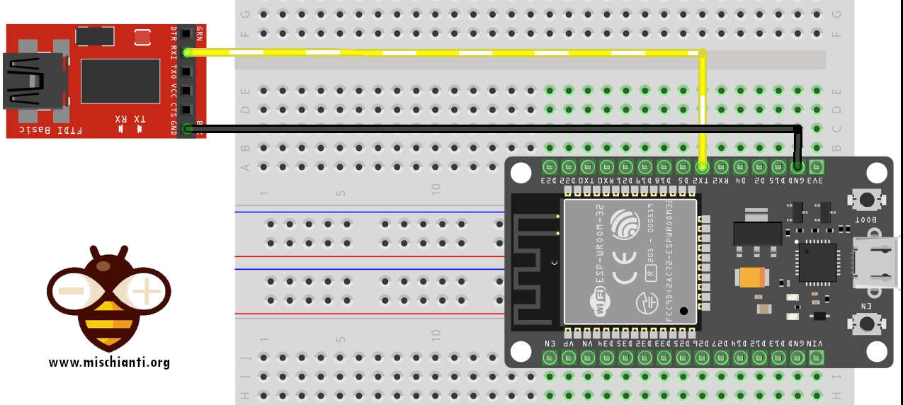
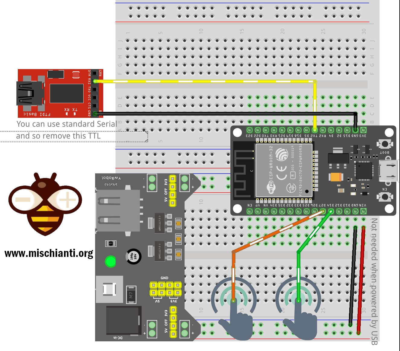
Per il seguente test utilizzo il Serial2 per il debug puoi trovare maggiori informazioni in questo articolo “ESP32: gestire più seriali e logging per il debug“.
Qui lo schema di connessione per utilizzare un FDTI esterno su Serial2.
Il pezzetto di codice wake deve essere residente nella memoria rapida RTC. Questo può essere fatto in due modi.
Il primo modo è utilizzare l’attributo RTC_IRAM_ATTR per inserire una funzione nella memoria RTC:
void RTC_IRAM_ATTR esp_wake_deep_sleep(void) {
    esp_default_wake_deep_sleep();
    // Add additional functionality here
}
Il secondo modo è inserire la funzione in qualsiasi file sorgente il cui nome inizia con rtc_wake_stub. I nomi dei file rtc_wake_stub* hanno il loro contenuto automaticamente inserito nella memoria RTC dal linker.
Conservare i dati durante la sospensione profonda può essere fatto in due modi, ma il più semplice è usare RTC_DATA_ATTR e RTC_RODATA_ATTR per specificare tutti i dati (scrivibili o di sola lettura, rispettivamente) che devono essere caricati nella memoria RTC:
// preserve data
RTC_DATA_ATTR int wake_count;

void RTC_IRAM_ATTR esp_wake_deep_sleep(void) {
    esp_default_wake_deep_sleep();
    // increment data after wake
    wake_count++;
}
Qui uno sketch completo per verificarne il comportamento
/*
 *  ESP32
 *  Variable behaivor in DEEP Sleep
 *  by Mischianti Renzo <https://mischianti.org>
 *
 *  https://mischianti.org/it/esp32-risparmio-energetico-pratico-preservare-i-dati-sveglia-a-tempo-e-tramite-tocco-4/
 *
 */
#include "Arduino.h"

// Preserved value
RTC_DATA_ATTR int wake_count = 0;
RTC_DATA_ATTR int wake_count2 = 0;
// Not preserved
int wake_count3 = 0;

// Call function every wake
void RTC_IRAM_ATTR esp_wake_deep_sleep(void) {
    esp_default_wake_deep_sleep();
    // increment every wake
    wake_count2++;
}

void setup()
{
	  ++wake_count;
	  ++wake_count3;

	Serial2.begin(115200);

	while(!Serial2){delay(500);}

	Serial2.println("Wake count in setup: " + String(wake_count));
	Serial2.println("Wake count2 in setup: " + String(wake_count2));
	Serial2.println("Wake count3 in setup: " + String(wake_count3));

    Serial2.println();
    Serial2.println("DEEP SLEEP ENABLED FOR 5secs");
    delay(100);

    esp_sleep_enable_timer_wakeup(5 * 1000 * 1000);

    esp_deep_sleep_start();

    Serial2.println();
    Serial2.println("DEEP SLEEP WAKE UP");
}

void loop()
{

}
Ecco il risultato della Serial2:
Wake count in setup: 1
Wake count2 in setup: 0
Wake count3 in setup: 1

DEEP SLEEP ENABLED FOR 5secs
Wake count in setup: 2
Wake count2 in setup: 1
Wake count3 in setup: 1

DEEP SLEEP ENABLED FOR 5secs
Wake count in setup: 3
Wake count2 in setup: 2
Wake count3 in setup: 1

DEEP SLEEP ENABLED FOR 5secs
Wake count in setup: 4
Wake count2 in setup: 3
Wake count3 in setup: 1

DEEP SLEEP ENABLED FOR 5secs
Tipi di sveglia
Puoi ottenere alcune informazioni quando lo Sketch si riavvia dal sonno profondo, il primo è la fonte di risveglio e puoi verificarlo con questi comandi
/*
Method to print the reason by which ESP32
has been awaken from sleep
*/
void print_wakeup_reason(){
  esp_sleep_wakeup_cause_t wakeup_reason;

  wakeup_reason = esp_sleep_get_wakeup_cause();

  switch(wakeup_reason)
  {
    case ESP_SLEEP_WAKEUP_EXT0 : Serial2.println("Wakeup caused by external signal using RTC_IO"); break;
    case ESP_SLEEP_WAKEUP_EXT1 : Serial2.println("Wakeup caused by external signal using RTC_CNTL"); break;
    case ESP_SLEEP_WAKEUP_TIMER : Serial2.println("Wakeup caused by timer"); break;
    case ESP_SLEEP_WAKEUP_TOUCHPAD : Serial2.println("Wakeup caused by touchpad"); break;
    case ESP_SLEEP_WAKEUP_ULP : Serial2.println("Wakeup caused by ULP program"); break;
    default : Serial2.printf("Wakeup was not caused by deep sleep: %d\n",wakeup_reason); break;
  }
}
e quando selezioni una particolare fonte di risveglio, you may have commands to retrieve other information, but we’ll see that soon.
Timer
Il controller RTC ha un timer integrato che può essere utilizzato per riattivare il chip dopo un periodo di tempo predefinito. Il tempo è specificato con una precisione al microsecondo, ma la risoluzione effettiva dipende dalla sorgente di clock selezionata per RTC SLOW_CLK.
Questa modalità di attivazione non richiede l’ accensione delle periferiche RTC o delle memorie RTC durante il sonno (controlla l’articolo precedente per capire quali sono i vantaggi) .
esp_err_tesp_sleep_enable_timer_wakeup(uint64_t time_in_us)
Abilita la sveglia tramite timer.
Return
ESP_OKon successESP_ERR_INVALID_ARGif value is out of range
Parameters
time_in_us: time before wakeup, in microseconds (time_in_us * 1000 = milliseconds * 1000 = seconds)
Qui lo sketch completo:
/*
 *  ESP32
 *  DEEP Sleep and timer wake up
 *  by Mischianti Renzo <https://mischianti.org>
 *
 *  https://mischianti.org/it/esp32-risparmio-energetico-pratico-preservare-i-dati-sveglia-a-tempo-e-tramite-tocco-4/
 *
 */

#define TIME_TO_SLEEP  5        	/* Time ESP32 will go to sleep (in seconds) */

RTC_DATA_ATTR int bootCount = 0;

/*
Method to print the reason by which ESP32
has been awaken from sleep
*/
void print_wakeup_reason(){
  esp_sleep_wakeup_cause_t wakeup_reason;

  wakeup_reason = esp_sleep_get_wakeup_cause();

  switch(wakeup_reason)
  {
    case ESP_SLEEP_WAKEUP_EXT0 : Serial2.println("Wakeup caused by external signal using RTC_IO"); break;
    case ESP_SLEEP_WAKEUP_EXT1 : Serial2.println("Wakeup caused by external signal using RTC_CNTL"); break;
    case ESP_SLEEP_WAKEUP_TIMER : Serial2.println("Wakeup caused by timer"); break;
    case ESP_SLEEP_WAKEUP_TOUCHPAD : Serial2.println("Wakeup caused by touchpad"); break;
    case ESP_SLEEP_WAKEUP_ULP : Serial2.println("Wakeup caused by ULP program"); break;
    default : Serial2.printf("Wakeup was not caused by deep sleep: %d\n",wakeup_reason); break;
  }
}

void setup(){
  Serial2.begin(115200);
  delay(1000); //Take some time to open up the Serial Monitor

  //Increment boot number and print it every reboot
  ++bootCount;
  Serial2.println("Boot number: " + String(bootCount));

  //Print the wakeup reason for ESP32
  print_wakeup_reason();

  /*
  First we configure the wake up source
  We set our ESP32 to wake up every 5 seconds
  */
  esp_sleep_enable_timer_wakeup(TIME_TO_SLEEP * 1000 * 1000);
  Serial2.println("Setup ESP32 to sleep for every " + String(TIME_TO_SLEEP) +
  " Seconds");

  Serial2.println("Going to sleep now");
  Serial2.flush();
  esp_deep_sleep_start();
  Serial2.println("This will never be printed");
}

void loop(){
  //This is not going to be called
}
Il risultato è:
Boot number: 1
Wakeup was not caused by deep sleep: 0
Setup ESP32 to sleep for every 5 Seconds
Going to sleep now
Boot number: 2
Wakeup caused by timer
Setup ESP32 to sleep for every 5 Seconds
Going to sleep now
Boot number: 3
Touch
Il modulo RTC IO contiene la logica per attivare la sveglia quando si verifica un interrupt del sensore tattile. È necessario configurare l’interruzione del touch pad prima che il chip inizi la sospensione profonda.
Le revisioni 0 e 1 dell’ESP32 supportano questa modalità di attivazione solo quando le periferiche RTC non sono forzate ad essere accese.
esp_err_t esp_deep_sleep_enable_touchpad_wakeup()
Abilita la sveglia tramite sensore tattile.
Nota : nelle revisioni 0 e 1 dell’ESP32, la sorgente di riattivazione tattile non può essere utilizzata quando il dominio di alimentazione RTC_PERIPH è forzato per essere acceso (ESP_PD_OPTION_ON) o quando viene utilizzata la sorgente di riattivazione ext0.
Return
ESP_OKon successESP_ERR_INVALID_STATEif wakeup triggers conflict
E c’è una funzione per impostare il corretto touch pin di sveglia
void touchAttachInterrupt(uint8_t pin, void (*userFunc)(void), uint16_t threshold);
Seleziona il pin touch corretto e definisce la callback e la soglia.
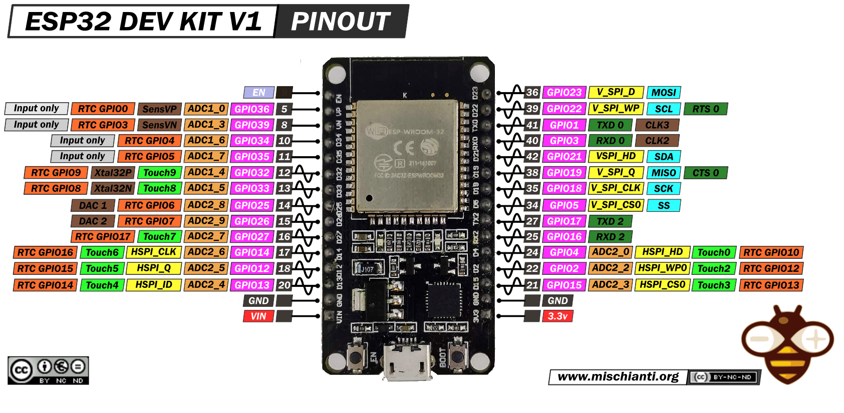
Per ulteriori informazioni sul dispositivo fare riferimento a “DOIT ESP32 DEV KIT v1 immagine di piedinatura ad alta risoluzione e specifiche“.
Qui il codice dei pin touch
T0: GPIO 4T1: GPIO 0T2: GPIO 2T3: GPIO 15T4: GPIO 13T5: GPIO 12T6: GPIO 14T7: GPIO 27T8: GPIO 33T9: GPIO 32
C’è un comando per controllare quali pin sono stati toccati
/*
Method to print the touchpad by which ESP32
has been awaken from sleep
*/
void print_wakeup_touchpad(){
  touchPin = esp_sleep_get_touchpad_wakeup_status();

  switch(touchPin)
  {
    case 0  : Serial2.println("Touch detected on GPIO 4"); break;
    case 1  : Serial2.println("Touch detected on GPIO 0"); break;
    case 2  : Serial2.println("Touch detected on GPIO 2"); break;
    case 3  : Serial2.println("Touch detected on GPIO 15"); break;
    case 4  : Serial2.println("Touch detected on GPIO 13"); break;
    case 5  : Serial2.println("Touch detected on GPIO 12"); break;
    case 6  : Serial2.println("Touch detected on GPIO 14"); break;
    case 7  : Serial2.println("Touch detected on GPIO 27"); break;
    case 8  : Serial2.println("Touch detected on GPIO 33"); break;
    case 9  : Serial2.println("Touch detected on GPIO 32"); break;
    default : Serial2.println("Wakeup not by touchpad"); break;
  }
}
Molto semplice ma molto importante, e lo sketch completo:
/*
 *  ESP32
 *  DEEP Sleep and touch wake up
 *  by Mischianti Renzo <https://mischianti.org>
 *
 *  https://mischianti.org/it/esp32-risparmio-energetico-pratico-preservare-i-dati-sveglia-a-tempo-e-tramite-tocco-4/
 *
 */

#define Threshold 60 /* Greater the value, more the sensitivity */

RTC_DATA_ATTR int bootCount = 0;
touch_pad_t touchPin;
/*
Method to print the reason by which ESP32
has been awaken from sleep
*/
void print_wakeup_reason(){
  esp_sleep_wakeup_cause_t wakeup_reason;

  wakeup_reason = esp_sleep_get_wakeup_cause();

  switch(wakeup_reason)
  {
    case ESP_SLEEP_WAKEUP_EXT0 : Serial2.println("Wakeup caused by external signal using RTC_IO"); break;
    case ESP_SLEEP_WAKEUP_EXT1 : Serial2.println("Wakeup caused by external signal using RTC_CNTL"); break;
    case ESP_SLEEP_WAKEUP_TIMER : Serial2.println("Wakeup caused by timer"); break;
    case ESP_SLEEP_WAKEUP_TOUCHPAD : Serial2.println("Wakeup caused by touchpad"); break;
    case ESP_SLEEP_WAKEUP_ULP : Serial2.println("Wakeup caused by ULP program"); break;
    default : Serial2.printf("Wakeup was not caused by deep sleep: %d\n",wakeup_reason); break;
  }
}

/*
Method to print the touchpad by which ESP32
has been awaken from sleep
*/
void print_wakeup_touchpad(){
  touchPin = esp_sleep_get_touchpad_wakeup_status();

  switch(touchPin)
  {
    case 0  : Serial2.println("Touch detected on GPIO 4"); break;
    case 1  : Serial2.println("Touch detected on GPIO 0"); break;
    case 2  : Serial2.println("Touch detected on GPIO 2"); break;
    case 3  : Serial2.println("Touch detected on GPIO 15"); break;
    case 4  : Serial2.println("Touch detected on GPIO 13"); break;
    case 5  : Serial2.println("Touch detected on GPIO 12"); break;
    case 6  : Serial2.println("Touch detected on GPIO 14"); break;
    case 7  : Serial2.println("Touch detected on GPIO 27"); break;
    case 8  : Serial2.println("Touch detected on GPIO 33"); break;
    case 9  : Serial2.println("Touch detected on GPIO 32"); break;
    default : Serial2.println("Wakeup not by touchpad"); break;
  }
}

void callback(){
  //placeholder callback function
}

void setup(){
  Serial2.begin(115200);
  delay(1000); //Take some time to open up the Serial Monitor

  //Increment boot number and print it every reboot
  ++bootCount;
  Serial2.println("Boot number: " + String(bootCount));

  //Print the wakeup reason for ESP32 and touchpad too
  print_wakeup_reason();
  print_wakeup_touchpad();

  //Setup interrupt on Touch Pad 6 (GPIO14)
  touchAttachInterrupt(T6, callback, Threshold);

  //Setup interrupt on Touch Pad 7 (GPIO27)
  touchAttachInterrupt(T7, callback, Threshold);


  //Configure Touchpad as wakeup source
  esp_sleep_enable_touchpad_wakeup();

  //Go to sleep now
  Serial2.println("Going to sleep now");
  esp_deep_sleep_start();
  Serial2.println("This will never be printed");
}

void loop(){
  //This will never be reached
}
e qui un pezzo dell’output della Serial2:
Boot number: 3
Wakeup caused by touchpad
Touch detected on GPIO 14
Going to sleep now
Boot number: 4
Wakeup caused by touchpad
Touch detected on GPIO 27
Going to sleep now
Boot number: 5
Grazie
- ESP32: piedinatura, specifiche e configurazione dell’Arduino IDE
- ESP32: fileSystem integrato SPIFFS
- ESP32: gestire più seriali e logging per il debug
- ESP32 risparmio energetico pratico
- ESP32 risparmio energetico pratico: gestire WiFi e CPU
- ESP32 risparmio energetico pratico: modem e light sleep
- ESP32 risparmio energetico pratico: deep sleep e ibernazione
- ESP32 risparmio energetico pratico: preservare dati al riavvio, sveglia a tempo e tramite tocco
- ESP32 risparmio energetico pratico: sveglia esterna e da ULP
- ESP32 risparmio energetico pratico: sveglia da UART e GPIO
- ESP32: filesystem integrato LittleFS
- ESP32: filesystem integrato FFat (Fat/exFAT)
- ESP32-wroom-32
- ESP32-CAM
- ESP32: ethernet w5500 con chiamate standard (HTTP) e SSL (HTTPS)
- ESP32: ethernet enc28j60 con chiamate standard (HTTP) e SSL (HTTPS)
- Come usare la scheda SD con l’esp32
- esp32 e esp8266: file system FAT su memoria SPI flash esterna
- Gestione aggiornamenti firmware e OTA
- Gestione del firmware
- Aggiornamento OTA con Arduino IDE
- Aggiornamento OTA con browser web
- Aggiornamenti automatici OTA da un server HTTP
- Aggiornamento del firmware non standard
- Integrare LAN8720 con ESP32 per la connettività Ethernet con plain (HTTP) e SSL (HTTPS)
- Collegare l’EByte E70 (CC1310) ai dispositivi ESP32 c3/s3 ed un semplice sketch di esempio
- ESP32-C3: piedinatura, specifiche e configurazione dell’IDE Arduino
- Integrazione del modulo W5500 su ESP32 con Core 3: supporto nativo ai protocolli Ethernet con SSL e altre funzionalità
- Integrazione del modulo LAN8720 su ESP32 con Core 3: supporto nativo del protocollo Ethernet con SSL e altre funzionalità.
- Dallas DS18B20
- Guida all’I2C su ESP32: comunicazione con dispositivi eterogenei 5v 3.3v, gestione interfacce aggiuntive
- Display
- Guida Completa: Come Usare un Display ILI9341 con la Libreria TFT_eSPI
- Come integrare la funzionalità touch screen nel display TFT ILI9341
- Display eInk SSD1683 con GxEPD e ESP32 (e HMI CrowPanel 4,2″): nozioni di base e configurazione