i2c, SPI and UART compared
I2C, SPI, and UART are protocols that we encounter all the time in this world, but why do we need all these protocols to interconnect external peripherals? Well! The answer is simple because there are many needs to be met, and each protocol has a well-defined scope.
In this article, we will make a summary comparison always to be able to select the correct protocol.
UART
A universal asynchronous receiver transmitter (UART) is a computer hardware device for asynchronous serial communication in which the data format and transmission speeds are configurable. It sends data bits one by one, from the least significant to the most significant, framed by start and stops bits so that the communication channel handles precise timing. A driver circuit external to the UART handles the electric signaling levels.
Speed
The data rate of a UART interface is similar to that of an I2C interface. UART interfaces have a maximum data rate of around 5 Mbps. There is also some protocol overhead in the form of start, stop, and parity bits.
Interface
- TxD: Transmit Data
- RxD: Receive Data
The polarity of the signals is +5 V for mark or high and 0 V for space or low. However, serial data transmission along the wire in an RS232 transmission interface requires −15 to −12 V for mark and +12 to +15 V for space. Line drivers are used to convert the logic levels required by the UART to those needed for the RS232 interface pins TD and RD.
TTL – Transistor-Transistor Logic is not a protocol. It’s an older technology for digital logic, but the name is often used to refer to the 5 V supply voltage, usually incorrectly referring to what should be called UART.
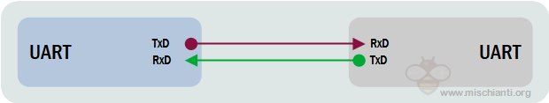
It can operate between devices in 3 ways:
- Simplex = data transmission in one direction
- Half-duplex = data transmission in either direction but not simultaneously
- Full-duplex = data transmission in both directions simultaneously
Distance
A UART can work over long distances with appropriate line drivers: from 15 meters (m) for the RS-232 serial data bus to 1000m for RS-485 or RS-422 interfaces. The distance is also influenced by cable quality and baud rate.
Communication
- Transmitting UART converts parallel data from the primary device (e.g. CPU) into serial form and transmits it to receiving UART. It will then convert the serial data back into parallel data for the receiving device.
- As UART has no clocks, UART adds start and stop bits that are being transferred.
- This helps the receiving UART know when to start reading bits as the bits represent the start and the end of the data packet. When the receiving UART detects a start bit, it will read the bits at the BAUD rate.
- UART data transmission speed is called BAUD Rate and is set to 115,200 by default (BAUD rate is based on symbol transmission rate but is similar to bit rate).
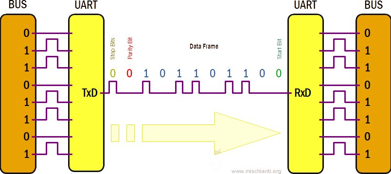
Packet

- Start Bit: UART data transmission line is usually held at a high voltage level when it’s not transmitting data. The transmitting UART pulls the transmission line from high to low for one clock cycle to start the transfer of data.
- Data Frame: contains the actual data being transferred. If a parity bit is used, it can be 5 bits up to 8 bits long. The data frame can be 9 bits long if no parity bit is used. In most cases, the data is first sent with the least significant bit.
- Parity: describes the evenness or oddness of a number. The parity bit allows the receiving UART to tell if any data has changed during transmission. It counts the number of bits with a value of 1 and checks if the total is an even or odd number.
- Stop Bits: to signal the end of the data packet, the sending UART drives the data transmission line from a low voltage to a high voltage for 1 to two 2 bits duration.
Summary
Advantages
- It’s straightforward to operate, has a lot of standard protocol (RS-232, RS-485, or RS-422), and can be managed entirely by the hardware;
- It’s widely supported (all devices with nine pin connector can use It);
- No clock is needed;
- Long-distance;
- Parity bit to allow for error checking.
Disadvantages
- Communication with only two devices;
- The size of the data frame is limited to only 9 bits;
- Only fixed data rate (specified at the beginning).
I2C
I2C (Inter-Integrated Circuit, eye-squared-C) is alternatively known as I2C or IIC. It is a synchronous, multi-master, multi-slave, packet-switched, single-ended, serial communication bus. Invented in 1982 by Philips Semiconductors. It is widely used for attaching lower-speed peripheral ICs to processors and microcontrollers in short-distance, intra-board communication. (cit. WiKi)
Speed
I2C supports 100 kbps, 400 kbps, and 3.4 Mbps. Some variants also support 10 Kbps and 1 Mbps.
| Mode | Maximum speed | Maximum capacitance | Drive | Direction |
|---|---|---|---|---|
| Standard-mode (Sm) | 100 kbit/s | 400 pF | Open drain | Bidirectional |
| Fast-mode (Fm) | 400 kbit/s | 400 pF | Open drain | Bidirectional |
| Fast-mode Plus (Fm+) | 1 Mbit/s | 550 pF | Open drain | Bidirectional |
| High-speed mode (Hs) | 1.7 Mbit/s | 400 pF | Open drain | Bidirectional |
| High-speed mode (Hs) | 3.4 Mbit/s | 100 pF | Open drain | Bidirectional |
| Ultra Fast-mode (UFm) | 5 Mbit/s | Push-pull | Unidirectional |
Interface
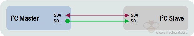
Like UART communication, I2C only uses two wires to transmit data between devices:
- SDA (Serial Data) – The line for the master and slave to send and receive data.
- SCL (Serial Clock) – The line that carries the clock signal (common clock signal between multiple masters and multiple slaves).
I2C is a serial communication protocol, so data is transferred bit by bit along a single wire (the SDA line).
Like SPI, I2C is synchronous, so the output of bits is synchronized to the sampling of bits by a clock signal shared between the master and the slave. The master always controls the clock signal.
There will be multiple slaves and multiple masters, and all masters can communicate with all the slaves.

- Start: The SDA line switches from a high voltage level to a low voltage level before the SCL line switches from high to low.
- Stop: The SDA line switches from a low voltage level to a high voltage level after the SCL line switches from low to high.
- Address Frame: A 7 or 10-bit sequence unique to each slave identifies the slave when the master wants to talk to it.
- Read/Write Bit: A single bit specifying whether the master is sending data to the slave (low voltage level) or requesting data from it (high voltage level).
- ACK/NACK Bit: Each frame in a message is followed by an acknowledge/no-acknowledge bit. If an address frame or data frame was successfully received, an ACK bit is returned to the sender from the receiving device.
Devices connections
Because I2C uses addressing, multiple slaves can be controlled by a single master. Up to 27 slave devices can be connected/addressed in the I2C interface circuit. With a 7-bit address, 128 (27) unique addresses are available. Using 10-bit addresses is uncommon but provides 1,024 (210) unique addresses.
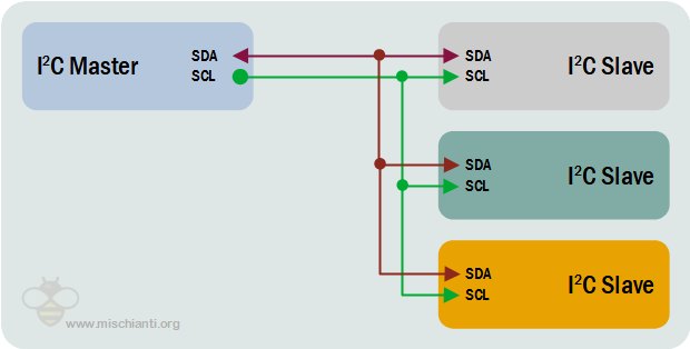
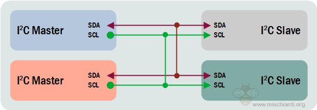
Multiple masters can be connected to a single slave or multiple slaves. The problem with multiple masters in the same system comes when two masters try to send or receive data simultaneously over the SDA line. Each master needs to detect if the SDA line is low or high before transmitting a message to solve this problem. If the SDA line is low, this means that another master has control of the bus, and the master should wait to send the message. If the SDA line is high, then it’s safe to transmit the message. To connect multiple masters to multiple slaves
Distance
The vast majority of applications use I2C in the way it was designed initially—peripheral ICs directly wired to a processor on the same printed circuit board, and therefore over relatively short distances of less than 1 foot (30 cm) without a connector. However, using a different driver, an alternate version of I2C can communicate up to 20 meters (possibly over 100 meters) over CAT5 or other cables.
Summary
Advantages
- Support multiple masters and slaves;
- Few wires for multiple devices.
Disadvantages
- I2C interface is a half-duplex;
- Slower speed as it requires pull-up resistors rather than push-pull resistors used by SPI. It also has an open-drain design = limited speed;
- More logic on software stack for addressing.
SPI
The Serial Peripheral Interface (SPI) is a synchronous serial communication interface specification used for short-distance communication, primarily in embedded systems. SPI devices communicate in full-duplex mode using a master-slave architecture with a single master. The master device originates the frame for reading and writing. Multiple slave-devices are supported through selection with individual slave select (SS), sometimes called chip select (CS), lines.
Speed
The maximum data rate limit is not specified in the SPI interface. Usually supports about 10 Mbps to 20 Mbps.
There is no standard set of speeds defined for the SPI protocol. Typical bus speeds are in the 50 MHz range. Since there is no overhead added by the protocol, such as addressing and flow control, the throughput that can be achieved using SPI mirrors the clock frequency. For a 50 MHz SPI line, the throughput is 50 Mbps. One more thing to remember is that the communication is full-duplex. So, the effective throughput in the case mentioned can be as high as 100 Mbps (if both the master and slave can send meaningful data to each other).
Interface
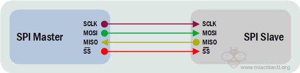
The SPI bus specifies four logic signals:
- SCLK: Serial Clock (output from master)
- MOSI: Master Out Slave In (data output from master)
- MISO: Master In Slave Out (data output from slave)
- SS: Slave Select (often active low, output from master)
Slave Select has the same functionality as chip select and is used instead of an addressing concept. MOSI on a master connects to MOSI on a slave. MISO on a master connects to MISO on a slave.
Note: on a slave-only device, MOSI may be labeled as SDI (Serial Data In), and MISO may be labeled as SDO (Serial Data Out)
The signal names above can be used to label both the master and slave device pins as well as the signal lines between them in an unambiguous way and are the most common in modern products. Pin names are always capitalized e.g. “Slave Select,” not “slave select.”
Older products can have nonstandard SPI pin names:
- Serial Clock:
- SCK
- Master Output → Slave Input (MOSI):
- SIMO, MTSR – correspond to MOSI on both master and slave devices, connect to each other
- SDI, DI, DIN, SI – on slave devices; connects to MOSI on master, or to below connections
- SDO, DO, DOUT, SO – on master devices; connects to MOSI on slave, or above connections
- Master Input ← Slave Output (MISO):
- SOMI, MRST – correspond to MISO on both master and slave devices, connect to each other
- SDO, DO, DOUT, SO – on slave devices; connects to MISO on master, or to below connections
- SDI, DI, DIN, SI – on master devices; connect to MISO on slave or above connections
- Slave Select:
- SS, SS, SSEL, nSS, /SS, SS# (slave select)
- CS, CS (chip select)
- CSN (chip select/enable)
- CE (chip enable)
Each company or manufacturer has its own specific protocols to communicate with peripherals. Hence one needs to read the datasheet to know the read/write protocol for SPI communication to be established. For example, we would like SPI communication between the microcontroller and EPROM. Here one needs to go through the read/write operational diagram in the EPROM datasheet.
Communication
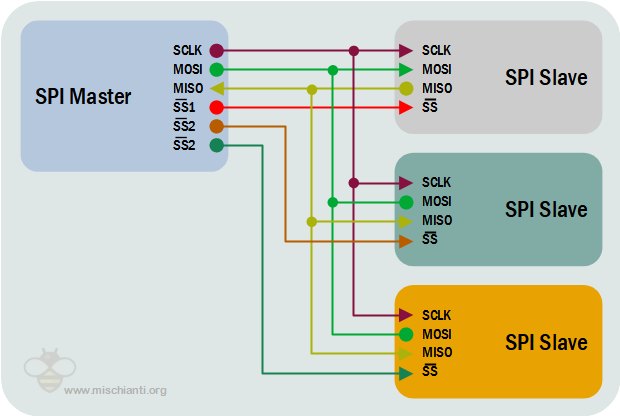
Each slave requires a separate enable signal in a multi-slave system, which is slightly more complicated on hardware than the I2C system.
The SPI interface is actually two simple shift registers in the internal hardware. It is transmitted bit by bit under the slave enable signal and shift pulse generated by the master device. The transmitted data is 8 bits. The high bit is in the front, and the low bit is in the back.
The SPI interface is synchronous serial data transmission between the CPU and the low-speed peripheral device. Under the shift pulse of the master device, the data is transmitted bit by bit. The high bit is in the front, and the low bit is in the back. It is full-duplex communication, and the data transmission speed is overall faster than the I2C bus that can reach speeds of a few Mbps.
Distance
While the SPI communication method is generally suitable for distances up to approximately 10m can bridge longer distances, a repeater is often needed because of attenuation due to the increased line resistance of long cables.
Summary
Advantages
- It’s simple to manage without a complex software stack for addressing;
- No, start and stop bits, unlike UART, which means data can be transmitted continuously without interruption
- Full-duplex communication, fastest;
- SPI uses push-pull, and hence higher data rates and longer ranges are possible;
- SPI uses less power compared to I2C.
Disadvantages
- As the number of slaves increases, the number of CS lines increases, this results in hardware complexity as the number of pins required will increase;
- A lot of slaves mean a lot of wires;
- There is no flow control specified, and no acknowledgment mechanism confirms whether data is received, unlike I2C;
- No form of an error check, unlike in UART (using parity bit);
- Short distance.
Comparison table
| UART | I2C | SPI | |
|---|---|---|---|
| Full name | Universal Asynchronous Receiver-Transmitter | Inter-Integrated Circuit | Serial Peripheral Interface |
| Complexity | Very low | Low with a lot of devices also | Complex wiring and management with a lot of devices |
| Min wires | 2 | 2 | 4 |
| Duplex | Full-duplex | Half-duplex | Full-Duplex |
| Type of communication | Asynchronous | Synchronous | Synchronous |
| Slave number | 1 | 128 with default 7-bit address. By default, up to 27 slave devices can be connected/addressed in the I2C interface circuit. | Limited by the available SS pins |
| Master number | Not Application | One or more | 1 |
| Distance | from 15 to 1000m | from 20 to 100m | more than 10m |
| Speed | max data rate around 5Mbps | max data rate around 3.4Mbps to 5Mbps | default max data rate around 50Mbps but with particular condition 100Mbps |
Conclusion
For me, there isn’t a winner, and all protocols have Their scope. UART can be used for long distances and when you want a simple protocol implementation. i2c can be used to connect many low-speed devices with simple hardware connections. SPI can be used with some high-speed devices.