
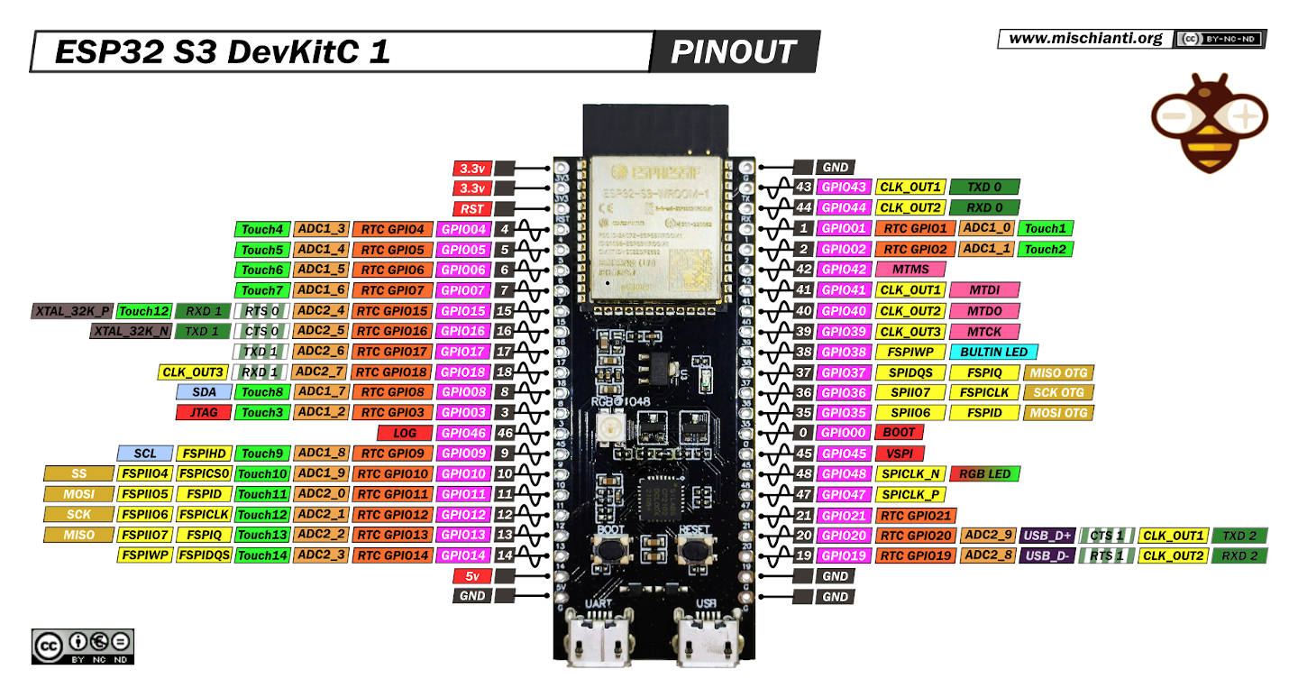
ESP32 S3 DevKitC 1: high-resolution pinout and specs
The evolution of microcontroller technology has changed the face of hardware development, enabling creators to realize complex applications more efficiently and cost-effectively.
The ESP32-S3 DevKitC-1, developed by Espressif Systems, is an exciting entrant in this realm.
ESP32-S3 DevKitC-1 is a small-sized yet powerful development board equipped with the robust ESP32-S3 System-on-Chip (SoC). It features a full Wi-Fi & Bluetooth/BLE 5.0 stack, making it an excellent choice for IoT applications.
This article explores the key features of the ESP32-S3 DevKitC-1 and provides a comprehensive pinout guide for developers.
Here where to buy a short selection of esp32s3 ESP32 S3 Purlple AI-S3 - YD-ESP32-S3 - ESP32-S3-DevKitC-1 - ESP32-S3-DevKitC-1 - ESP32-S3 Board screen - ESP32-S3 Zero
Specifications
| Key Component | Description |
|---|---|
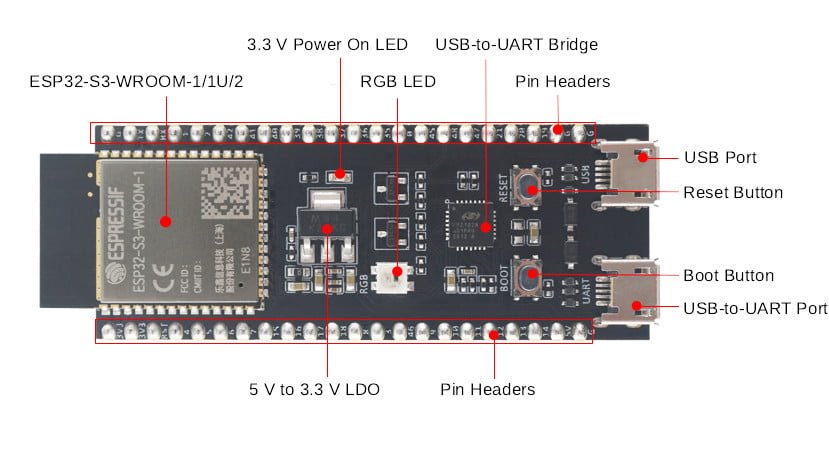
| ESP32-S3-WROOM-1/1U/2 | ESP32-S3-WROOM-1, ESP32-S3-WROOM-1U, and ESP32-S3-WROOM-2 are powerful, generic Wi-Fi + Bluetooth LE MCU modules that have a rich set of peripherals. They provide acceleration for neural network computing and signal processing workloads. ESP32-S3-WROOM-1 and ESP32-S3-WROOM-2 comes with a PCB antenna. ESP32-S3-WROOM-1U comes with an external antenna connector. |
| 5 V to 3.3 V LDO | Power regulator that converts a 5 V supply into a 3.3 V output. |
| Pin Headers | All available GPIO pins (except for the SPI bus for flash) are broken out to the pin headers on the board for easy interfacing and programming. For details, please see Header Block. |
| USB-to-UART Port | A Micro-USB port used for power supply to the board, for flashing applications to the chip, as well as for communication with the chip via the on-board USB-to-UART bridge. |
| Boot Button | Download button. Holding down Boot and then pressing Reset initiates Firmware Download mode for downloading firmware through the serial port. |
| Reset Button | Press this button to restart the system. |
| USB Port | ESP32-S3 full-speed USB OTG interface, compliant with the USB 1.1 specification. The interface is used for power supply to the board, for flashing applications to the chip, for communication with the chip using USB 1.1 protocols, as well as for JTAG debugging. |
| USB-to-UART Bridge | Single USB-to-UART bridge chip provides transfer rates up to 3 Mbps. |
| RGB LED | Addressable RGB LED, driven by GPIO48, and you can use LED_BUILTIN (49+48=97) as normal LED. |
| 3.3 V Power On LED | Turns on when the USB power is connected to the board. |
In boards featuring ESP32-S3-WROOM-1/1U modules with Octal SPI flash/PSRAM memory, or ESP32-S3-WROOM-2 modules, the GPIO35, GPIO36, and GPIO37 pins are reserved for internal communication between the ESP32-S3 and the SPI flash/PSRAM memory.
CPU and Memory
- Xtensa® dual-core 32-bit LX7 microprocessor,
up to 240 MHz - CoreMark® score:
– 1 core at 240 MHz: 613.86 CoreMark; 2.56 CoreMark/MHz
– 2 cores at 240 MHz: 1181.60 CoreMark; 4.92 CoreMark/MHz - 128-bit data bus and SIMD commands
- 384 KB ROM
- 512 KB SRAM
- 16 KB SRAM in RTC
- SPI, Dual SPI, Quad SPI, Octal SPI, QPI and OPI interfaces that allow connection to multiple flash and external RAM
- Flash controller with cache is supported
- Flash in-Circuit Programming (ICP) is supported
Advanced Peripheral Interfaces
- 45 × programmable GPIOs
- Digital interfaces:
– 4 × SPI
– 1 × LCD interface (8-bit ~16-bit parallel RGB, I8080 and MOTO6800), supporting conversion between RGB565, YUV422, YUV420 and YUV411
– 1 × DVP 8-bit ~16-bit camera interface
– 3 × UART
– 2 × I2C
– 2 × I2S
– 1 × RMT (TX/RX)
– 1 × pulse counter
– LED PWM controller, up to 8 channels
– 1 × full-speed USB OTG
– 1 × USB Serial/JTAG controller
– 2 × MCPWM
– 1 × SDIO host controller with 2 slots
– General DMA controller (GDMA), with 5 transmit channels and 5 receive channels Espressif Systems 3
Submit Documentation Feedback ESP32-S3 Series Datasheet v1.6
– 1 × TWAI® controller, compatible with ISO 11898-1 (CAN Specification 2.0) - Analog interfaces:
– 2 × 12-bit SAR ADCs, up to 20 channels
– 1 × temperature sensor
– 14 × touch sensing IOs Timers:
– 4 × 54-bit general-purpose timers
– 1 × 52-bit system timer
– 3 × watchdog timers
Every variant has its Flash management.
| Ordering Code | Module Integrated | Flash | PSRAM | SPI Voltage |
|---|---|---|---|---|
| ESP32-S3-DevKitC-1-N8 | ESP32-S3-WROOM-1-N8 | 8 MB QD | — | 3.3 V |
| ESP32-S3-DevKitC-1-N8R2 | ESP32-S3-WROOM-1-N8R2 | 8 MB QD | 2 MB QD | 3.3 V |
| ESP32-S3-DevKitC-1-N8R8 | ESP32-S3-WROOM-1-N8R8 | 8 MB QD | 8 MB OT | 3.3 V |
| ESP32-S3-DevKitC-1-N16R8V | ESP32-S3-WROOM-2-N16R8V | 16 MB OT | 8 MB OT | 1.8 V |
| ESP32-S3-DevKitC-1-N32R8V | ESP32-S3-WROOM-2-N32R8V | 32 MB OT | 8 MB OT | 1.8 V |
| ESP32-S3-DevKitC-1U-N8 | ESP32-S3-WROOM-1U-N8 | 8 MB QD | — | 3.3 V |
| ESP32-S3-DevKitC-1U-N8R2 | ESP32-S3-WROOM-1U-N8R2 | 8 MB QD | 2 MB QD | 3.3 V |
| ESP32-S3-DevKitC-1U-N8R8 | ESP32-S3-WROOM-1U-N8R8 | 8 MB QD | 8 MB OT | 3.3 V |
Wi-Fi
- IEEE 802.11 b/g/n-compliant
- Supports 20 MHz, 40 MHz bandwidth in 2.4 GHz band
- 1T1R mode with data rate up to 150 Mbps
- Wi-Fi Multimedia (WMM)
- TX/RX A-MPDU, TX/RX A-MSDU
- Immediate Block ACK
- Fragmentation and defragmentation
- Automatic Beacon monitoring (hardware TSF)
- 4 × virtual Wi-Fi interfaces
- Simultaneous support for Infrastructure BSS in Station, SoftAP, or Station + SoftAP modes Note that when ESP32-S3 scans in Station mode, the SoftAP channel will change along with the Station channel
- Antenna diversity
- 802.11mc FTM
Bluetooth
- Bluetooth LE: Bluetooth 5, Bluetooth mesh
- High power mode (20 dBm)
- Speed: 125 Kbps, 500 Kbps, 1 Mbps, 2 Mbps
- Advertising extensions
- Multiple advertisement sets
- Channel selection algorithm #2
- Internal co-existence mechanism between Wi-Fi and Bluetooth to share the same antenna
Low Power Management
- Power Management Unit with five power modes
- Ultra-Low-Power (ULP) coprocessors:
– ULP-RISC-V coprocessor
– ULP-FSM coprocessor
Security
- Secure boot
- Flash encryption
- 4-Kbit OTP, up to 1792 bits for users
- Cryptographic hardware acceleration:
– AES-128/256 (FIPS PUB 197)
– Hash (FIPS PUB 180-4)
– RSA
– Random Number Generator (RNG)
– HMAC
– Digital signature
How to
- ESP32: pinout, specs and Arduino IDE configuration
- ESP32: integrated SPIFFS Filesystem
- ESP32: manage multiple Serial and logging
- ESP32 practical power saving
- ESP32 practical power saving: manage WiFi and CPU
- ESP32 practical power saving: modem and light sleep
- ESP32 practical power saving: deep sleep and hibernation
- ESP32 practical power saving: preserve data, timer and touch wake up
- ESP32 practical power saving: external and ULP wake up
- ESP32 practical power saving: UART and GPIO wake up
- ESP32: integrated LittleFS FileSystem
- ESP32: integrated FFat (Fat/exFAT) FileSystem
- ESP32-wroom-32
- ESP32-CAM
- ESP32: use ethernet w5500 with plain (HTTP) and SSL (HTTPS)
- ESP32: use ethernet enc28j60 with plain (HTTP) and SSL (HTTPS)
- How to use SD card with esp32
- esp32 and esp8266: FAT filesystem on external SPI flash memory
- Firmware and OTA update management
- Firmware management
- OTA update with Arduino IDE
- OTA update with Web Browser
- Self OTA uptate from HTTP server
- Non-standard Firmware update
- Integrating LAN8720 with ESP32 for Ethernet Connectivity with plain (HTTP) and SSL (HTTPS)
- Connecting the EByte E70 to ESP32 c3/s3 devices and a simple sketch example
- ESP32-C3: pinout, specs and Arduino IDE configuration
- Integrating W5500 with ESP32 Using Core 3: Native Ethernet Protocol Support with SSL and Other Features
- Integrating LAN8720 with ESP32 Using Core 3: Native Ethernet Protocol Support with SSL and Other Features
- Dallas ds18b20:
- Guide to I2C on ESP32: Communication with Heterogeneous 5V and 3.3V Devices, Additional Interface Management and Scanner
- Display
- Complete Guide: Using an ILI9341 Display with the TFT_eSPI Library
- Integrating Touch Screen Functionality with Your ILI9341 TFT Display
- SSD1683 eInk Display with GxEPD and ESP32 (and CrowPanel 4.2″ HMI): basics and configuration
Datasheet
ESP32s3 datasheet
Board Schematic
PCB size
Thanks
- Arduino
- esp8285
- esp8266
- ESP32
- DOIT ESP32 DEV KIT v1
- ESP32 DevKitC v4
- ESP32 WeMos LOLIN32
- ESP32 WeMos LOLIN32 Lite
- ESP32 WeMos LOLIN D32
- ESP32-wroom-32
- NodeMCU-32S
- ESP32-S
- ESP32-CAM
- ESP32-2432S028 (Cheap Yellow Display)
- ESP32-2432S032 (Cheap Yellow Display)
- ESP32 s2
- ESP32c3
- ESP32s3
- Arduino SAMD
- STM32
- Raspberry Pi


Hi Renzo
How and where have you created this beautiful pinout chart?
I have thos board from aliexpress https://s.click.aliexpress.com/e/_DEHFK9x
I can’t find enough details so far and willing to create at least a pinout for myself and others)
Thanks in advance!
Hi Oleksandr,
I did It with a standard graphical editor, for the specs I search on datasheet.
I already have one of that, and I’m going to publish the pinout soon.
Bye Renzo
AFAIK are the default SPI pins on an ESP32-S3:
SS = 10; MOSI = 11; SCK = 12; and MISO = 13.
//Find the default SPI pins for your board
//Make sure you have the right board selected in Tools > Boards
Serial.println(“\nDefault SPI pins for this board:”) ;
Serial.print(” SS: “);
Serial.println(SS);
Serial.print(“MOSI: “);
Serial.println(MOSI);
Serial.print(” SCK: “);
Serial.println(SCK);
Serial.print(“MISO: “);
Serial.println(MISO);
Hi Marius,
I select the standard ESP32S3 Dev Module and I have this pin_variant
I use the core 2.0.11.
Can you check with your setting.
Thanks Renzo
Hi ,
I found a mistake on your ESP32 S”3 pin out picture on the top of this page. I think that you have invert SPI MISO and SPI CLK pin . GPIO12 is CLK and GPIO13 is MISO in the Espressif standard pinout document.
Best regards
Hi Joel,
azz… yes you are right…
I’m going to fix.
Thanks again Renzo
Hi!
You may want to add at the top that you have added the Arduino pinmap (ESP32 S3 Dev Module), sometimes you do!
Also, if you use the ESP32 S3 Dev Module setting, I assume that regardless what board you have (Waveshare Mini S3, etc.) you simply look-up the GPIO on the diagram and cross-reference it to your (excellent) pinout to get the Arduino function for that pin?
Hi Bubba,
yes I add the Arduino Pinout (for the serial) but there is also the “original” pinout with banded color.
For every board normally i retrieve the datasheet and then, I must, every time read the esp32 core for the correct function of the pin, because It change every time.
Bye Renzo