EByte RF E70 Module Adapter: PCB, 3D Printed, Breadboard-Friendly Solution and configuration
To enhance the ease of use for complex modules in electronics, I’m going to show my 3D-printed adapter for the EByte RF E70 module. This design, following the footsteps of my previous projects for the ESP12 and ESP32, focuses on making the E70 module breadboard-friendly for straightforward initial configuration using a PC USB.
Crafting the E70 Module Adapter
The E70 module adapter is a testament to the versatility and utility of 3D printing in electronics. The adapter is specifically tailored to fit the E70 module, featuring precise holes for wire insertion. This ensures a seamless connection to the breadboard, mirroring the user-friendly approach of my previous adapters.
The choice of material for the 3D printed adapter balances durability with ease of use, a hallmark of my design philosophy. The adapter not only fits perfectly with the E70 module but also maintains the integrity of the breadboard setup.
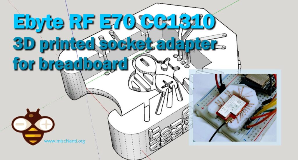
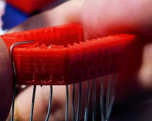
3D printed socket for breadboard
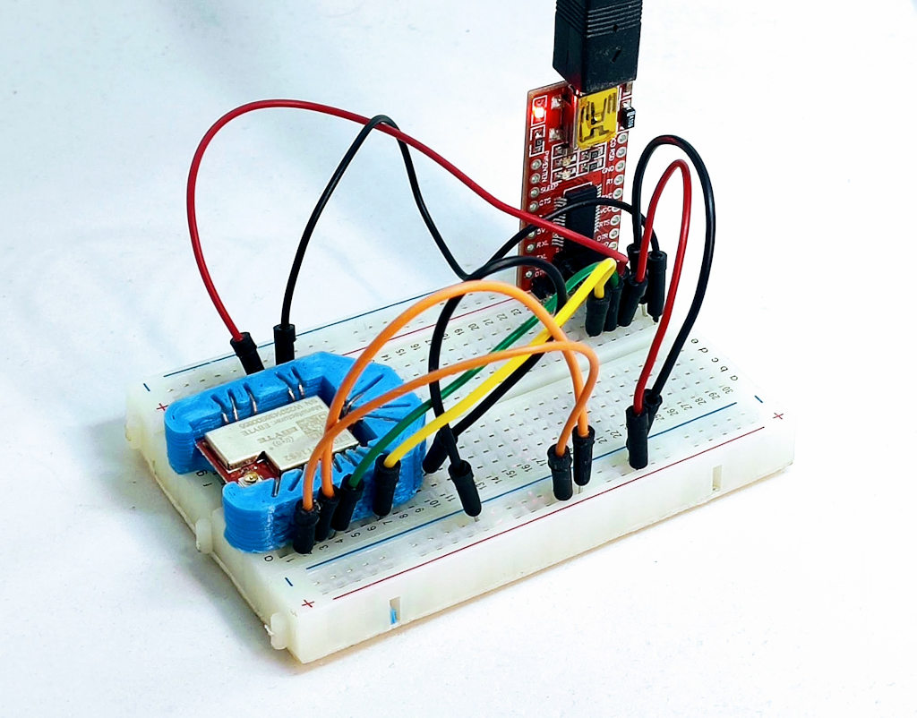
I created a simple socket with my 3D printer to quickly prototype (and manage) the E70 S2; here is the 3D model and the result on a breadboard.
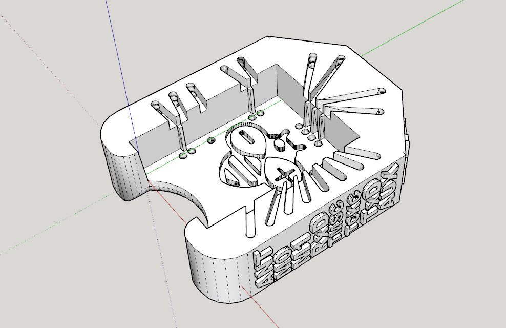
It’s very simple and uses the same technique as other sockets I already created.
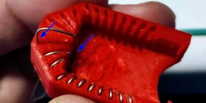
After printing, you must add writing inside the hole.
Insert it into the innermost holes and push it out about 3mm
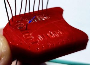
Bend the wire to the external of the adapter.
Cut the external part of the wire, and extract
then reinsert in the internal and external holes.
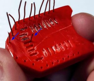
Now check if you need to cut more of the wire of the internal hole and bend It.
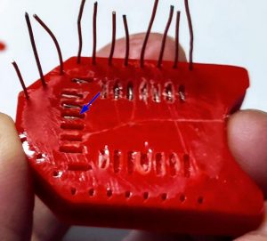
Repeat for all pins. The result It’s very satisfying.
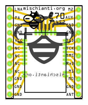
PCB adapter
A more stable solution is to use is to create a PCB, here the board adapter.
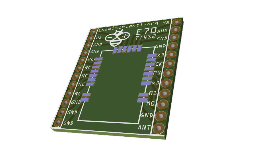
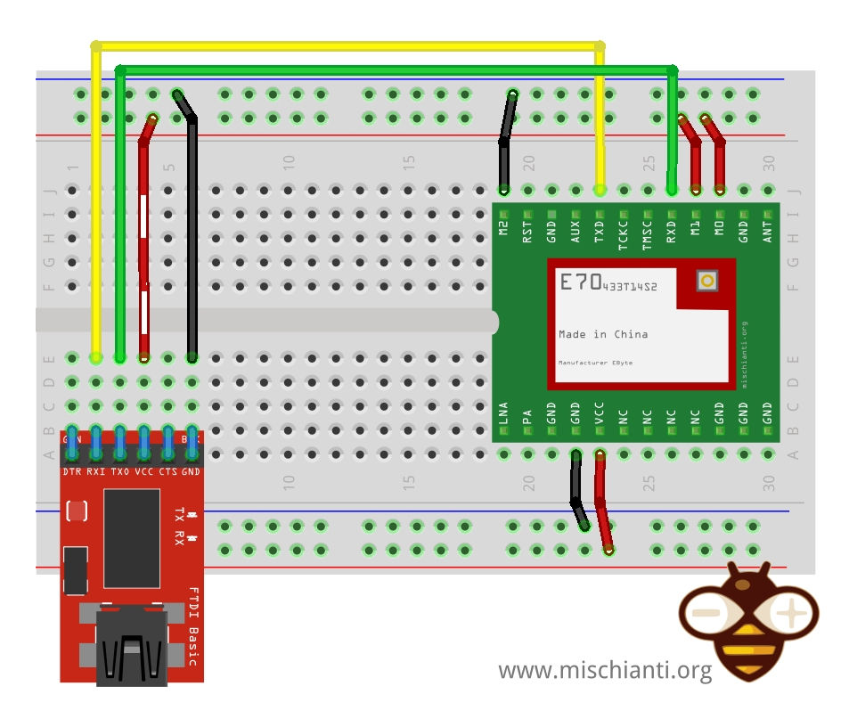
Here is the schema.
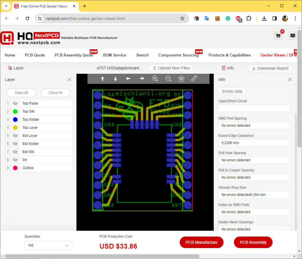
For the PCB, I advise you to use the online service from NextPCB; you can do the preview and the order via this page.
Use a UART device with the EByte program.
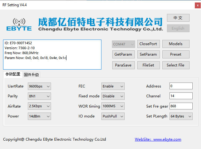
The RF Setting program provided by EByte is a specialized software tool designed to configure RF devices, such as the EByte RF E70 module. This program allows users to customize various parameters and settings related to the radio frequency (RF) communication of the device. Here’s a technical description of its key features and functionalities:
- Frequency Configuration: One of the primary functions is to set the operating frequency of the RF device. This includes selecting the specific frequency bands that are compliant with regional regulations (e.g., 868 MHz for Europe, 915 MHz for North America).
- Transmission Power Control: Users can adjust the transmission power level of the RF device. This is crucial for managing the range and energy consumption of the device.
- Modulation and Bandwidth Settings: The software allows for the adjustment of modulation parameters, including bandwidth, spreading factor, and coding rate. These settings are essential for balancing data rate, range, and resistance to interference.
- Network Settings: You can specify the Address and Channel.
- Firmware Update and Management: The software may also facilitate firmware updates for the RF module, ensuring the device operates with the latest features and security patches.
- Diagnostics and Testing: Tools for diagnosing and testing the RF performance of the device, including signal strength indicators and transmission tests, are typically included.
- Saving and Loading Configurations: Users can save their configurations and load them later, making it easier to manage multiple devices or restore settings.
The RF Setting program is an essential tool for developers and engineers working with RF technology, providing a comprehensive and accessible means to tailor the performance of their devices to specific application needs.
You can use the EByte program that I share also in the GitHub repository here.
The program is designed to connect with the RF device via a USB-to-serial interface or directly through a microcontroller’s serial port. For modules like the E70, a breadboard and jumper wires are often used for physical connections.
Once the E70 module is mounted on the breadboard with the help of the 3D printed adapter, it can be easily connected to a PC via a USB interface. This connection is facilitated by an FTDI adapter, bridging the module and the computer for configuration.
The configuration process is streamlined with the use of EByte’s RFSettings software. This intuitive software allows users to adjust and set various parameters of the E70 module effortlessly, making it ideal for both beginners and seasoned professionals.
This 3D-printed adapter for the EByte RF E70 module represents a step forward in my ongoing efforts to simplify the use of advanced electronic modules. It not only improves the accessibility of the E70 module for both hobbyists and professionals, but also demonstrates the practical applications of 3D printing in custom electronic setups. The creation of this adapter, together with its predecessors for ESP modules, is supported by the desire to adopt easy-to-use and cost-saving solutions in the world of electronics.
Thanks
- EByte RF E70 433/868/900 T14S2: pinout, datasheet and specs (1.5Km)
- EByte RF E70 Module Adapter: PCB, 3D Printed, Breadboard-Friendly Solution and configuration
- Connecting the EByte E70 to ESP32 c3/s3 devices and a simple sketch example
- Connecting the EByte E70 to Arduino SAMD (Nano 33, MKR…) devices and a simple sketch example