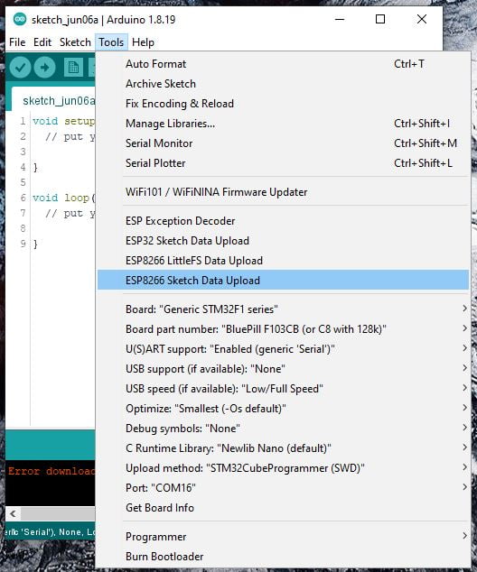
STM32 power saving: library LowPower, wiring, and Idle mode – 4
In a remote device, one important feature can be the power consumption, and like other devices, STM32 allows a set of Low Power states.
In this article, we look at the library to use and performance with our devices.
Here my selection of STM32 STM32F103C8T6 STM32F401 STM32F411 ST-Link v2 ST-Link v2 official
Library
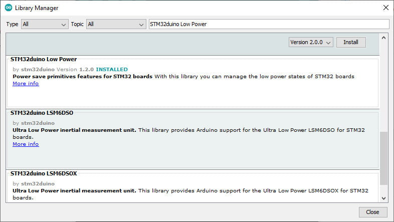
In the Arduino framework, we are going to use the STM32LowPower library, so the process becomes effortless.
You can find that library on the Arduino library manager.
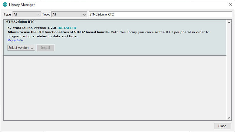
This library has dependencies also, including a library that we used in the article “STM32: internal RTC, clock and battery backup (VBAT)“, which is used to interface the internal RTC clock.
As usual, you can find It in the library manager.
API
void begin(): configure the Low Power;void idle(uint32_t ms): enter in idle mode;- ms (optional): the number of milliseconds before exiting the mode. The RTC is used in alarm mode to wake up the chip in ms milliseconds.
void sleep(uint32_t ms): enter in sleep mode;ms (optional): the number of milliseconds before exiting the mode. The RTC is used in alarm mode to wake up the chip in ms milliseconds.
void deepSleep(uint32_t ms): enter in deepSleep mode;ms (optional): the number of milliseconds before exiting the mode. The RTC is used in alarm mode to wake up the chip in ms milliseconds.
void shutdown(uint32_t ms): enter in shutdown mode;ms (optional): the number of milliseconds before exiting the mode. The RTC is used in alarm mode to wake up the board in ms milliseconds.
Note: With the STM32RTC version lower than 1.1.0, the minimum milliseconds is 1000 ms.
void attachInterruptWakeup(uint32_t pin, voidFuncPtrVoid callback, uint32_t mode, LP_Mode LowPowerMode): Enable GPIO pin in interrupt mode. If the pin is a wake-up pin, it is configured as a wake-up source (see board documentation).
param- pin: pin number
- callback: pointer to a callback
- mode: interrupt mode (HIGH, LOW, RISING, FALLING, or CHANGE)
- LowPowerMode: Low power mode which will be used (IDLE_MODE, SLEEP_MODE, DEEP_SLEEP_MODE or SHUTDOWN_MODE). In the case of SHUTDOWN_MODE only, the wake-up pin capability is activated.
void enableWakeupFrom(HardwareSerial *serial, voidFuncPtrVoid callback): enable a UART peripheral in low power mode. See board documentation for low power mode compatibility.- serial: pointer to a UART
- callback: pointer to a callback to call when the board is waked up.
void enableWakeupFrom(STM32RTC *rtc, voidFuncPtr callback, void * data): attach a callback to the RTC peripheral.- rtc: pointer to RTC. It could be NULL as RTC is a Singleton.
- callback: pointer to a callback to call when the board is waked up.
- data: optional pointer to callback data parameters (default NULL).
void enableWakeupFrom(TwoWire *wire, voidFuncPtrVoid callback): enable an I2C peripheral in low power mode. See board documentation for low power mode compatibility. Currently not available.- wire: pointer to I2C
- callback: pointer to a callback to call when the board is waked up.
Begin() function must be called at least once before idle(), sleep(), deepSleep() or shutdown() functions.
attachInterruptWakeup() or enableWakeupFrom() functions should be called before idle(), sleep(), deepSleep() or shutdown() functions.
HardwareSerial used as a wake-up source will configure it to use the HSI clock source even if another peripheral clock is configured.
RTC used as a wake-up source will configure it to use the LSE clock source even if another RTC clock source is selected.
The board will restart when it exits the deepSleep or shutdown mode.
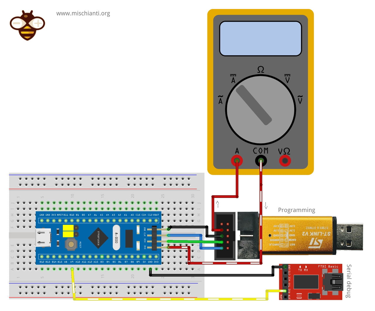
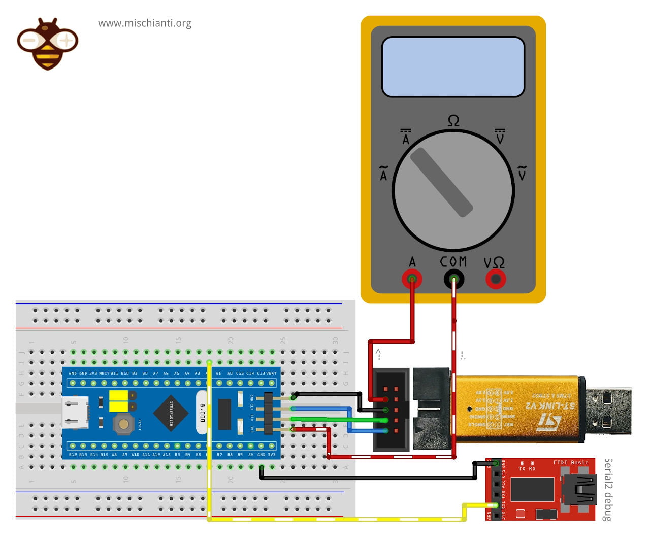
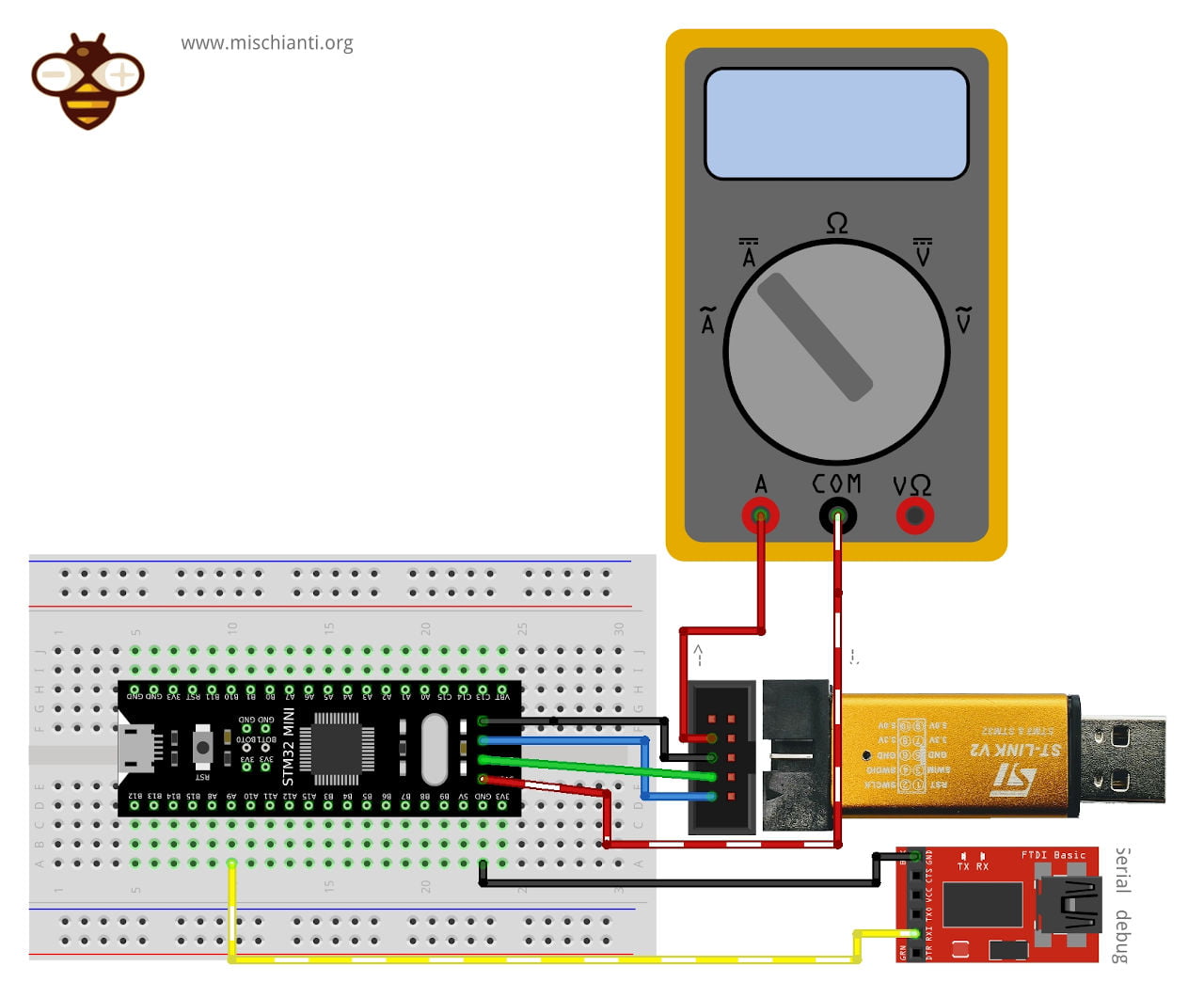
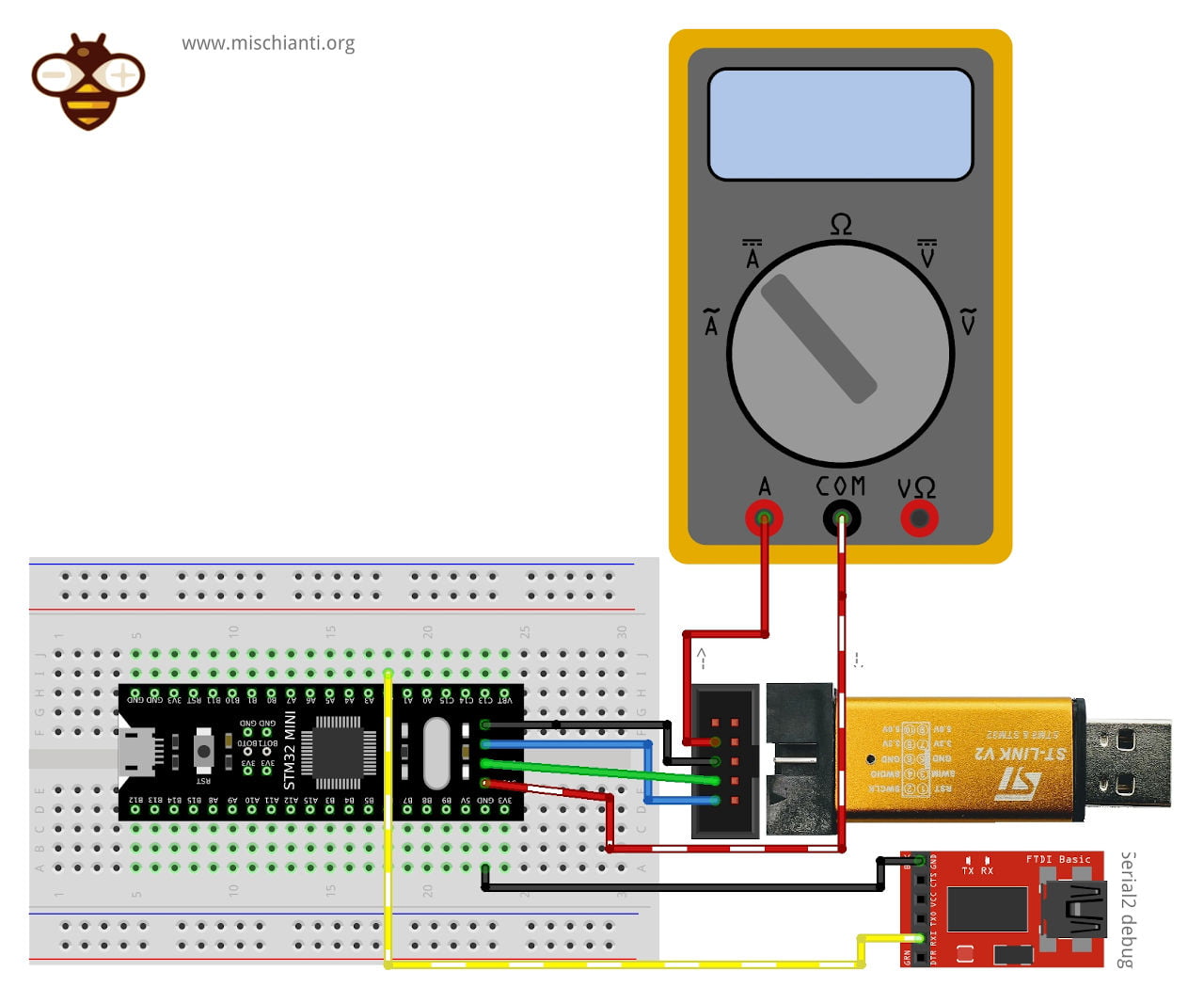
Wiring for our tests
We are going to use ST-Link to program and power the STM32, but we are going to put in the middle of the 3v3 pin of ST-Link V2 and 3.3v of the STM32 a multimeter to measure the amperage to analyze the power consumption.
Here the STM32 and ST-Link V2 used in this test STM32F103C8T6 STM32F401 STM32F411 ST-Link v2 ST-Link v2 official
Here the FTDI USB to TTL CH340G - USB to TTL FT232RL
Here my multimeter Aneng SZ18
To obtain the serial output, we use an external FTDI connected only to the GND and Tx pins of the STM32, which are then connected to the GND and Rx pins of the FTDI.
STM32F1 and Serial to debug
STM32F1 and Serial2 to debug
STM32F4 and Serial to debug
STM32F4 and Serial2 to debug
Wake up with internal interrupt managed by RTC
Now we are going to do some tests, first of all, we check the power consumption of all sleep statuses (idle, sleep, deepSleep, shutdown), and we use an internal interrupt managed by RTC to wake up the device.
In this article, we will only consider the “Idle” state, and in the upcoming articles, we will cover the remaining states.
For this test, you need the STM32LowPower library and STM32RTC library.
Idle
As described, Idle status is the Sleep on the ST framework. This state has a speedy wake-up time and stops the CPU.
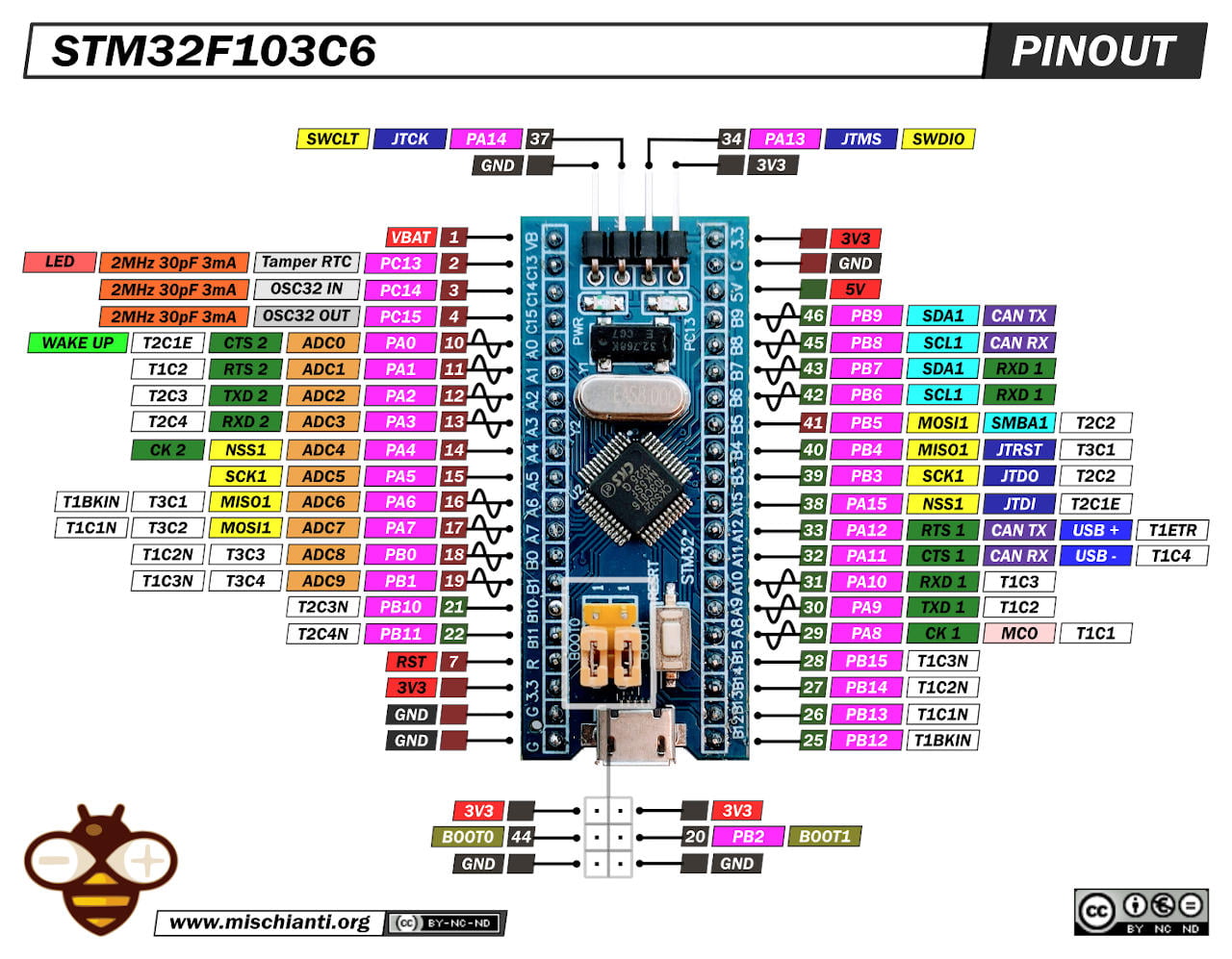
STM32F1
The first device we use is an STM32F103C8 blue pill.
/**
 *	STM32 Low Power IDLE wake up test from RTC
 *
 * 	This sketch demonstrates the usage of Internal Interrupts to wakeup a chip
 *	in idle mode.
 *
 *	In this sketch, the internal RTC will wake up the processor.
 *
 *	Renzo Mischianti <www.mischianti.org>
 * en: https://mischianti.org/category/tutorial/stm32-tutorial/
 * it: https://mischianti.org/it/category/guide/guida-alla-linea-di-microcontrollori-stm32/
 */

#include "STM32LowPower.h"

// If you use generic STM32F103C8
// you don't need this explicit declaration
// This is needed by bluepill specified version
//HardwareSerial Serial(USART2);   // PA3  (RX)  PA2  (TX)

void setup() {
	Serial.begin(115200);
	while (!Serial){ delay(100); }
	Serial.println("START!");

	// Configure low power
	LowPower.begin();
}

void loop() {
	Serial.print("Entering idle in ");
	for (int i=5; i>0; i--) {Serial.print(i);Serial.print(" ");delay(500);}
	Serial.println();
	delay(100); // Needed to give time to write the Serial
	LowPower.idle(5000); // Entering in idle

	delay(100); // Needed to restore the Serial
	Serial.print("Wake for 10 seconds! ");
	for (int i=10; i>0; i--) {Serial.print(i);Serial.print(" ");delay(1000);}
	Serial.println();
}
The output in the Serial is
Entering idle in 5 4 3 2 1
Wake for 10 seconds! 10 9 8 7 6 5 4 3 2 1
Entering idle in 5 4 3 2 1
Wake for 10 seconds! 10 9 8 7 6 5 4 3 2 1
Entering idle in 5 4 3 2 1
Wake for 10 seconds! 10 9 8 7 6 5 4 3 2 1
Entering idle in 5 4 3 2 1
Wake for 10 seconds! 10 9 8 7 6 5 4
When entering Idle, the power consumption from 17.50mAh goes down to 9.37mAh.
STM32F401
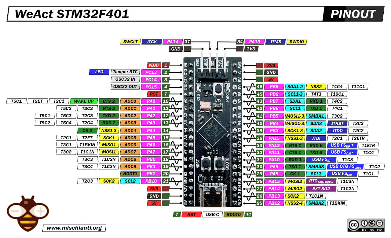
The same sketch in the STM32F401CC Black-Pill from 23.50mAh obtain a lower result for STM32F103, 7.55mAh.
STM32F411
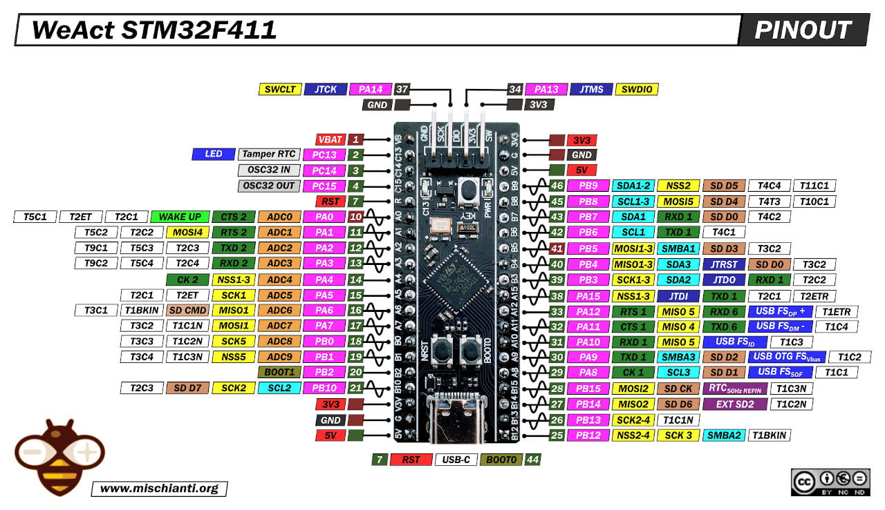
The same sketch in the STM32F411CE Black-Pill from 32.50mAh obtain a similar result for STM32F103, 11.05mAh.
Thanks
- STM32F1 Blue-Pill: pinout, specs, and Arduino IDE configuration (STM32duino and STMicroelectronics)
- STM32: program (STM32F1) via USB with STM32duino bootloader
- STM32: programming (STM32F1 STM32F4) via USB with HID boot-loader
- STM32F4 Black-Pill: pinout, specs, and Arduino IDE configuration
- STM32: ethernet w5500 with plain HTTP and SSL (HTTPS)
- STM32: ethernet enc28j60 with plain HTTP and SSL (HTTPS)
- STM32: WiFiNINA with ESP32 WiFi Co-Processor
- How to use SD card with stm32 and SdFat library
- \STM32: SPI flash memory FAT FS
- STM32: internal RTC, clock, and battery backup (VBAT)
- STM32 LoRa
- STM32 Power saving
- STM32F1 Blue-Pill clock and frequency management
- STM32F4 Black-Pill clock and frequency management
- Intro and Arduino vs STM framework
- Library LowPower, wiring, and Idle (STM Sleep) mode
- Sleep, deep sleep, shutdown, and power consumption
- Wake up from RTC alarm and Serial
- Wake up from the external source
- Backup domain intro and variable preservation across reset
- RTC backup register and SRAM preservation
- STM32 send emails with attachments and SSL (like Gmail): w5500, enc28j60, SD, and SPI Fash
- FTP server on STM32 with w5500, enc28j60, SD Card, and SPI Flash
- Connecting the EByte E70 to STM32 (black/blue pill) devices and a simple sketch example