STM32 power saving: backup domain intro and variable preservation across reset – 8
Another important element of STM32 is the backup domain, but after a brief introduction we are going to evaluate and test the standard solution for RESET, practically the use of variables in “noinit” and “persistent” memory area very interesting features. And for specified usage, we write some simple functions to check the features of our devices.
Variables, RTC register, and SRAM preservation
One of the most useful things you can need when using Low-Power functions is state preservation, and first of all, we are going to do a fast recap of the main Low-Power mode.
Devices feature four main low-power modes:
- Sleep mode
- Only the CPU clock is stopped.
The cortex-M clock is stopped and the peripherals are kept running. The current consumption increases with the clock frequency. As in Run mode, the user should be aware of system configuration rules that concern the system clock and voltage regulator scales.
- Only the CPU clock is stopped.
- Stop mode:
- Lowest power consumption while all the SRAM and registers are kept.
- The Cortex-M core is stopped. PLL, HSI, HSE are disabled.
- All I/O pins keep the same state as the Run mode.
- All clocks in 1.2V domain are switched-off.
- The main regulator and low-power regulator can be in normal mode or in underdrive mode.
- The Flash memory is working in Stop mode or Deep-power down mode to save more static power.
- Standby mode:
- This mode has the lowest current consumption.
- The Cortex-M core is stopped and the clocks are switched off.
- The 1.2 domain is powered off (regulator is disabled).
- The SRAM and registers contents are lost except for the registers in the backup domain (RTC registers, RTC backup register and backup SRAM) and standby circuitry.
- All I/O pins are high impedance except for:
- Reset pad
- PC13 if configured for tamper, time stamp, RTC Alarm out, or RTC clock
calibration out - WKUP pins (PA0/PA2/PC1/PC13/PI8/PI11), if enabled
- VBAT mode:
- This mode is used only when the main digital supply (VDD) is turned off.
- The circuit is supplied through VBAT pin which should be connected to an external supply voltage (a battery or any other source).
- The VBAT pin powers the backup domain (RTC registers, RTC backup register, and backup SRAM)
|
Mode name |
Entry |
Wakeup |
Effect on VCORE domain clocks |
Effect on VDD domain clocks |
Voltage regulator |
|
Low-power run |
LPSDSR and LPRUN bits + Clock setting |
The regulator is forced in Main regulator (1.8 V) |
None |
None |
In low-power mode |
|
Sleep (Sleep now or Sleep-on-exit) |
WFI |
Any interrupt |
CPU CLK OFF no effect on other clocks or analog clock sources |
None |
ON |
|
WFE |
Wakeup event |
||||
|
Low-power sleep (Sleep now or Sleep- on-exit) |
LPSDSR bits + WFI |
Any interrupt |
CPU CLK OFF no effect on other clocks or analog clock sources, Flash CLK OFF |
None |
In low-power mode |
|
LPSDSR bits + WFE |
Wakeup event |
||||
|
Stop |
PDDS, LPSDSR bits + SLEEPDEEP bit + WFI or WFE |
Any EXTI line (configured in the EXTI registers, internal and external lines) |
All VCORE domain clocks OFF |
HSI and HSE and MSI oscillators OFF |
In low-power mode |
|
Standby |
PDDS bit + SLEEPDEEP bit + WFI or WFE |
WKUP pin rising edge, RTC alarm (Alarm A or Alarm B), RTC Wakeup event, RTC tamper event, RTC timestamp event, external reset in NRST pin, IWDG reset |
OFF |
For Sleep and Stop (Idle and Sleep) the retention is quite simple, but if you want to use Standby (shutdown) to save data we must use the RTC register and SRAM memory.
In this scenario, you must understand how some parts interact with the system:
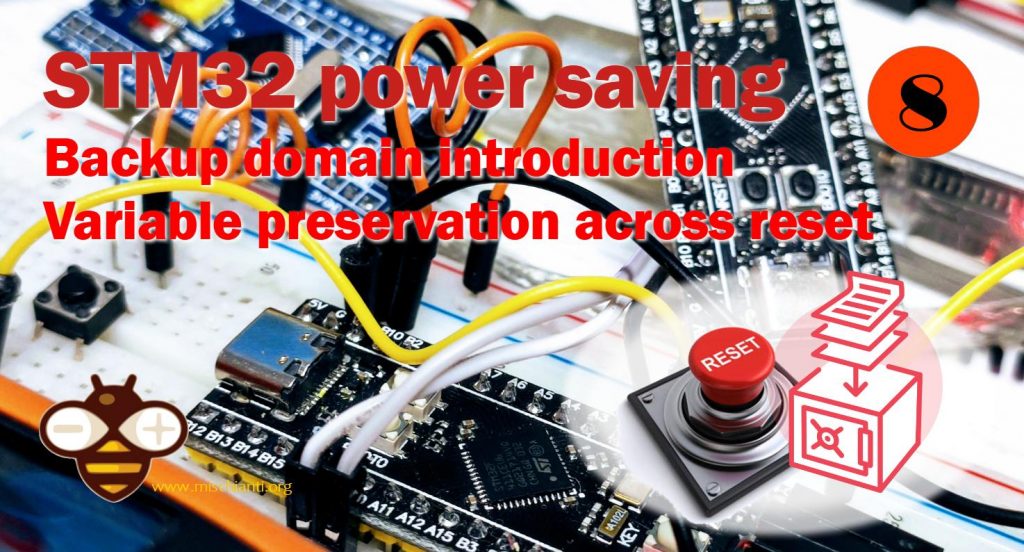
Voltage Regulator
The voltage regulator is always enabled after Reset and works in three different modes depending on the application modes:
- Run mode: the regulator supplies full power to the 1.8 V domain (core, memories, and digital peripherals)
- Stop mode: the regulator supplies low-power to the 1.8 V domain, preserving the contents of registers and SRAM
- Standby Mode: the regulator is powered off. The contents of the registers and SRAM are lost except for the Standby circuitry and the Backup Domain
Battery Backup Domain
To retain the content of the Backup registers and supply the RTC function when VDD is turned off, VBAT pin can be connected to an optional standby voltage supplied by a battery or by another source.
The VBAT pin powers the RTC unit, the LSE oscillator, and the PC13 to PC15 IOs, allowing the RTC to operate even when the main digital supply (VDD) is turned off.
The switch to the VBAT supply is controlled by the Power Down Reset embedded in the Reset block
Backup Registers (BKP)
- Backup registers are ten 16-bit registers in low and medium-density devices for storing 20 bytes of user application data
- They are implemented in the backup domain that remains powered on by VBAT when the VDD power is switched off.
- They are not reset when the device wakes up from Standby mode or by a system reset or power reset
- In addition, the BKP control registers are used to manage the Tamper detection feature and RTC calibration.
- After reset, access to the Backup registers and RTC is disabled and the Backup domain (BKP) is protected against possible parasitic write access
- To enable access to the Backup registers and the RTC, proceed as follows:
- Enable the power and backup interface clocks by setting the PWREN and BKPEN bits in the RCC_APB1ENR register
- Set the DBP bit to the Power Control Register (PWR_CR) to enable access to the Backup registers and RTC.
And can be useful to understand the different reset systems:
System Reset
- A system reset sets all registers to their reset values except the reset flags in the clock controller CSR register and the registers in the Backup domain
- A system reset is generated when one of the following events occurs:
- Low level on the NRST pin (external reset)
- Window watchdog end of count condition (WWDG reset)
- Independent watchdog end of count condition (IWDG reset)
- Software reset (SW reset)
- Low-power management reset
- Software reset
- The SYSRESETREQ bit in Cortex™-M3 Application Interrupt and Reset Control Register must be set to force a software reset on the device
- Low-power management reset:
- Method 1: Reset generated when entering Standby mode: This type of reset is enabled by resetting nRST_STDBY bit in User Option Bytes. In this case, whenever a Standby mode entry sequence is successfully executed, the device is reset instead of entering Standby mode.
- Method 2: Reset when entering Stop mode: This type of reset is enabled by resetting NRST_STOP bit in User Option Bytes. In this case, whenever a Stop mode entry sequence is successfully executed, the device is reset instead of entering Stop mode.
Power Reset
- A power reset is generated when one of the following occurs:
- Power-on/power-down reset (POR/PDR reset)
- When exiting Standby mode
- A power reset sets all registers to their reset values except the Backup domain
- These sources act on the NRST pin and it is always kept low during the delay phase. The
- RESET vector is fixed at address 0x00000004 in the memory map
Backup Domain Reset
- The backup domain has two specific resets that affect only the backup domain
- A backup domain reset is generated when one of the following events occurs:
- Software reset, triggered by setting the BDRST bit in the Backup domain control register (RCC_BDCR)
- VDD or VBAT power on, if both have previously been powered off
Now we can start to do some tests.
Identify the reset type
So there are some reset types and for our test can be useful to understand how to recognize Them. I use the Low-Power sketch (check the relative article if you don’t understand some parts) and I add 2 functions that identify the reset source and which clocks are ready.
/**
 * I add to a simple sketch
 * that set the time to 2022-04-20 at 16:00:00 and an alarm at 16:00:10 wake-up after 10 secs
 * 2 function that identify the reset source and witch clocks are ready
  *
 * Renzo Mischianti <www.mischianti.org>
 * en: https://mischianti.org/category/tutorial/stm32-tutorial/
 * it: https://mischianti.org/it/category/guide/guida-alla-linea-di-microcontrollori-stm32/
 */

#include "STM32LowPower.h"
#include <STM32RTC.h>

// Pin used to trigger a wakeup
#ifndef USER_BTN
#define USER_BTN SYS_WKUP1
#endif

const int pin = USER_BTN;

/* Get the rtc object */
STM32RTC& rtc = STM32RTC::getInstance();

/* Change these values to set the current initial time */
const byte seconds = 0;
const byte minutes = 0;
const byte hours = 16;

/* Change these values to set the current initial date */
const byte day = 20;
const byte month = 4;
const byte year = 22;

void wakedUp();
void alarmMatch(void *data);
void printWakeSource();
void printClockReady();

void setup()
{
  Serial.begin(115200);
  pinMode(pin, INPUT_PULLUP);

  printWakeSource();
  printClockReady();

  __HAL_RCC_CLEAR_RESET_FLAGS();

  // Select RTC clock source: LSI_CLOCK, LSE_CLOCK or HSE_CLOCK.
  // By default the LSI is selected as source.
//  rtc.setClockSource(STM32RTC::LSI_CLOCK);

  rtc.begin(); // initialize RTC 24H format
  // we set the time at 2022-04-20 at 16:00:00
  rtc.setTime(hours, minutes, seconds);
  rtc.setDate(day, month, year);

  delay(1000);


  String someRandomData = "www.mischianti.org";

  // Configure low power
  LowPower.begin();
  // Attach a wakeup interrupt on pin, calling repetitionsIncrease when the device is woken up
  // Last parameter (LowPowerMode) should match with the low power state used: in this example LowPower.sleep()
//  LowPower.attachInterruptWakeup(pin, wakedUp, RISING, SHUTDOWN_MODE);

  LowPower.enableWakeupFrom(&rtc, alarmMatch, &someRandomData);

  // Now we set an alert at 16:00:10
  // pratically 10 secs after the start
  // (check the initialization of clock)
  rtc.setAlarmDay(day);
  rtc.setAlarmTime(16, 0, 10, 0);
  rtc.enableAlarm(rtc.MATCH_DHHMMSS);

  // Print date...
  Serial.printf("Now is %02d/%02d/%02d %02d:%02d:%02d.%03d and we set the wake at 16:10! So wait 10secs! \n",
		  rtc.getDay(), rtc.getMonth(), rtc.getYear(),
		  rtc.getHours(), rtc.getMinutes(), rtc.getSeconds(), rtc.getSubSeconds());

  delay(1000);

  LowPower.shutdown();

}

void loop()
{
  // Print date...
  Serial.printf("%02d/%02d/%02d ", rtc.getDay(), rtc.getMonth(), rtc.getYear());

  // ...and time
  Serial.printf("%02d:%02d:%02d.%03d\n", rtc.getHours(), rtc.getMinutes(), rtc.getSeconds(), rtc.getSubSeconds());
  delay(1000);
}

void alarmMatch(void *data)
{
	String myData = *(String*)data;
	Serial.println("Alarm Match!");
	Serial.println(myData);
}

void wakedUp() {
  // This function will be called once on device wakeup
  // You can do some little operations here (like changing variables which will be used in the loop)
  // Remember to avoid calling delay() and long running functions since this functions executes in interrupt context
	Serial.println("Wake UP pin!");
}

void printClockReady() {
	Serial.println(F("--------- CLOCK Ready -------------"));
	if (__HAL_RCC_GET_FLAG(RCC_FLAG_HSIRDY)) {
	    Serial.println(F("HSI oscillator clock ready."));
	}
	if (__HAL_RCC_GET_FLAG(RCC_FLAG_HSERDY)) {
	    Serial.println(F("HSE oscillator clock ready."));
	}
	if (__HAL_RCC_GET_FLAG(RCC_FLAG_PLLRDY)) {
	    Serial.println(F("Main PLL clock ready."));
	}
	if (__HAL_RCC_GET_FLAG(RCC_FLAG_PLLI2SRDY)) {
	    Serial.println(F("PLLI2S clock ready."));
	}
	if (__HAL_RCC_GET_FLAG(RCC_FLAG_LSERDY)) {
	    Serial.println(F("LSE oscillator clock ready."));
	}
	if (__HAL_RCC_GET_FLAG(RCC_FLAG_LSIRDY)) {
	    Serial.println(F("LSI oscillator clock ready."));
	}
	Serial.println(F("-----------------------------------"));
}

void printWakeSource() {
	Serial.println(F("--------- RESET   Source ----------"));
	if (__HAL_RCC_GET_FLAG(RCC_FLAG_BORRST)) {
	    Serial.println(F("Wake from POR/PDR or BOR reset."));
	}
	if (__HAL_RCC_GET_FLAG(RCC_FLAG_PINRST)) {
	    Serial.println(F("Wake from Pin reset."));
	}
	if (__HAL_RCC_GET_FLAG(RCC_FLAG_PORRST)) {
	    Serial.println(F("Wake from POR/PDR reset."));
	}
	if (__HAL_RCC_GET_FLAG(RCC_FLAG_SFTRST)) {
	    Serial.println(F("Wake from Software reset."));
	}
	if (__HAL_RCC_GET_FLAG(RCC_FLAG_IWDGRST)) {
	    Serial.println(F("Wake from Independent Watchdog reset."));
	}
	if (__HAL_RCC_GET_FLAG(RCC_FLAG_WWDGRST)) {
	    Serial.println(F("Wake from Window Watchdog reset."));
	}
	if (__HAL_RCC_GET_FLAG(RCC_FLAG_LPWRRST)) {
	    Serial.println(F("Wake from Low Power reset."));
	}
	Serial.println(F("-----------------------------------"));
}
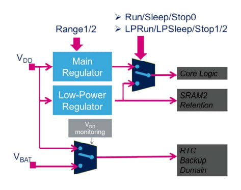
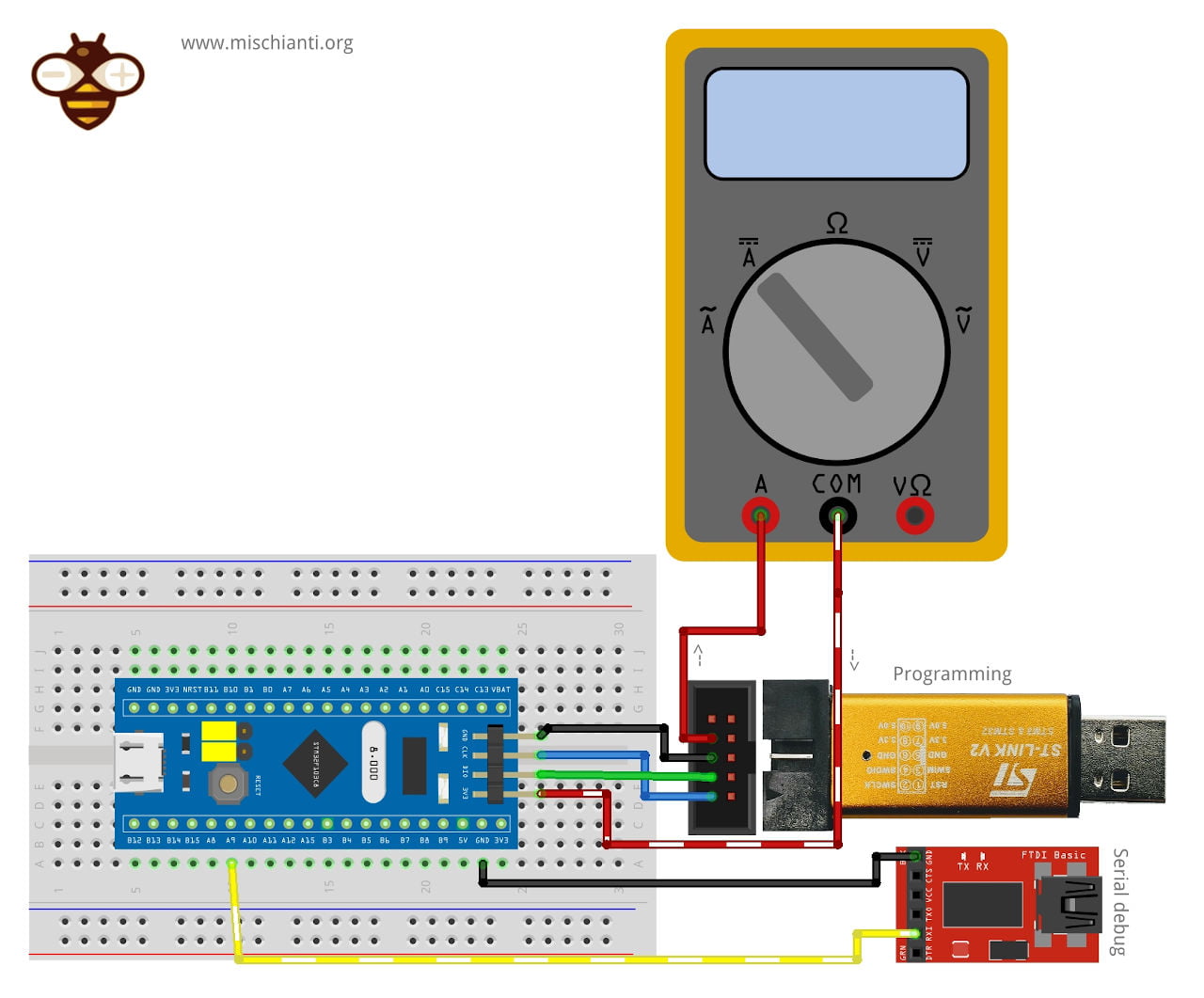
I advise doing this wiring so you can attach the serial monitor to the FTDI and get all Serial messages.
Here the STM32 and ST-Link V2 used in this test STM32F103C8T6 STM32F401 STM32F411 ST-Link v2 ST-Link v2 official
Here the FTDI USB to TTL CH340G - USB to TTL FT232RL
Here my multimeter Aneng SZ18
Software reset
Now when you upload the code you get this output.
--------- RESET   Source ----------
Wake from Pin reset.
Wake from Software reset.
-----------------------------------
--------- CLOCK Ready -------------
HSI oscillator clock ready.
HSE oscillator clock ready.
Main PLL clock ready.
-----------------------------------
Now is 20/04/22 16:00:00.944 and we set the wake at 16:10! So wait 10secs!
Wake-up interrupt
When the device is waked up from shutdown you get:
--------- RESET   Source ----------
-----------------------------------
--------- CLOCK Ready -------------
HSI oscillator clock ready.
HSE oscillator clock ready.
Main PLL clock ready.
LSI oscillator clock ready.
-----------------------------------
Now is 20/04/22 16:00:00.944 and we set the wake at 16:10! So wait 10secs!
So nothing information about that.
RESET button
If you click on RESET button (reset pin) you obtain this result.
--------- RESET   Source ----------
Wake from Pin reset.
-----------------------------------
--------- CLOCK Ready -------------
HSI oscillator clock ready.
HSE oscillator clock ready.
Main PLL clock ready.
-----------------------------------
Now is 20/04/22 16:00:00.940 and we set the wake at 16:10! So wait 10secs!
In this case, use a reset pin but non activated via software like the previous situation (when uploading the code).
Disconnect from the power supply
Now the last interesting test is to remove the device from the power supply, the result is this.
--------- RESET   Source ----------
Wake from POR/PDR or BOR reset.
Wake from Pin reset.
Wake from POR/PDR reset.
-----------------------------------
--------- CLOCK Ready -------------
HSI oscillator clock ready.
HSE oscillator clock ready.
Main PLL clock ready.
-----------------------------------
Now is 20/04/22 16:00:00.944 and we set the wake at 16:10! So wait 10secs!
Preserve variable value across RESET
Before starting to analyze the RTC register and SRAM, I’d like to show some systems to preserve value across RESET.
We can use the attribute __attribute__((__section__(".noinit"))); and __attribute__((__section__(".persistent"))); this simple attribute moves the stored position of the variable in a “noinit” and “persistent” section.
But you can understand the behavior with this simple sketch:
/**
 * A simple sketch to evaluate noinit and persistent variable pragma
 *
 * Renzo Mischianti <www.mischianti.org>
 * https://mischianti.org
 *
 */

unsigned boot_count __attribute__((__section__(".noinit")));
unsigned boot_count_persistent __attribute__((section(".persistent")));

void setup()
{
  Serial.begin(115200);
  delay(1000);

  // Initialize the variable only on first power-on reset
  if (__HAL_RCC_GET_FLAG(RCC_FLAG_BORRST)) {
      boot_count = 0;
      boot_count_persistent = 0;
      Serial.println("START: First boot!");
  } else {
	  Serial.println("START!");
  }
  __HAL_RCC_CLEAR_RESET_FLAGS();

  Serial.print("Boot number: ");
  Serial.println(boot_count);
  boot_count = boot_count + 1;

  Serial.print("Boot number persistent: ");
  Serial.println(boot_count_persistent);
  boot_count_persistent = boot_count_persistent + 1;
}

void loop()
{
  delay(1000);
}
Here It’s the serial output:
START!
Boot number: 4122089554
Boot number persistent: 587262422
START: First boot!
Boot number: 0
Boot number persistent: 0
START!
Boot number: 1
Boot number persistent: 1
START!
Boot number: 2
Boot number persistent: 2
START!
Boot number: 3
Boot number persistent: 3
START!
Boot number: 4
Boot number persistent: 4
At the first start It loads the memory value of initialized variables, at line 4 I disconnect the power, and when I reconnect It I intercept the first boot and I reset the value of the variable.
  // Initialize the variable only on first power-on reset
  if (__HAL_RCC_GET_FLAG(RCC_FLAG_BORRST)) {
      boot_count = 0;
      boot_count_persistent = 0;
      Serial.println("START: First boot!");
  } else {
	  Serial.println("START!");
  }
Now every time I click on reset (when START! the string is printed) the code shows me the current value of the variable.
But what happened if I try to use this system with a shutdown.
/**
 * A simple sketch that set the time to
 * 2022-04-20 at 16:00:00
 * and an alarm at
 * 16:00:20
 * the result is the interrupt after 10 secs
 *
 * I initialize the variables in noinit and persistent area, if
 * you click the reset button the values are persisted but on shutdown/standby
 * the values are losts
 *
 * Renzo Mischianti <www.mischianti.org>
 * https://mischianti.org
 *
 */

unsigned boot_count __attribute__((__section__(".noinit")));
unsigned boot_count_persistent __attribute__((section(".persistent")));

#include "STM32LowPower.h"
#include <STM32RTC.h>

/* Get the rtc object */
STM32RTC& rtc = STM32RTC::getInstance();

/* Change these values to set the current initial time */
const byte seconds = 0;
const byte minutes = 0;
const byte hours = 16;

/* Change these values to set the current initial date */
const byte day = 20;
const byte month = 4;
const byte year = 22;

void alarmMatch(void *data);
void printWakeSource();

void setup()
{
  Serial.begin(115200);

  printWakeSource();

  // Initialize the variable only on first power-on reset
  if (__HAL_RCC_GET_FLAG(RCC_FLAG_BORRST)) {
      boot_count = 0;
      boot_count_persistent = 0;
  }
  __HAL_RCC_CLEAR_RESET_FLAGS();

  // Select RTC clock source: LSI_CLOCK, LSE_CLOCK or HSE_CLOCK.
  // By default the LSI is selected as source.
//  rtc.setClockSource(STM32RTC::LSI_CLOCK);

  rtc.begin(); // initialize RTC 24H format
  // we set the time at 2022-04-20 at 16:00:00
  rtc.setTime(hours, minutes, seconds);
  rtc.setDate(day, month, year);

  delay(1000);


  String someRandomData = "www.mischianti.org";

  // Configure low power
  LowPower.begin();
  LowPower.enableWakeupFrom(&rtc, alarmMatch, &someRandomData);

  int wakeSeconds = rtc.getSeconds()+20;
  // Now we set an alert at 16:00:10
  // pratically 10 secs after the start
  // (check the initialization of clock)
  rtc.setAlarmDay(day);
  rtc.setAlarmTime(16, 0, wakeSeconds, 0);
  rtc.enableAlarm(rtc.MATCH_DHHMMSS);

  Serial.print("Boot number: ");
  Serial.println(boot_count);
  boot_count = boot_count + 1;

  Serial.print("Boot number persistent: ");
  Serial.println(boot_count_persistent);
  boot_count_persistent = boot_count_persistent + 1;

  Serial.println("Start shutdown mode in ");
  for (int i = 10;i>0;i--) { Serial.print(i); Serial.print(" "); delay(1000); } Serial.println( "OK!" );

  // Print date...
  Serial.printf("Now is %02d/%02d/%02d %02d:%02d:%02d.%03d and we set the wake at 16:%02d! So wait 10secs! \n",
		  rtc.getDay(), rtc.getMonth(), rtc.getYear(),
		  rtc.getHours(), rtc.getMinutes(), rtc.getSeconds(), rtc.getSubSeconds(), wakeSeconds);
  delay(1000);

  LowPower.shutdown();
}

void loop()
{
  // Print date...
  Serial.printf("%02d/%02d/%02d ", rtc.getDay(), rtc.getMonth(), rtc.getYear());

  // ...and time
  Serial.printf("%02d:%02d:%02d.%03d\n", rtc.getHours(), rtc.getMinutes(), rtc.getSeconds(), rtc.getSubSeconds());
  delay(1000);
}

void alarmMatch(void *data)
{
	String myData = *(String*)data;
	Serial.println("Alarm Match!");
	Serial.println(myData);
}

void printWakeSource() {
	Serial.println(F("-----------------------------------"));
	if (__HAL_RCC_GET_FLAG(RCC_FLAG_BORRST)) {
	    Serial.println(F("Wake from POR/PDR or BOR reset."));
	}
	if (__HAL_RCC_GET_FLAG(RCC_FLAG_PINRST)) {
	    Serial.println(F("Wake from Pin reset."));
	}
	if (__HAL_RCC_GET_FLAG(RCC_FLAG_PORRST)) {
	    Serial.println(F("Wake from POR/PDR reset."));
	}
	if (__HAL_RCC_GET_FLAG(RCC_FLAG_SFTRST)) {
	    Serial.println(F("Wake from Software reset."));
	}
	if (__HAL_RCC_GET_FLAG(RCC_FLAG_IWDGRST)) {
	    Serial.println(F("Wake from Independent Watchdog reset."));
	}
	if (__HAL_RCC_GET_FLAG(RCC_FLAG_WWDGRST)) {
	    Serial.println(F("Wake from Window Watchdog reset."));
	}
	if (__HAL_RCC_GET_FLAG(RCC_FLAG_LPWRRST)) {
	    Serial.println(F("Wake from Low Power reset."));
	}
	Serial.println(F("-----------------------------------"));
}
The result is in this serial output:
-----------------------------------
Wake from POR/PDR or BOR reset.
Wake from Pin reset.
Wake from POR/PDR reset.
-----------------------------------
Boot number: 0
Boot number persistent: 0
Start shutdown mode in
10 9 8 -----------------------------------
Wake from Pin reset.
-----------------------------------
Boot number: 1
Boot number persistent: 1
Start shutdown mode in
10 9 8 7 6 5 4 3 2 1 OK!
Now is 20/04/22 16:00:10.396 and we set the wake at 16:20! So wait 10secs!
-----------------------------------
-----------------------------------
Boot number: 3475117321
Boot number persistent: 1065079675
Start shutdown mode in
10 9 8 7 6
You can see that the first time I press the reset button, and then I wait for the shutdown. Shutdown power off and cut all non backup areas so you lost the value of the variable.
Thanks
- STM32F1 Blue-Pill: pinout, specs, and Arduino IDE configuration (STM32duino and STMicroelectronics)
- STM32: program (STM32F1) via USB with STM32duino bootloader
- STM32: programming (STM32F1 STM32F4) via USB with HID boot-loader
- STM32F4 Black-Pill: pinout, specs, and Arduino IDE configuration
- STM32: ethernet w5500 with plain HTTP and SSL (HTTPS)
- STM32: ethernet enc28j60 with plain HTTP and SSL (HTTPS)
- STM32: WiFiNINA with ESP32 WiFi Co-Processor
- How to use SD card with stm32 and SdFat library
- \STM32: SPI flash memory FAT FS
- STM32: internal RTC, clock, and battery backup (VBAT)
- STM32 LoRa
- STM32 Power saving
- STM32F1 Blue-Pill clock and frequency management
- STM32F4 Black-Pill clock and frequency management
- Intro and Arduino vs STM framework
- Library LowPower, wiring, and Idle (STM Sleep) mode
- Sleep, deep sleep, shutdown, and power consumption
- Wake up from RTC alarm and Serial
- Wake up from the external source
- Backup domain intro and variable preservation across reset
- RTC backup register and SRAM preservation
- STM32 send emails with attachments and SSL (like Gmail): w5500, enc28j60, SD, and SPI Fash
- FTP server on STM32 with w5500, enc28j60, SD Card, and SPI Flash
- Connecting the EByte E70 to STM32 (black/blue pill) devices and a simple sketch example