STM32 power saving: intro and Arduino vs STM framework – 3
In a remote device, one important feature can be the power consumption, and like other devices, STM32 allows a set of Low Power states.
In the Arduino framework, these states are wrapped and simplified to allow the most straightforward management, but we will look at the original state of STM32 to better understand the test results.
Low-Power Modes in the Arduino framework

The STM32LowPower library that we are going to use identify four kinds of LowPower mode:
- Idle mode: low wake-up latency (µs range) (e.g., ARM WFI). Minimal power-saving mainly on the core itself. Memories and voltage supplies are retained.
- Sleep mode: low wake-up latency (µs range) (e.g., ARM WFI), Memories, and voltage supplies are retained. Minimal power-saving mainly on the core itself but higher than idle mode.
- Deep sleep mode: medium latency (ms range), clocks are gated to reduced. Memories and voltage supplies are retained. If supported, Peripherals wake-up is possible (UART, I2C …).
- Shutdown mode: high wake-up latency (possible hundreds of ms or second timeframe), voltage supplies are cut except the always-on domain, memory content is lost, and the system reboots.
Low-Power Modes in the STM framework
The STM32 devices implement five low-power modes: Low-power run mode, Sleep mode, Low-power sleep mode, Stop mode, and Standby mode. The differences between these modes can be described in terms of power consumption, performance, wake-up time, and wake-up sources. If the modes are put in order for each of these parameters, from best (1) to worst (5), it becomes clear what the trade-offs are. Generally speaking, as power consumption goes down, the performance decreases, the wake-up time increases, and the number of wake-up sources decreases. Table 1 summarizes the ranking of the low-power modes. As an example of interpretation, consider Low-power run mode. It has the best performance, the most wake-up sources, the second-fastest wake-up time, and the fourth-lowest current consumption.
| Performance | 1 | 2 | 3 | 4 | 5 |
|---|---|---|---|---|---|
| Power Consumption | 4 | 5 | 3 | 2 | 1 |
| Wake-up Time | 2 | 1 | 4 | 3 | 5 |
| Wake-up Sources | 1 | 2 | 3 | 4 | 5 |
Throughout this section, it will become clear how these rankings were derived. However, it is important to realize that they are only true in the general sense. For example, it is entirely possible for Stop mode to consume more current than Low-power sleep mode, depending on their configurations and which peripherals are enabled/disabled. But generally, this will not be the case because Stop mode restricts the device’s capabilities far more than Low-power sleep mode does to conserve more power. (from DigiKey forum)
Run Mode
This is the standard mode.
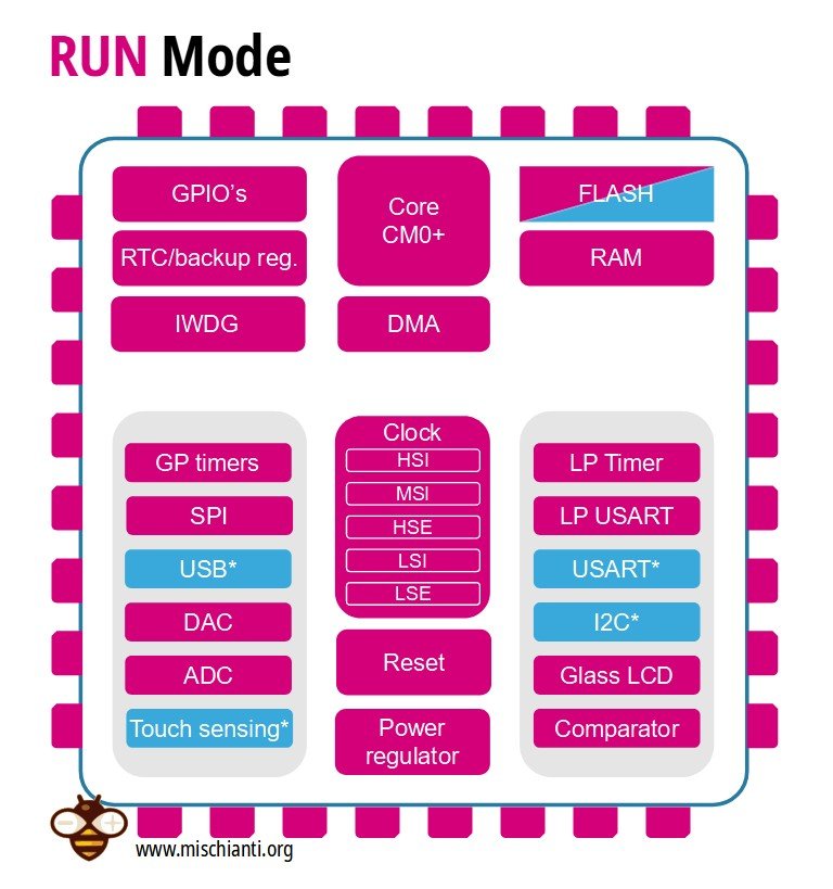
- Everything can be ON
- Any peripheral clocks can be gated (* examples)
- After resetting the peripherals clock are disabled
- Code can RUN from RAM and FLASH be OFF
Low-Power Run Mode
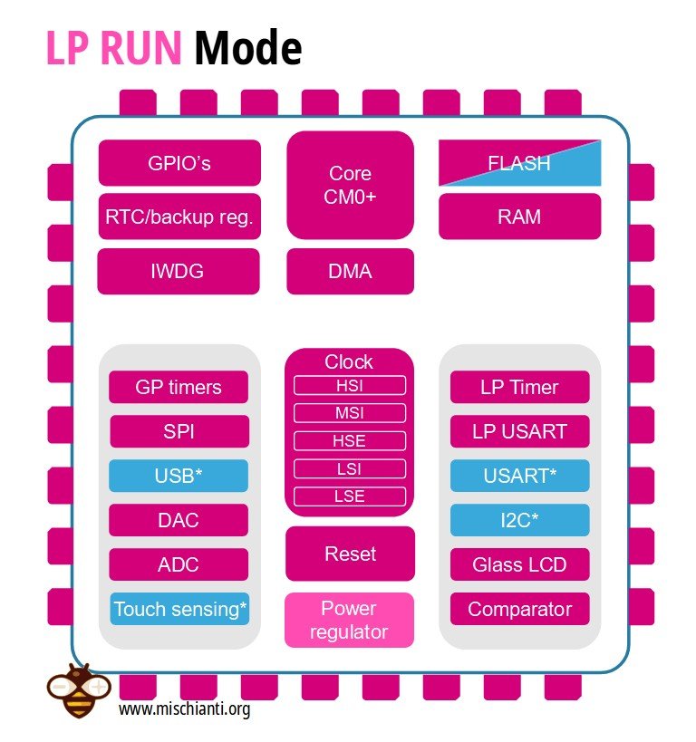
- Everything can be ON
- Any peripheral clocks can be gated (* examples)
- After resetting the peripherals clock is disabled
- The power regulator switched to Low Power mode
This mode is achieved with the multispeed internal (MSI) RC oscillator set to the low-speed clock, execution from SRAM or Flash memory, and internal regulator in low-power mode to minimize the regulator’s operating current. In Low-power run mode, the clock frequency and the number of enabled peripherals are both limited.
But reducing the clock speed of any microcontroller to the kilohertz range will dramatically reduce current consumption to the point of being competitive with the average sleep mode. This is not typically done, though, because the reduction in performance and the static current consumption (which is not dependent on the clock frequency) can use more energy in the long run. Depending on the application, i.e., which sleep mode is being used or how often the device wakes up, it may be more efficient to consume more current for a shorter period rather than consume less current for a more extended period. ST can get away with classifying this as a low-power mode because they provide the ability to put the internal voltage regulator into a low-power state.
Sleep Mode
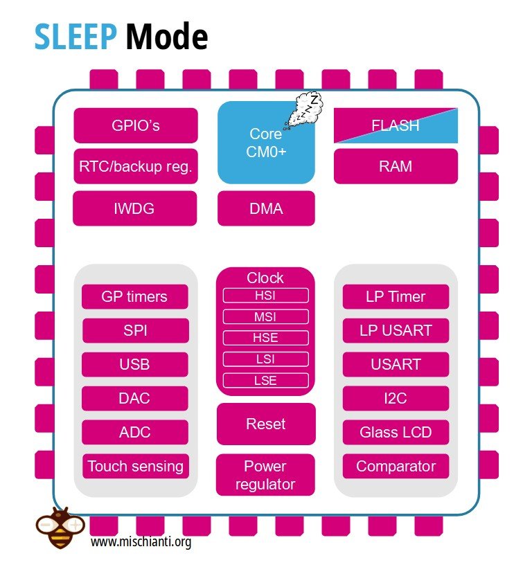
- Core is stopped
- Peripherals are running
Sleep mode allows all peripherals to be used and features the fastest wake-up time.
In these modes, the CPU is stopped, and each peripheral clock can be configured by software to be gated ON or OFF during the Sleep and Low-power sleep modes. These modes are entered by executing the assembler instruction Wait for Interrupt or Wait for Event. However, the wake-up time is almost ten times faster than the most competitive low-power mode. You can check the last row of this table to compare the wake-up time.
| Ips | Run/Active | Sleep | Low-power run | Low-power sleep | Stop | Stop W.C. | Standby | Standby W.C. |
|---|---|---|---|---|---|---|---|---|
| CPU | Y | — | Y | — | — | — | ||
| Flash memory | O | O | O | O | — | — | ||
| RAM | Y | Y | Y | Y | Y | — | ||
| Backup registers | Y | Y | Y | Y | Y | Y | ||
| EEPROM | O | O | O | O | — | — | ||
| Brown-out reset (BOR) | O | O | O | O | O | O | O | O |
| DMA | O | O | O | O | — | — | ||
| Programmable Voltage Detector (PVD) | O | O | O | O | O | O | – | |
| Power-on/down reset (POR/PDR) | Y | Y | Y | Y | Y | Y | Y | Y |
| High-Speed Internal (HSI) | O | O | — | — | (2) | — | ||
| High-Speed External (HSE) | O | O | O | O | — | — | ||
| Low-Speed Internal (LSI) | O | O | O | O | O | O | ||
| Low-Speed External (LSE) | O | O | O | O | O | O | ||
| Multi-Speed Internal (MSI) | O | O | Y | Y | — | — | ||
| Inter-Connect Controller | Y | Y | Y | Y | Y | — | ||
| RTC | O | O | O | O | O | O | O | |
| RTC Tamper | O | O | O | O | O | O | O | O |
| Auto WakeUp (AWU) | O | O | O | O | O | O | O | O |
| LCD | O | O | O | O | O | — | ||
| USB | O | O | — | — | — | O | — | |
| USART | O | O | O | O | O(3) | O | — | |
| LPUART | O | O | O | O | O(3) | O | — | |
| SPI | O | O | O | O | — | — | ||
| I2C | O | O | — | — | O(4) | O | — | |
| ADC | O | O | — | — | — | — | ||
| DAC | O | O | O | O | O | — | ||
| Temperature sensor | O | O | O | O | O | — | ||
| Comparators | O | O | O | O | O | O | — | |
| 16-bit timers | O | O | O | O | — | — | ||
| LPTIMER | O | O | O | O | O | O | ||
| IWDG | O | O | O | O | O | O | O | O |
| WWDG | O | O | O | O | — | — | ||
| Touch sensing controller (TSC) | O | O | — | — | — | — | ||
| SysTick timer | O | O | O | O | — | |||
| GPIOs | O | O | O | O | O | O | 2 pins | |
| Wakeup time to Run mode | 0µs | 0.36µs | 3µs | 32µs | 3.5µs | 3.5µs | 50µs | 50µs |
Legend:
- “Y” = Yes (enable).
“O” = Optional can be enabled/disabled by software)
“-” = Not available - Some peripherals with wake-up from Stop capability can request HSI to be enabled. In this case, HSI is woken up by the peripheral and only feeds the peripheral which requested it. HSI is automatically put off when the peripheral does not need it anymore.
- UART and LPUART reception is functional in Stop mode. It generates a wake-up interrupt on Start. To generate a wake-up on address match or received frame event, the LPUART can run on the LSE clock while the UART has to wake up or keep running the HSI clock.
- I2C address detection is functional in Stop mode. It generates a wake-up interrupt in case of an address match. It will wake up the HSI during the reception.
Sleep mode is wrapped with Idle mode in the STM32LowPower library
This makes it practically effortless to enter Sleep mode because the system frequency does not have to be decreased, and all of the device’s peripherals are available for use. Also, it is elementary to exit Sleep mode since any interrupt or event available in Run mode can wake the device and be serviced with very low latency.
Idle mode for Arduino framework
The library for Arduino framework STM32LowPowerMode calls this mode idle. And as you can see in the code,
/**
  * @brief  Enable the idle low power mode (STM32 sleep). Exit this mode on
  *         interrupt or in n milliseconds.
  * @param  ms: optional delay before leave the idle mode (default: 0).
  * @retval None
  */
void STM32LowPower::idle(uint32_t ms)
{
  if ((ms != 0) || _rtc_wakeup) {
    programRtcWakeUp(ms, IDLE_MODE);
  }
  LowPower_sleep(PWR_MAINREGULATOR_ON);
}
the state is reached by a LowPower_sleep with the flag PWR_MAINREGULATOR_ON that puts the primary voltage regulator on.
Low-Power Sleep Mode
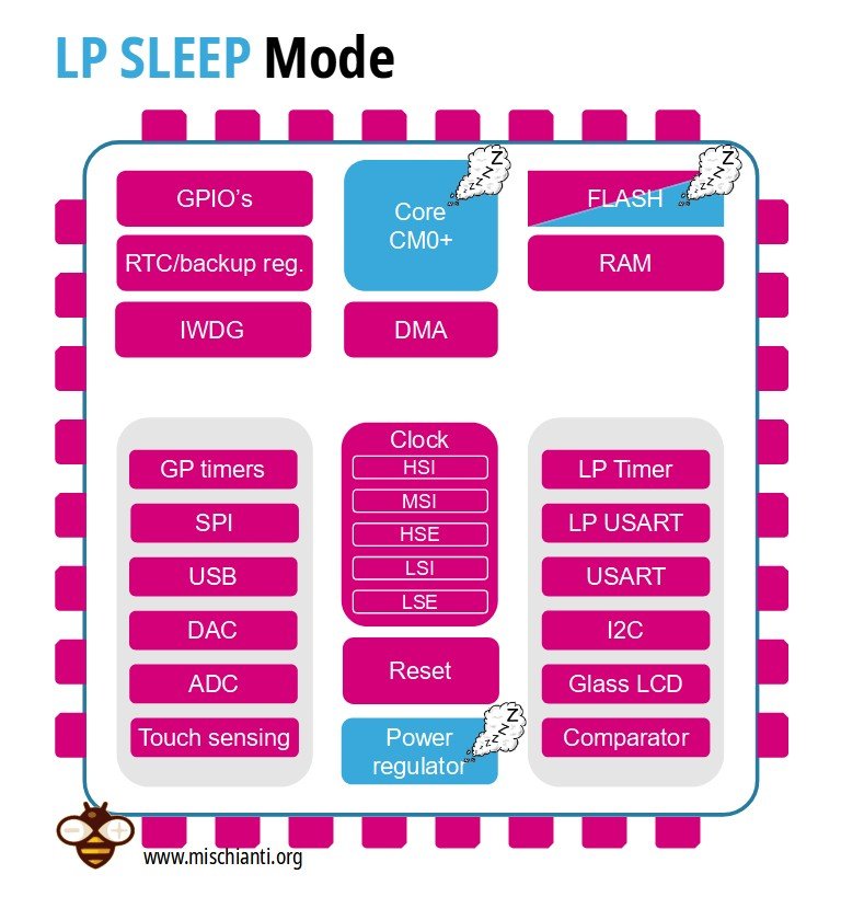
• Core is stopped
• Peripherals are running
• Power regulator is in Low Power mode
• FLASH can be in Power Down mode
• VREFINT can be OFF
Low-power sleep mode is essentially a combination of Low-power run mode and Sleep mode. Not only is the Cortex-M0+ core stopped, but the regulator is placed into low power mode, which means the same conditions as those from Low-power run mode must be met.
Low-Power Sleep mode is wrapped with Sleep mode in the STM32LowPower library.
Sleep mode in Arduino framework
In the Arduino framework, this state is renamed in sleep mode and the code
/**
  * @brief  Enable the sleep low power mode (STM32 sleep). Exit this mode on
  *         interrupt or in n milliseconds.
  * @param  ms: optional delay before leave the sleep mode (default: 0).
  * @retval None
  */
void STM32LowPower::sleep(uint32_t ms)
{
  if ((ms != 0) || _rtc_wakeup) {
    programRtcWakeUp(ms, SLEEP_MODE);
  }
  LowPower_sleep(PWR_LOWPOWERREGULATOR_ON);
}
is the same as idle, but with the low power regulator active.
Stop Mode
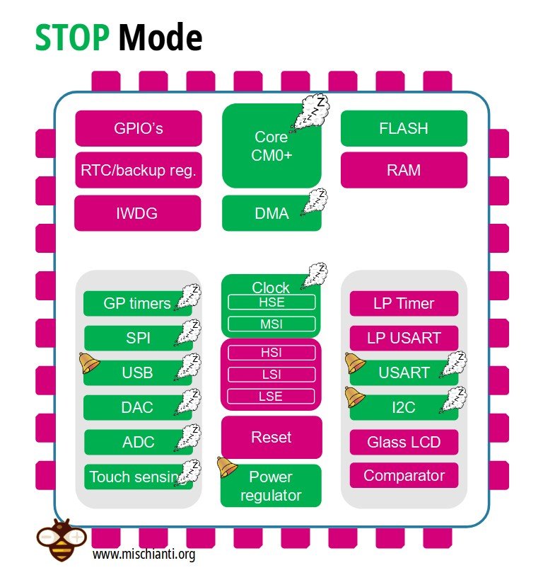
- Core is stopped
- HSE, MSI clocks are OFF
- SRAM and registers content is preserved
- Peripherals with HSI, LSI, LSE clock option can be ON
- GPIO’s keep their setup
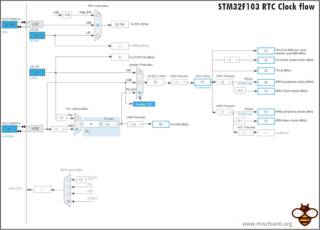
The real-time clock is powered by LSI (low speed internal) clock source in stop mode. HIS (High speed internal) and HSE (External) clock buses are turned off. The HSI can provide limited functionality to peripherals capable of running in Stop mode. The HSI will only feed the peripheral that requested it and will automatically be disabled when it is no longer needed. For example, the USART and I2C can still receive data in Stop mode by waking up the HSI when required.
Stop mode has the potential to achieve current consumption on the order of nanoamps while still retaining the SRAM and register contents.
Stop mode is wrapped with DeepSleep mode in the STM32LowPower library
The power regulator is in low power mode.
The regulator in low power mode means flash is also in power-down mode. In stop mode, all clocks are stopped except the one connected to RTC. Exiting from stop mode is possible with real-time clock interrupt or any other global interrupt.
Many of the power saving options may be ignored in order to achieve latency on par with that of Low-power run mode. Further complicating matters is the limited number of available wake-up sources.
DeepSleep in Arduino framework
The deep sleep uses the Stop modality and allows to set only an HardwareSerial as a wake-up source.
/**
  * @brief  Enable the deepsleep low power mode (STM32 stop). Exit this mode on
  *         interrupt or in n milliseconds.
  * @param  ms: optional delay before leave the deepSleep mode (default: 0).
  * @retval None
  */
void STM32LowPower::deepSleep(uint32_t ms)
{
  if ((ms != 0) || _rtc_wakeup) {
    programRtcWakeUp(ms, DEEP_SLEEP_MODE);
  }
  LowPower_stop(_serial);
}
Standby Mode

- Core and all peripherals are OFF, except RTC and IWDG if enabled
- HSE, MSI, HSI clocks are OFF, LSI LSE can be ON
- SRAM and registers content is lost, except RTC, and standby circuitry
- GPIO’s are in high Z, except Reset, RTC OUT and WKUP 1,2,3
Unlike Stop mode, entering Standby mode is relatively simple because users have fewer options. The only oscillators available are the LSI and LSE. The only peripherals that can function are the RTC and IWDG. The voltage regulator is entirely disabled, and all I/O pins are set as high impedance (so saving the context is pointless).
There are also fewer options for exiting Standby mode. Only a rising edge on the wake-up pin, one of the RTC wake-up events, or a reset will wake the device.
Standby mode is wrapped with Shutdown mode in the STM32LowPower library
The biggest problem with Standby mode is that it does not preserve the contents of SRAM or the registers (except the RTC registers, RTC backup registers, and the Standby circuitry). After waking from Standby mode, the program execution restarts in the same way as if a reset had occurred.
Just how long depends on how much current is consumed during the wake-up/reinitialization process. Standby mode has the longest wake-up time. So It makes sense only if the device will have to be in Standby mode for a very long period.
Shutdown in Arduino framework
Also, for shutdown, we are going to wrap a native Power Saving mode, in this case, the mode is Standy.
/**
  * @brief  Enable the shutdown mode.The board reset when leaves this mode.
  *         If shutdown mode not available, use standby mode instead.
  * @param  None
  * @retval None
  */
void LowPower_shutdown()
{
  __disable_irq();
#if defined(PWR_CR1_LPMS)
  /* LSE must be on to use shutdown mode */
  if (__HAL_RCC_GET_FLAG(RCC_FLAG_LSERDY) == SET) {
    HAL_PWREx_EnterSHUTDOWNMode();
  } else
#endif
  {
    LowPower_standby();
  }
}
Low-power mode brief comparison STM32L0, STM32F1 and STM32F4
Now we are going to start some tests, but I’d like to add this brief alert. The world of STM32 is vast, and there are a lot of differences from one micro to another, so in the test, we can find some un-comprehensive results.
I add a table that explains the primary difference between the main microcontroller type to understand better.
| MCU series | STM32L0/STM32F1 Series | STM32L4 Series |
|---|---|---|
| Sleep modes | Either main or low-power regulator, Flash memory clock off with low-power sleep | Low-power regulator on, main regulator configurable, Flash memory clock configurable |
| Stop modes | Single stop mode | Stop0, Stop1, and Stop2 steps |
| Standby | Available | Available and also special shutdown mode implemented. |
Behavior after wake-up
| Mode | After wake-up | Reason |
|---|---|---|
| Idle/Sleep mode | Continue to run down in the main program | Data storage registers such as flash and SRAM are still in power supply state |
| Deep Sleep | Continue to run down in the main program | Data storage registers such as flash and SRAM are still in power supply state |
| Shutdown | Run the main program from the beginning (reset) | All peripherals except the backup register and standby circuit stop running |
Thanks
- STM32F1 Blue-Pill: pinout, specs, and Arduino IDE configuration (STM32duino and STMicroelectronics)
- STM32: program (STM32F1) via USB with STM32duino bootloader
- STM32: programming (STM32F1 STM32F4) via USB with HID boot-loader
- STM32F4 Black-Pill: pinout, specs, and Arduino IDE configuration
- STM32: ethernet w5500 with plain HTTP and SSL (HTTPS)
- STM32: ethernet enc28j60 with plain HTTP and SSL (HTTPS)
- STM32: WiFiNINA with ESP32 WiFi Co-Processor
- How to use SD card with stm32 and SdFat library
- \STM32: SPI flash memory FAT FS
- STM32: internal RTC, clock, and battery backup (VBAT)
- STM32 LoRa
- STM32 Power saving
- STM32F1 Blue-Pill clock and frequency management
- STM32F4 Black-Pill clock and frequency management
- Intro and Arduino vs STM framework
- Library LowPower, wiring, and Idle (STM Sleep) mode
- Sleep, deep sleep, shutdown, and power consumption
- Wake up from RTC alarm and Serial
- Wake up from the external source
- Backup domain intro and variable preservation across reset
- RTC backup register and SRAM preservation
- STM32 send emails with attachments and SSL (like Gmail): w5500, enc28j60, SD, and SPI Fash
- FTP server on STM32 with w5500, enc28j60, SD Card, and SPI Flash