Ebyte LoRa E32 & MicroPython: exploring library – 2
The Ebyte LoRa E32 library is a comprehensive tool designed to facilitate seamless communication with LoRa wireless modules. Developed for programmers and tech enthusiasts alike, the library enables a smooth interfacing with Ebyte’s LoRa E32 devices using MicroPython, a lean and efficient implementation of the Python 3 programming language.
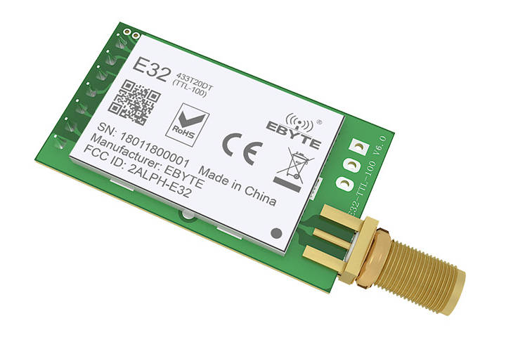
Here my device selection AliExpress (433MHz 5Km) - AliExpress (433MHz 8Km) - AliExpress (433MHz 16Km) - AliExpress (868MHz 915MHz 5.5Km) - AliExpress (868MHz 915MHz 8Km)
They can work over a distance of 3000m to 8000m and have many features and parameters.
So I created this library to simplify the usage.
Library
To install the library, you can download It from this GitHub repository:
Or you can install it via Pypi with the command:
pip install ebyte-lora-e32
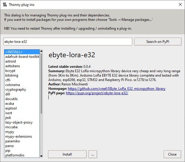
On Thonny IDE, you can use Tools --> Manage plug-ins... .
Pinout
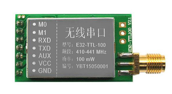
| Pin No. | Pin item | Pin direction | Pin application |
|---|---|---|---|
| 1 | M0 | Input(weak pull-up) | Work with M1 & decide on the four operating modes. Floating is not allowed, it can be ground. |
| 2 | M1 | Input(weak pull-up) | Work with M1 & decide on the four operating modes. Floating is not allowed. It can be ground. |
| 3 | RXD | Input | TTL UART inputs connect to external (MCU, PC) TXD output pin. It can be configured as open-drain or pull-up input. |
| 4 | TXD | Output | Work with M0 & decide on the four operating modes. Floating is not allowed. It can be ground. |
5 | AUX | Output | TTL UART outputs connect to external RXD (MCU, PC) input pin. It can be configured as open-drain or push-pull output. |
| 6 | VCC | Power supply 2.3V~5.5V DC | |
| 7 | GND | Ground |
As you can see, you can set various modes via M0 and M1 pins.
| Mode | M1 | M0 | Explanation |
|---|---|---|---|
| Normal | 0 | 0 | UART and the wireless channel are good to go |
| Wake-Up | 0 | 1 | Used in setting parameters. Transmitting and receiving are disabled. |
| Power-Saving | 1 | 0 | Same as normal, but a preamble code is added to transmitted data for waking-up the receiver. |
| Sleep | 1 | 1 | Used in setting parameters. Transmitting and receiving disabled. |
For the next simple test, we are going to use Normal mode.
Some pins can be used statically, but If you connect Them to the microcontroller and configure them in the library, you gain in performance, and you can control all modes via software, but we will explain better next.
Fully connected schema
As I already said, It’s not essential to connect all pins to the output of the microcontroller, you can put M0 and M1 pins to HIGH or LOW to get the desired configuration, and if you don’t connect AUX, the library sets a reasonable delay to be sure that the operation is complete.
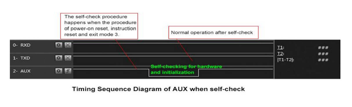
AUX pin
When transmitting, data can be used to wake up external MCU and return HIGH on data transfer finish.
When receiving, AUX goes LOW and returns HIGH when the buffer is empty.
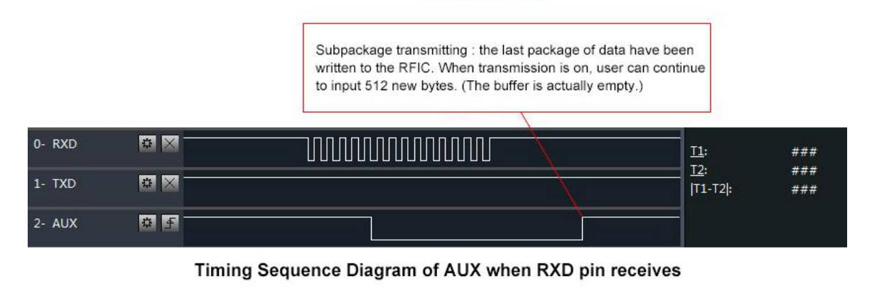
It’s also used for self-checking to restore regular operation (on power-on and sleep/program mode).
Wiring
esp32
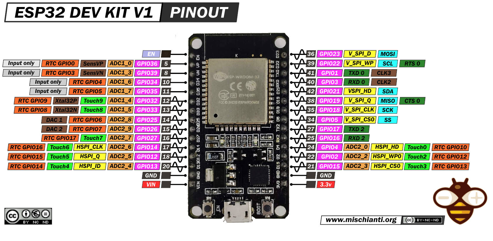
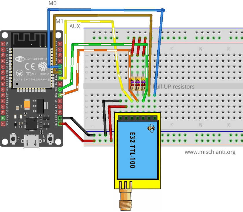
| M0 | D21 |
| M1 | D19 |
| TX | PIN RX2 (PullUP 4,7KΩ) |
| RX | PIN TX3 (PullUP 4,7KΩ) |
| AUX | PIN D18 (PullUP 4,7KΩ) (D15 to wake up) |
| VCC | 5V |
| GND | GND |
uart2 = UART(2)
lora = LoRaE32('433T20D', uart2, aux_pin=15, m0_pin=21, m1_pin=19)
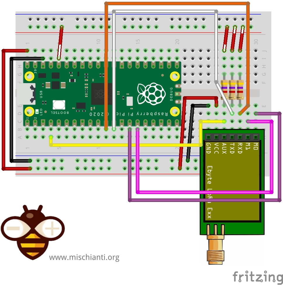
Raspberry Pi Pico
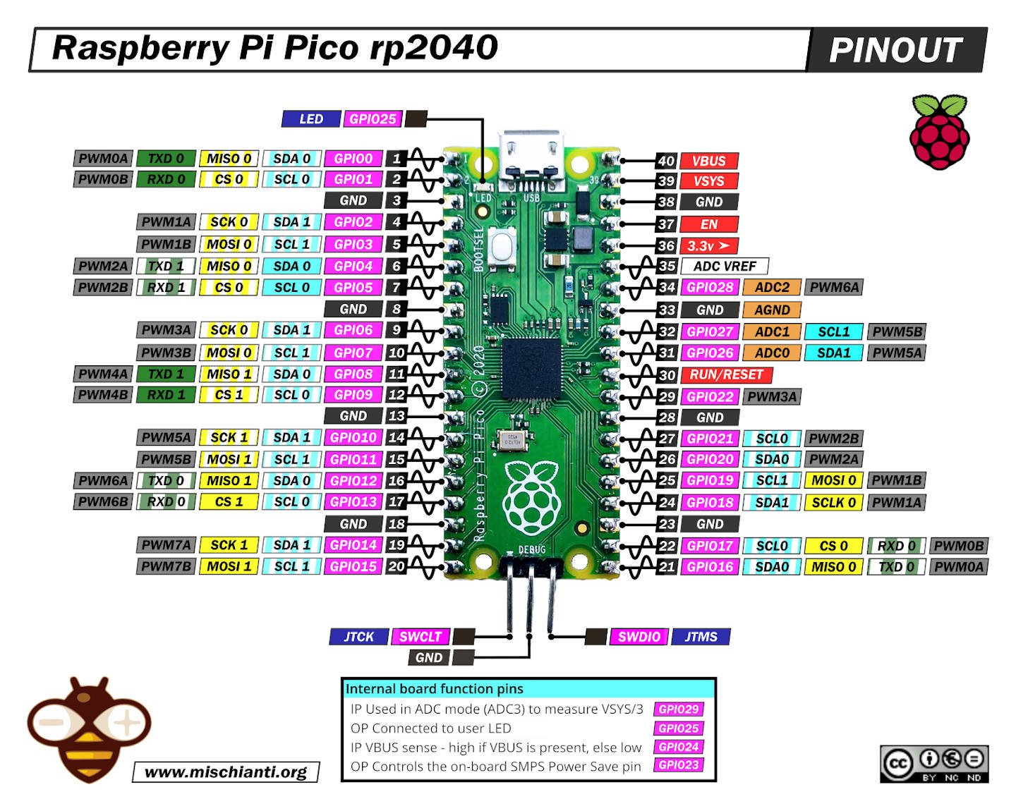
And here is the connection diagram. For this test, you can remove the AUX pin connection. You can also see that I use a different default Serial port because It differs from the Arduino environment.
MicroPython default setting

| E32 | Raspberry Pi Pico |
|---|---|
| M0 | 10 |
| M1 | 11 |
| RX | TX1 GPIO4 (PullUP 4,7KΩ) |
| TX | RX1 GPIO5 (PullUP 4,7KΩ) |
| AUX | 2 (PullUP 4,7KΩ) |
| VCC | 5v |
| GND | GND |
Pay attention UART(1) use different pin in MicroPython than Arduino environment Serial1
# Create a UART object to communicate with the LoRa module with Raspberry Pi Pico
uart2 = UART(1)
lora = LoRaE32('433T20D', uart2, aux_pin=2, m0_pin=10, m1_pin=11)
Arduino default Serial
Arduino default Serial is different from MicroPython. Here is a schema to use the same interface.
| E32 | Raspberry Pi Pico |
|---|---|
| M0 | 10 |
| M1 | 11 |
| RX | TX1 GPIO8 (PullUP 4,7KΩ) |
| TX | RX1 GPIO9 (PullUP 4,7KΩ) |
| AUX | 2 (PullUP 4,7KΩ) |
| VCC | 5v |
| GND | GND |
For the Arduino standard pinout, you must change the UART declaration so uart2 = UART(1, rx=Pin(9), tx=Pin(8))
Constructor
I made a set of numerous constructors because we can have more options and situations to manage.
# Create a UART object to communicate with the LoRa module with ESP32
# uart2 = UART(2)
# Create a LoRaE32 object, passing the UART object and pin configurations
# lora = LoRaE32('433T20D', uart2, aux_pin=15, m0_pin=21, m1_pin=19)

# Create a UART object to communicate with the LoRa module with Raspberry Pi Pico
#uart2 = UART(1)
# Use the Serial1 pins of Arduino env on the Raspberry Pi Pico
uart2 = UART(1, rx=Pin(9), tx=Pin(8))

lora = LoRaE32('433T20D', uart2, aux_pin=2, m0_pin=10, m1_pin=11)
The provided code segment demonstrates how to set up a UART (Universal Asynchronous Receiver/Transmitter) connection with a LoRa module, specifically an Ebyte LoRa E32 device, using either the ESP32 or Raspberry Pi Pico microcontrollers. UART is a hardware device or a protocol that helps in serial communication between two devices.
Initially, the code sets up the UART interface, which is used for serial communication between the microcontroller (either ESP32 or Raspberry Pi Pico) and the LoRa module.
In the case of ESP32, the UART object would be initialized as uart2 = UART(2). This line is commented out in the given code because the setup is demonstrated for the Raspberry Pi Pico.
For the Raspberry Pi Pico, there are two alternatives presented. The first one is a simple initialization: uart2 = UART(1). The second one specifies the particular pins for RX (receiving data) and TX (transmitting data): uart2 = UART(1, rx=Pin(9), tx=Pin(8)). This line sets the UART channel to 1 and specifies that Pin 9 is for receiving data (rx) and Pin 8 is for transmitting data (tx).
The next step is to create an instance of the LoRaE32 class. The LoRaE32() constructor is used to initialize the object named lora. It takes four parameters:
- The model name of the Ebyte LoRa E32 module, in this case, ‘433T20D’.
- The UART object (
uart2), which enables serial communication with the LoRa module. - The AUX pin number, which is used for auxiliary functions like indicating the operational status of the module or for handshaking. Here, it’s set to 2 for Raspberry Pi Pico.
- The M0 and M1 pin numbers, which are used to switch the module between different operating modes. In this case, they are set to 10 and 11, respectively, for the Raspberry Pi Pico.
By initializing the lora object with these parameters, the microcontroller is ready to interact with the LoRa module, and you can start configuring and using the module for wireless communication.
Remember to uncomment or modify the code according to the microcontroller you are using, whether it’s ESP32 or Raspberry Pi Pico.
begin()
The begin command is used to startup Serial and pins in input and output mode.
code = lora.begin()
print(ResponseStatusCode.get_description(code))
The provided lines of code are used to start the LoRa module and print a description of the response status code obtained during the initialization process.
code = lora.begin(): This line of code calls thebegin()function on theloraobject, which was previously instantiated as an instance of theLoRaE32class. Thebegin()function is typically used to initialize the LoRa module and prepare it for communication. This function might include steps like setting the LoRa module to the correct mode, checking that it is responding correctly, or even performing some initial configuration. The function returns a status code that indicates whether the initialization process was successful or if any errors occurred.print(ResponseStatusCode.get_description(code)): This line is used to print a human-readable description of the response status code that was returned by thebegin()function. Theget_description()function is a method of theResponseStatusCodeclass, which is designed to map status code values to their corresponding descriptions. By passing thecodereturned bybegin()toget_description(), you can get a text description of the initialization result, which can be very helpful for debugging. For example, if the initialization was successful, you might get a description like “Success”, while if an error occurred, you might get a message indicating the type of error.
Configuration and information method
There are many methods for managing configuration and getting information about the device.
getConfiguration
In the context of a LoRa E32 module, maintaining a keen awareness of its current configuration can be crucial in managing its operations effectively. In this regard, the ability to retrieve and understand the module’s configuration is fundamental. The Python code provided above demonstrates a straightforward method to achieve this task using the lora_e32 and lora_e32_operation_constant libraries.
from lora_e32 import LoRaE32, print_configuration, Configuration
from lora_e32_operation_constant import ResponseStatusCode

code, configuration = lora.get_configuration()

print(ResponseStatusCode.get_description(code))
print_configuration(configuration)
The LoRaE32 class, which is central to interacting with the LoRa module, and the print_configuration function, which translates the configuration data into a human-readable format. It also imports the Configuration class that represents the module’s configuration and the ResponseStatusCode class to interpret the response of the get_configuration() function.
----------------------------------------
HEAD : 0b11000000 192

AddH : 0
AddL : 2
Chan : 23  ->  433

SpeedParityBit    : 0b0  ->  8N1 (Default)
SpeedUARTDatte : 0b11  ->  9600bps (default)
SpeedAirDataRate  : 0b10  ->  2.4kbps (default)
OptionTrans       : 0b1  ->  Fixed transmission (first three bytes can be used a
s high/low address and channel)
OptionPullup      : 0b1  ->  TXD, RXD, AUX are push-pulls/pull-ups (default)
OptionWakeup      : 0b0  ->  250ms (default)
OptionFEC         : 0b1  ->  Turn on Forward Error Correction Switch (Default)
OptionPower       : 0b0  ->  20dBm (Default)
----------------------------------------
The final part of the code prints the configuration using the print_configuration() function. This function provides a structured overview of the current LoRa module’s settings, offering a snapshot of its operational parameters. These parameters include various details, such as the header of the configuration message, the device address, the operating channel, the speed settings, and the transmission settings, including the mode, I/O mode, wireless wake-up time, error correction, and transmission power. Understanding these parameters is pivotal in diagnosing operational issues, fine-tuning performance, and ensuring successful data transmission over the LoRa network.
setConfiguration
Configuring the LoRa E32 module to meet specific operational requirements is an essential aspect of using it effectively. This Python code illustrates how to define and set the configuration of a LoRa module, offering a clear demonstration of the flexibility and control provided by the lora_e32 library.
configuration_to_set = Configuration('433T20D')
configuration_to_set.ADDL = 0x02
configuration_to_set.OPTION.fixedTransmission = FixedTransmission.FIXED_TRANSMISSION

code, confSetted = lora.set_configuration(configuration_to_set)
The process begins with the creation of a Configuration object. This object represents the entire configuration of the LoRa module. The user sets the parameters of the configuration according to their specific needs. In this example, the configuration is tailored to the ‘433T20D’ model of the LoRa module, and the lower part of the address (ADDL) is set to 0x02. The fixed transmission mode is also set using a constant from the FixedTransmission class.
Once the configuration object has been suitably defined, it’s passed to the set_configuration() function of the LoRaE32 object. This function uploads the defined configuration to the LoRa module, effectively changing its operation according to the new settings.
class Configuration:
class Speed:
    def __init__(self, model):
        self.model = model

        self.airDataRate = AirDataRate.AIR_DATA_RATE_010_24
        self.uartBaudRate = UARTBaudRate.BPS_9600
        self.uartParity = UARTParity.MODE_00_8N1


class Option:
    def __init__(self, model):
        self.model = model

        self.transmissionPower = TransmissionPower(self.model).get_transmission_power().get_default_value()
        self.fec = ForwardErrorCorrectionSwitch.FEC_1_ON
        self.wirelessWakeupTime = WirelessWakeUpTime.WAKE_UP_250
        self.ioDriveMode = IODriveMode.PUSH_PULLS_PULL_UPS
        self.fixedTransmission = FixedTransmission.TRANSPARENT_TRANSMISSION


class Configuration:
    def __init__(self, model):
        self.HEAD = 0
        self.ADDH = 0
        self.ADDL = 0
        self.SPED = Speed(model)
        self.CHAN = 23
        self.OPTION = Option(model)
The code also gives a glimpse into the structure of the Configuration class, showcasing its nested classes Speed and Option. These classes encapsulate different aspects of the LoRa module’s configuration, such as the speed of data transmission and various operating options. It’s worth noting that the classes contain a multitude of parameters, each with predefined constants for easier and more reliable configuration. These parameters include air data rate, UART baud rate, UART parity, transmission power, forward error correction switch, wireless wake-up time, I/O drive mode, and fixed transmission.
The nested structure of the Configuration class and the use of predefined constants underscore the organized and intuitive approach of the lora_e32 library in managing the LoRa module’s configuration. This modular design allows developers to tailor the LoRa module’s operation to their specific needs, enabling more efficient and effective use of the technology.
Basic configuration option
| ADDH | High address byte of the module (the default 00H) | 00H-FFH |
| ADDL | Low address byte of the module (the default 00H) | 00H-FFH |
| SPED | Information about data rate parity bit and Air data rate | |
| CHAN | Communication channel(410M + CHAN*1M), default 17H (433MHz), valid only for 433MHz device check below to check the correct frequency of your device | 00H-1FH |
| OPTION | Type of transmission, pull-up settings, wake-up time, FEC, Transmission power |
SPED detail
UART Parity bit: UART mode can be different between communication parties
| 7 | 6 | UART parity bit | Constant value |
|---|---|---|---|
| 0 | 0 | 8N1 (default) | MODE_00_8N1 |
| 0 | 1 | 8O1 | MODE_01_8O1 |
| 1 | 0 | 8 E1 | MODE_10_8E1 |
| 1 | 1 | 8N1 (equal to 00) | MODE_11_8N1 |
UART baud rate: UART baud rate can be different between communication parties. The UART baud rate has nothing to do with wireless transmission parameters & won’t affect the wireless transmit/receive features.
| 5 | 4 | 3 | TTL UART baud rate(bps) | Constant value |
|---|---|---|---|---|
| 0 | 0 | 0 | 1200 | UART_BPS_1200 |
| 0 | 0 | 1 | 2400 | UART_BPS_2400 |
| 0 | 1 | 0 | 4800 | UART_BPS_4800 |
| 0 | 1 | 1 | 9600 (default) | UART_BPS_9600 |
| 1 | 0 | 0 | 19200 | UART_BPS_19200 |
| 1 | 0 | 1 | 38400 | UART_BPS_38400 |
| 1 | 1 | 0 | 57600 | UART_BPS_57600 |
| 1 | 1 | 1 | 115200 | UART_BPS_115200 |
Air data rate: The lower the air data rate, the longer the transmitting distance, better anti-interference performance, and longer transmitting time; the air data rate must be constant for both communication parties.
| 2 | 1 | 0 | Air data rate(bps) | Constant value |
|---|---|---|---|---|
| 0 | 0 | 0 | 0.3k | AIR_DATA_RATE_000_03 |
| 0 | 0 | 1 | 1.2k | AIR_DATA_RATE_001_12 |
| 0 | 1 | 0 | 2.4k (default) | AIR_DATA_RATE_010_24 |
| 0 | 1 | 1 | 4.8k | AIR_DATA_RATE_011_48 |
| 1 | 0 | 0 | 9.6k | AIR_DATA_RATE_100_96 |
| 1 | 0 | 1 | 19.2k | AIR_DATA_RATE_101_192 |
| 1 | 1 | 0 | 19.2k (same to 101) | AIR_DATA_RATE_110_192 |
| 1 | 1 | 1 | 19.2k (same to 101) | AIR_DATA_RATE_111_192 |
OPTION detail
Transmission mode: The first three bytes of each user’s data frame can be used as high/low address and channel in fixed transmission mode. The module changes its address and channel when transmitted. It will revert to the original setting after completing the process.
| 7 | Fixed transmission enabling bit(similar to MODBUS) | Constant value |
|---|---|---|
| 0 | Transparent transmission mode | FT_TRANSPARENT_TRANSMISSION |
| 1 | Fixed transmission mode | FT_FIXED_TRANSMISSION |
IO drive mode: this bit is used for the module’s internal pull-up resistor. It also increases the level of adaptability in case of an open drain. But in some cases, it may need an external pull-up resistor.
| 6 | IO drive mode ( default 1) | Constant value |
|---|---|---|
| 1 | TXD and AUX push-pull outputs, RXD pull-up inputs | IO_D_MODE_PUSH_PULLS_PULL_UPS |
| 0 | TXD、AUX open-collector outputs, RXD open-collector inputs | IO_D_MODE_OPEN_COLLECTOR |
Wireless wake-up time: the transmit & receive module work in mode 0, whose delay time is invalid & can be an arbitrary value; the transmitter works in mode one can send the preamble code of the corresponding time continuously when the receiver operates in mode 2, the time means the monitor interval time (wireless wake-up). Only the data from the transmitter that works in mode one can be
received.
| 5 | 4 | 3 | Wireless wake-up time | Constant value |
|---|---|---|---|---|
| 0 | 0 | 0 | 250ms (default) | WAKE_UP_250 |
| 0 | 0 | 1 | 500ms | WAKE_UP_500 |
| 0 | 1 | 0 | 750ms | WAKE_UP_750 |
| 0 | 1 | 1 | 1000ms | WAKE_UP_1000 |
| 1 | 0 | 0 | 1250ms | WAKE_UP_1250 |
| 1 | 0 | 1 | 1500ms | WAKE_UP_1500 |
| 1 | 1 | 0 | 1750ms | WAKE_UP_1750 |
| 1 | 1 | 1 | 2000ms | WAKE_UP_2000 |
FEC: after turning off FEC, the actual data transmission rate increases while the anti-interference ability decreases. Also, the transmission distance is relatively short, and both communication parties must keep on the same pages about turn-on or turn-off FEC.
| 2 | FEC switch | Constant value |
|---|---|---|
| 0 | Turn off FEC | FEC_0_OFF |
| 1 | Turn on FEC (default) | FEC_1_ON |
Transmission power
Exists difference from power devices, for example the 20dBm modules have:
| 1 | 0 | Transmission power (approximation) | Constant value |
|---|---|---|---|
| 0 | 0 | 20dBm (default) | POWER_20 |
| 0 | 1 | 17dBm | POWER_17 |
| 1 | 0 | 14dBm | POWER_14 |
| 1 | 1 | 10dBm | POWER_10 |
The 27dBm modules have:
| 1 | 0 | Transmission power (approximation) | Constant value |
|---|---|---|---|
| 0 | 0 | 27dBm (default) | POWER_27 |
| 0 | 1 | 24dBm | POWER_24 |
| 1 | 0 | 21dBm | POWER_21 |
| 1 | 1 | 18dBm | POWER_18 |
And the 30dBm modules:
| 1 | 0 | Transmission power (approximation) | Constant value |
|---|---|---|---|
| 0 | 0 | 30dBm (default) | POWER_30 |
| 0 | 1 | 27dBm | POWER_27 |
| 1 | 0 | 24dBm | POWER_24 |
| 1 | 1 | 21dBm | POWER_21 |
Also, the frequencies change with the model version.
| Model freq. | Start value to add Channel |
|---|---|
| 433 | 410 |
| 170 | 130 |
| 470 | 370 |
| 868 | 862 |
| 900 | 862 |
| 915 | 900 |
Send receive message
First, we must introduce a simple but useful method to check if something is in the receiving buffer.
if lora.available() > 0:
It’s simple to return how many bytes you have in the current stream.
Normal transmission mode
Normal/Transparent transmission mode sends messages to all devices with the same address and channel.
The first method is sendMessage and is used to send a String to a device in Normal mode.
message = 'Hello, world!'
code = lora.send_transparent_message(message)
print("Send message: {}", ResponseStatusCode.get_description(code))
The other device simply does on the loop.
while True:
    if lora.available() > 0:
        code, value = lora.receive_message()
        print(ResponseStatusCode.get_description(code))

        print(value)
        utime.sleep_ms(2000)
Pay attention if you receive multiple messages in the buffer, and you don’t want reading all in one time you must use a delimiter parameter
Use dictionary
There is an alternative method that allows sending a dictionary.
lora.send_transparent_dict({'pippo': 'fixed', 'pippo2': 'fixed2'})
And the respective receiver method.
code, value = lora.receive_dict()
Fixed mode instead of normal mode
In some manner, I create a set of methods to use with fixed transmission
Fixed transmission
You need to change only the sending method because the destination device doesn’t receive the preamble with Address and Channel when setting the fixed mode.
Fixed transmission has more scenarios
If you send it to a specific device (second scenario Fixed transmission), you must add ADDL, ADDH, and CHAN to identify It directly.
code = lora.send_fixed_message(0, 0x01, 23, message)
If you want to send a message to all devices in a specified Channel, you can use this method.
code = lora.send_broadcast_message(23, message)
If you wish to receive all broadcast messages in the network, you must set your ADDH and ADDL with BROADCAST_ADDRESS.
# Set the configuration to default values and print the updated configuration to the console
# Not needed if already configured
configuration_to_set = Configuration('433T20D')
# With BROADCASS ADDRESS we receive all message
configuration_to_set.ADDL = BROADCAST_ADDRESS
configuration_to_set.ADDH = BROADCAST_ADDRESS
configuration_to_set.OPTION.fixedTransmission = FixedTransmission.FIXED_TRANSMISSION
code, confSetted = lora.set_configuration(configuration_to_set)
print("Set configuration: {}", ResponseStatusCode.get_description(code))
Thanks
Now you have all the information to do your work, but I think It’s important to show some real examples to understand better all the possibilities.
- EByte LoRa E32 & MicroPython: specifications, overview and first use
- EByte LoRa E32 & MicroPython: exploring MicroPython library
- EByte LoRa E32 & MicroPython: detailed look at the configuration
- EByte LoRa E32 & MicroPython: a deep dive into transmission types