EByte LoRa E32 & MicroPython: a detailed look at configuration – 3
In the world of Internet of Things (IoT) and wireless communication, long-range and low-power transmission technologies are critical to connecting devices over significant distances. LoRa (Long Range) technology is one such innovation, and Ebyte’s LoRa E32 series modules are renowned for their ease of use and versatility in various applications. This article titled “Ebyte LoRa E32 & MicroPython: Configuration” dives into the practical aspects of interfacing and configuring the Ebyte LoRa E32 modules using MicroPython, a lean and efficient Python variant for microcontrollers.

We begin by exploring the basics of the LoRa technology and the E32 module’s specifications. Following this, we delve into the core of the article – setting up the environment, establishing a connection, and guiding you through the process of configuring the Ebyte LoRa E32 module using MicroPython. We walk you through each step, from installation and initialization to detailed configuration settings, ensuring that you can maximize the capabilities of your LoRa E32 module. Whether you’re a hobbyist, a professional developer, or simply curious about wireless communication, this comprehensive guide will equip you with the knowledge to harness the power of LoRa technology in your projects.
My LoRa devices AliExpress (433MHz 5Km) - AliExpress (433MHz 8Km) - AliExpress (433MHz 16Km) - AliExpress (868MHz 915MHz 5.5Km) - AliExpress (868MHz 915MHz 8Km)
As I already specified, I created a dedicated library for this device because configuration and transmission mode are not so simple to manage.
Library
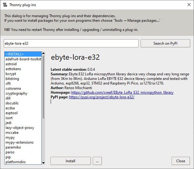
To install the library, you can download It from this GitHub repository:
Or you can install it via Pypi with the command:
pip install ebyte-lora-e32
On Thonny IDE, you can use Tools --> Manage plug-ins... .
Pinout
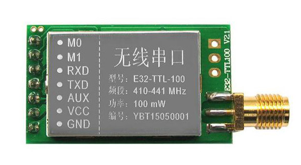
| Pin No. | Pin item | Pin direction | Pin application |
|---|---|---|---|
| 1 | M0 | Input(weak pull-up) | Work with M1 & decide on the four operating modes. Floating is not allowed, it can be ground. |
| 2 | M1 | Input(weak pull-up) | Work with M1 & decide on the four operating modes. Floating is not allowed. It can be ground. |
| 3 | RXD | Input | TTL UART inputs connect to external (MCU, PC) TXD output pin. It can be configured as open-drain or pull-up input. |
| 4 | TXD | Output | Work with M0 & decide on the four operating modes. Floating is not allowed. It can be ground. |
5 | AUX | Output | TTL UART outputs connect to external RXD (MCU, PC) input pin. It can be configured as open-drain or push-pull output. |
| 6 | VCC | Power supply 2.3V~5.5V DC | |
| 7 | GND | Ground |
As you can see, you can set various modes via M0 and M1 pins.
| Mode | M1 | M0 | Explanation |
|---|---|---|---|
| Normal | 0 | 0 | UART and the wireless channel are good to go |
| Wake-Up | 0 | 1 | Used in setting parameters. Transmitting and receiving are disabled. |
| Power-Saving | 1 | 0 | Same as normal, but a preamble code is added to transmitted data for waking-up the receiver. |
| Sleep | 1 | 1 | Used in setting parameters. Transmitting and receiving disabled. |
For the next simple test, we are going to use Normal mode.
Some pins can be used statically, but If you connect Them to the microcontroller and configure them in the library, you gain in performance, and you can control all modes via software, but we will explain better next.
Connection schemas for programming
For basic usage, we used this configuration. Still, you are working only in “Normal mode” in this configuration, and we will manage only the needed pin dynamic (RX, TX) to simplify the process.
Normal configuration (transparent)
esp32
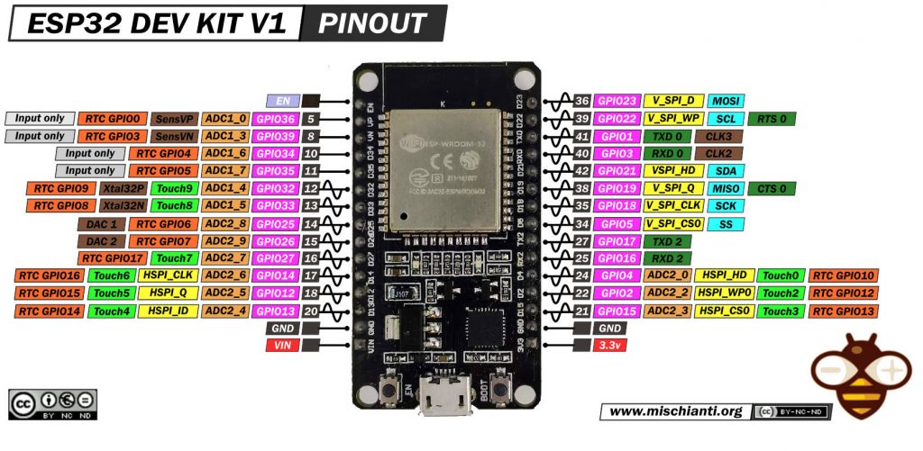
Here my selection of esp32 ESP32 Dev Kit v1 - TTGO T-Display 1.14 ESP32 - NodeMCU V3 V2 ESP8266 Lolin32 - NodeMCU ESP-32S - WeMos Lolin32 - WeMos Lolin32 mini - ESP32-CAM programmer - ESP32-CAM bundle - ESP32-WROOM-32 - ESP32-S
The wiring diagram is quite simple, and for now, I put M0 and M1 directly to GND for the test.
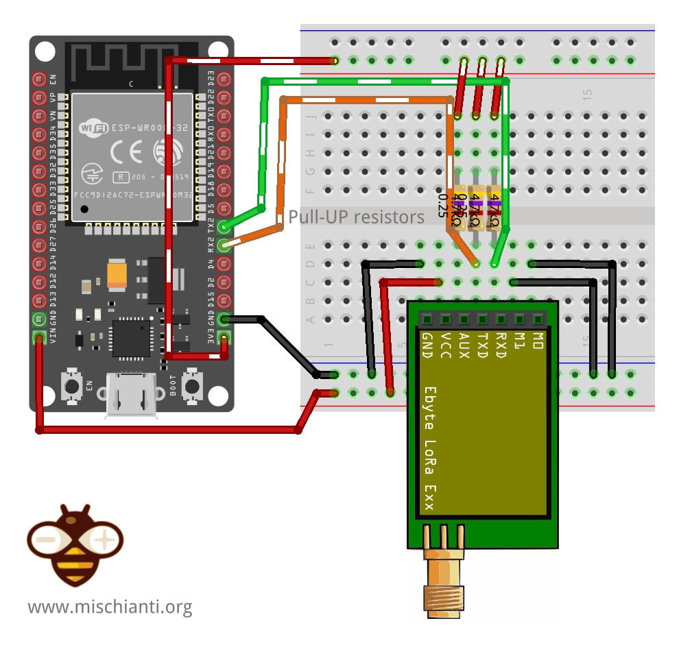
| E32 | esp32 |
|---|---|
| M0 | GND (Set normal mode) |
| M1 | GND (Set normal mode) |
| RX | TX2 (PullUP 4,7KΩ) |
| TX | RX2 (PullUP 4,7KΩ) |
| AUX | Not connected (better if you set a pin, but not needed for this test) |
| VCC | 5v |
| GND | GND |
Raspberry Pi Pico
And here is the connection diagram, for this test, you can remove the AUX pin connection. You can also see that I use a different default Serial port because It differs from the Arduino environment.
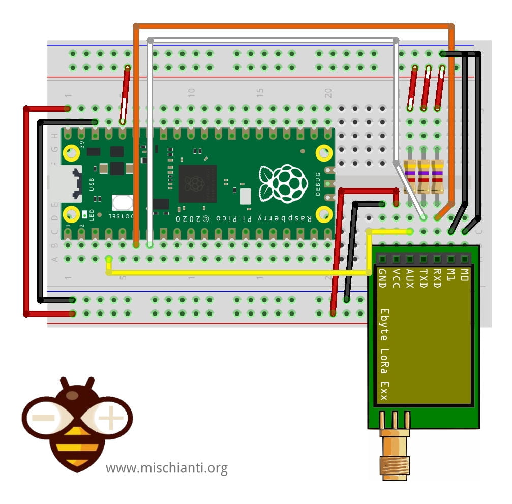
Pay attention UART(1) use different pin in MicroPython than Arduino environment Serial1
| E32 | esp32 |
|---|---|
| M0 | GND (Set normal mode) |
| M1 | GND (Set normal mode) |
| RX | TX1 GPIO4 (PullUP 4,7KΩ) |
| TX | RX1 GPIO5 (PullUP 4,7KΩ) |
| AUX | 2 (better if you set a pin, but not needed for this test) |
| VCC | 5v |
| GND | GND |
For the Arduino standard pinout, you must change the UART declaration so uart2 = UART(1, rx=Pin(9), tx=Pin(8))
Wiring for programming/sleep mode
To configure It, you must set M0 and M1 to high (remember to use 3.3v).
esp32
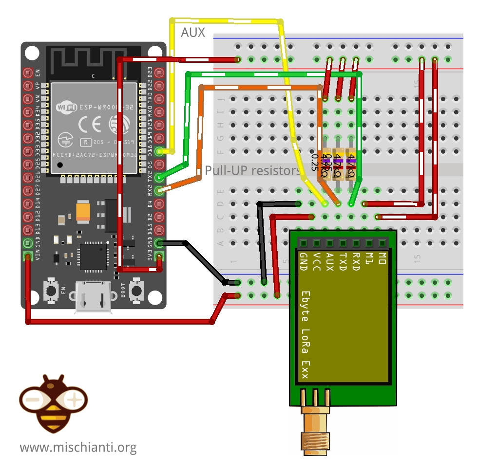
| E32 | esp32 |
|---|---|
| M0 | 3.3v (Set programming/sleep mode) |
| M1 | 3.3v (Set programming/sleep mode) |
| RX | TX2 (PullUP 4,7KΩ) |
| TX | RX2 (PullUP 4,7KΩ) |
| AUX | Not connected (better if you set a pin, but not needed for this test) |
| VCC | 5v |
| GND | GND |
In this mode, you can manage the configuration of the device
Raspberry Pi Pico
And here is the connection diagram, for this test, you can remove the AUX pin connection. You can also see that I use a different default Serial port because It differs from the Arduino environment.
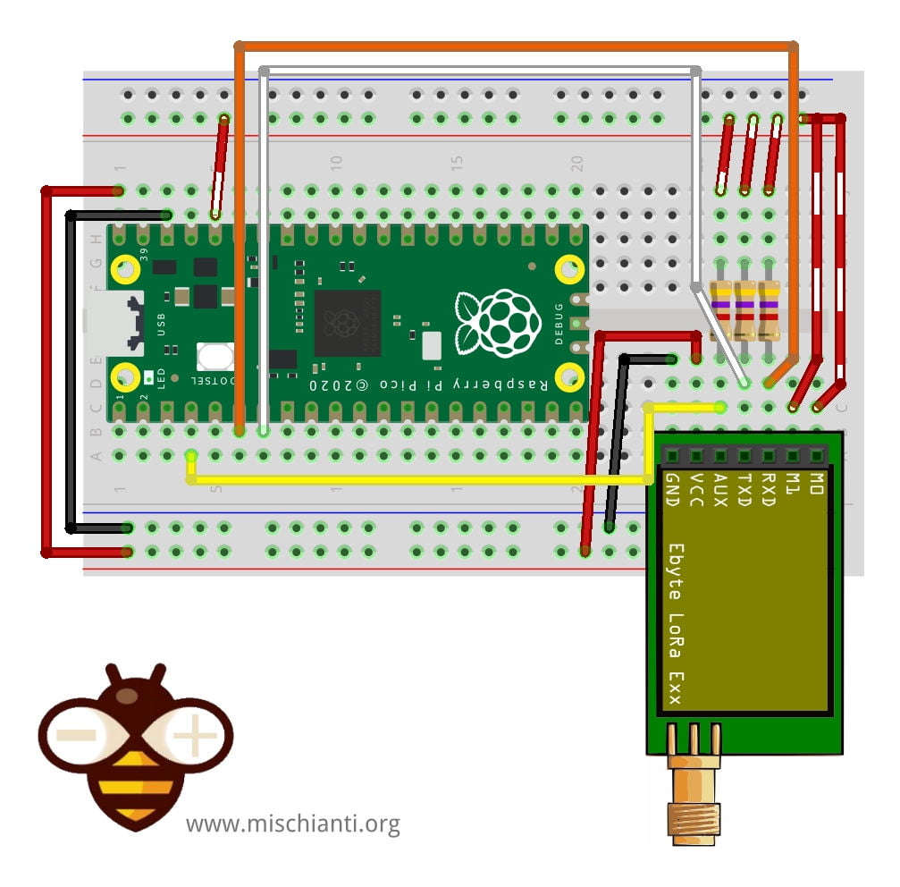
Pay attention UART(1) use different pin in MicroPython than Arduino environment Serial1
| E32 | esp32 |
|---|---|
| M0 | 3.3v (Set programming/sleep mode) |
| M1 | 3.3v (Set programming/sleep mode) |
| RX | TX1 GPIO4 (PullUP 4,7KΩ) |
| TX | RX1 GPIO5 (PullUP 4,7KΩ) |
| AUX | 2 (better if you set a pin, but not needed for this test) |
| VCC | 5v |
| GND | GND |
For the Arduino standard pinout, you must change the UART declaration so uart2 = UART(1, rx=Pin(9), tx=Pin(8))
Basic configuration option
| ADDH | High address byte of the module (the default 00H) | 00H-FFH |
| ADDL | Low address byte of the module (the default 00H) | 00H-FFH |
| SPED | Information about data rate parity bit and Air data rate | |
| CHAN | Communication channel(410M + CHAN*1M), default 17H (433MHz), valid only for 433MHz device | 00H-1FH |
| OPTION | Type of transmission, pull-up settings, wake-up time, FEC, Transmission power |
You can find configuration options in the Library article.
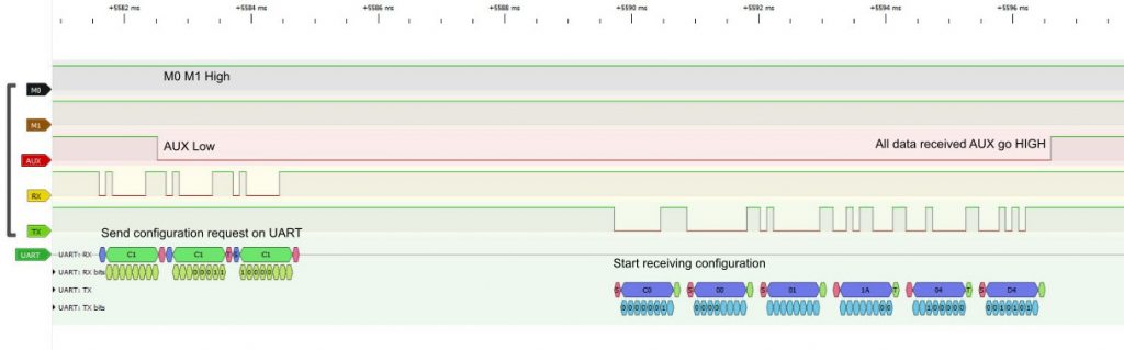
Get configuration
Arduino example sketch
# Author: Renzo Mischianti
# Website: www.mischianti.org
#
# Description:
# This script initializes the E32 LoRa module with MicroPython, retrieves the current configuration, and prints it to the console.
# The code demonstrates how to use the LoRaE32 library to interact with the module and read its configuration.
#
# Note: This code was written and tested using MicroPython on an ESP32 board.
#       It works with other boards, but you may need to change the UART pins.


from lora_e32 import LoRaE32, print_configuration, Configuration
from lora_e32_operation_constant import ResponseStatusCode
from machine import UART

uart2 = UART(2)

lora = LoRaE32('433T20D', uart2, aux_pin=15, m0_pin=21, m1_pin=19)

code = lora.begin()
print("Initialization: {}", ResponseStatusCode.get_description(code))

code, configuration = lora.get_configuration()

print("Retrieve configuration: {}", ResponseStatusCode.get_description(code))

print_configuration(configuration)
Here is the result of the sketch
----------------------------------------
HEAD : 0b11000000 192

AddH : 0
AddL : 2
Chan : 23  ->  433

SpeedParityBit    : 0b0  ->  8N1 (Default)
SpeedUARTDatte : 0b11  ->  9600bps (default)
SpeedAirDataRate  : 0b10  ->  2.4kbps (default)
OptionTrans       : 0b1  ->  Fixed transmission (first three bytes can be used a
s high/low address and channel)
OptionPullup      : 0b1  ->  TXD, RXD, AUX are push-pulls/pull-ups (default)
OptionWakeup      : 0b0  ->  250ms (default)
OptionFEC         : 0b1  ->  Turn on Forward Error Correction Switch (Default)
OptionPower       : 0b0  ->  20dBm (Default)
----------------------------------------
The process begins by importing the required classes and functions from the lora_e32 and lora_e32_operation_constant modules. The LoRaE32 class represents the LoRa module, the print_configuration function is used to print the configuration details in a readable format, and the Configuration class represents the module’s configuration. The ResponseStatusCode class is used to interpret the status code returned by the get_configuration() function.
The line code, configuration = lora.get_configuration() calls the get_configuration() function on the lora object (which represents the LoRa module) to retrieve the current configuration of the module. The function returns two values: a status code (code), which indicates whether the operation was successful and the current configuration (configuration).
The status code is printed in a human-readable format using the ResponseStatusCode.get_description(code) function, which takes the status code as an argument and returns a corresponding description. This provides feedback on whether the get_configuration() operation was successful.
The print_configuration(configuration) function is then used to print the retrieved configuration in a readable format. This function takes the configuration object as an argument and prints its attributes.
The configuration includes various parameters that determine the operation of the LoRa module:
HEAD: This is the header of the configuration message. Its value is fixed at 192 (0b11000000in binary form).AddHandAddL: These are the high and low parts of the device address, respectively. In this case, the address is 0.2.Chan: This is the channel number, which is mapped to a frequency. In this case, channel 23 corresponds to a frequency of 433 MHz.
The configuration also includes parameters for the speed settings:
SpeedParityBit: This sets the UART parity bit. The default (0b0) corresponds to 8N1, which means 8 data bits, no parity bit, and 1 stop bit.SpeedUARTDatte: This sets the UART baud rate. The default (0b11) corresponds to 9600 bps (bits per second).SpeedAirDataRate: This sets the air data rate. The default (0b10) corresponds to 2.4 kbps (kilobits per second).
The configuration further includes options for transmission settings:
OptionTrans: This determines the transmission mode. A value of0b1indicates fixed transmission mode, where the first three bytes of the message are used as the high and low address and the channel.OptionPullup: This sets the I/O mode for the TXD, RXD, and AUX pins. The default (0b1) indicates push-pull/pull-up mode.OptionWakeup: This sets the wireless wake-up time. The default (0b0) corresponds to 250 ms.OptionFEC: This enables or disables Forward Error Correction. The default (0b1) turns on FEC.OptionPower: This sets the transmission power. The default (0b0) corresponds to 20 dBm.
By calling get_configuration() and printing the result, you can check the current settings of your LoRa module and verify that it’s configured as expected.
Set configuration
Naturally, when you have a configuration you want to change for your purpose, I think you can get the configuration from a device, modify what you want and set It.
To the set_configuration you can pass an additional parameter permanentConfiguration, that allows you to lose the configuration at power down if you set False.
def set_configuration(self, configuration, permanentConfiguration=True) -> (ResponseStatusCode, Configuration):
Here is the sketch:
# Author: Renzo Mischianti
# Website: www.mischianti.org
#
# Description:
# This script demonstrates how to use the E32 LoRa module with MicroPython.
# It initializes the module, retrieves the current configuration,
# sets a new configuration, and restores the default configuration.
# It also includes examples of sending and receiving data using the module.
#
# Note: This code was written and tested using MicroPython on a ESP32 board.
#       It works with other boards, but you may need to change the UART pins.

from lora_e32 import LoRaE32, print_configuration, Configuration
from lora_e32_constants import OperatingFrequency, FixedTransmission, WirelessWakeUpTime, TransmissionPower, \
    TransmissionPower20, AirDataRate, UARTParity, UARTBaudRate
from lora_e32_operation_constant import ResponseStatusCode
from machine import UART, Pin

# Create a UART object to communicate with the LoRa module with ESP32
# uart2 = UART(2)
# Create a LoRaE32 object, passing the UART object and pin configurations
# lora = LoRaE32('433T20D', uart2, aux_pin=15, m0_pin=21, m1_pin=19)

# Create a UART object to communicate with the LoRa module with Raspberry Pi Pico
#uart2 = UART(1)
# Use the Serial1 pins of Arduino env on the Raspberry Pi Pico
uart2 = UART(1, rx=Pin(9), tx=Pin(8))

lora = LoRaE32('433T20D', uart2, aux_pin=2, m0_pin=10, m1_pin=11)

# Initialize the LoRa module and print the initialization status code
code = lora.begin()
print("Initialization: {}", ResponseStatusCode.get_description(code))

##########################################################################################
# GET CONFIGURATION
##########################################################################################

# Retrieve the current configuration of the LoRa module and print it to the console
code, configuration = lora.get_configuration()
print("Retrieve configuration: {}", ResponseStatusCode.get_description(code))
print("------------- CONFIGURATION BEFORE CHANGE -------------")
print_configuration(configuration)

##########################################################################################
# SET CONFIGURATION
# To set the configuration, you must set the configuration with the new values
##########################################################################################

# Create a new Configuration object with the desired settings
configuration_to_set = Configuration('433T20D')
configuration_to_set.ADDL = 0x02
configuration_to_set.ADDH = 0x01
configuration_to_set.CHAN = 23
configuration_to_set.OPTION.operatingFrequency = OperatingFrequency.FREQUENCY_433
configuration_to_set.OPTION.fixedTransmission = FixedTransmission.FIXED_TRANSMISSION
configuration_to_set.OPTION.wakeUpTime = WirelessWakeUpTime.WAKE_UP_250
configuration_to_set.OPTION.transmissionPower = TransmissionPower('433T20D').\
                                                    get_transmission_power().POWER_20
# or
# configuration_to_set.OPTION.transmissionPower = TransmissionPower20.POWER_20
configuration_to_set.SPED.airDataRate = AirDataRate.AIR_DATA_RATE_100_96
configuration_to_set.SPED.uartParity = UARTParity.MODE_00_8N1
configuration_to_set.SPED.uartBaudRate = UARTBaudRate.BPS_9600

# Set the new configuration on the LoRa module and print the updated configuration to the console
code, confSetted = lora.set_configuration(configuration_to_set)
Here is the result on the console
print_configuration(confSetted)
Initialization: {} Success
Retrieve configuration: {} Success
------------- CONFIGURATION BEFORE CHANGE -------------
----------------------------------------
HEAD : 0b11000000 192

AddH : 0
AddL : 0
Chan : 23  ->  433

SpeedParityBit    : 0b0  ->  8N1 (Default)
SpeedUARTDatte : 0b11  ->  9600bps (default)
SpeedAirDataRate  : 0b10  ->  2.4kbps (default)
OptionTrans       : 0b0  ->  Transparent transmission (default)
OptionPullup      : 0b1  ->  TXD, RXD, AUX are push-pulls/pull-ups (default)
OptionWakeup      : 0b0  ->  250ms (default)
OptionFEC         : 0b1  ->  Turn on Forward Error Correction Switch (Default)
OptionPower       : 0b0  ->  20dBm (Default)
----------------------------------------
------------- CONFIGURATION AFTER CHANGE -------------
Success
----------------------------------------
HEAD : 0b11000000 192

AddH : 1
AddL : 2
Chan : 23  ->  433

SpeedParityBit    : 0b0  ->  8N1 (Default)
SpeedUARTDatte : 0b11  ->  9600bps (default)
SpeedAirDataRate  : 0b100  ->  9.6kbps
OptionTrans       : 0b1  ->  Fixed transmission (first three bytes can be used a
s high/low address and channel)
OptionPullup      : 0b1  ->  TXD, RXD, AUX are push-pulls/pull-ups (default)
OptionWakeup      : 0b0  ->  250ms (default)
OptionFEC         : 0b1  ->  Turn on Forward Error Correction Switch (Default)
OptionPower       : 0b0  ->  20dBm (Default)
----------------------------------------
The library is quite simple, but in the next chapter, we will test various device options.
Values description
The configuration parameters for the Ebyte LoRa E32 module are encapsulated in several Python classes. Here is a brief description of each class and the function of its parameters:
UARTParity: This class handles the parity bit of the UART communication. The parity bit is used for error detection, and different modes are available – 8N1 (No parity), 8O1 (Odd parity), 8E1 (Even parity). The default setting is 8N1.
- Possible Values: MODE_00_8N1 (8N1), MODE_01_8O1 (8O1), MODE_10_8E1 (8E1)
UARTBaudRate: This parameter determines the baud rate for UART communication. The baud rate defines the transmission speed, specifying how many bits can be transmitted per second. It ranges from 1200bps to 115200bps, with 9600bps as the default setting.
- Possible Values: BAUD_RATE_1200, BAUD_RATE_2400, BAUD_RATE_4800, BAUD_RATE_9600 (default), BAUD_RATE_19200, BAUD_RATE_38400, BAUD_RATE_57600, BAUD_RATE_115200
AirDataRate: The air data rate determines the over-the-air transmission speed of the LoRa module, ranging from 0.3kbps to 19.2kbps. The default air data rate is 2.4kbps.
- Possible Values: AIR_DATA_RATE_0_3KBPS, AIR_DATA_RATE_1_2KBPS, AIR_DATA_RATE_2_4KBPS (default), AIR_DATA_RATE_4_8KBPS, AIR_DATA_RATE_9_6KBPS, AIR_DATA_RATE_19_2KBPS
FixedTransmission: This setting determines the transmission mode of the module. It can be either Transparent Transmission, where the device sends data as it is, or Fixed Transmission, where the first three bytes can be used as high/low address and channel. Transparent Transmission is the default setting.
- Possible Values: MODE_TRANSPARENT, MODE_FIXED
IODriveMode: This setting determines the drive mode of the TXD, RXD, and AUX pins. They can either be in open-collector mode or push-pull/pull-up mode. The default is the push-pull/pull-up mode.
- Possible Values: MODE_OPEN_COLLECTOR, MODE_PUSH_PULL
WirelessWakeUpTime: This setting controls the wake-up time for wireless communication. It ranges from 250ms to 2000ms, with the default being 250ms.
- Possible Values: WAKE_UP_TIME_250, WAKE_UP_TIME_500, WAKE_UP_TIME_750, WAKE_UP_TIME_1000, WAKE_UP_TIME_1250, WAKE_UP_TIME_1500, WAKE_UP_TIME_1750, WAKE_UP_TIME_2000
ForwardErrorCorrectionSwitch: This parameter controls the Forward Error Correction (FEC) feature. FEC is used to control errors in data transmission over unreliable or noisy communication channels. The default setting is to turn on FEC.
- Possible Values: FEC_OFF, FEC_ON (default)
TransmissionPowerXX: These classes define the transmission power of the LoRa E32 module. Higher transmission power means a longer transmission range but also increased power consumption. There are different classes for different maximum power levels, from 20dBm up to 37dBm.
- Possible Values: POWER_20DBM, POWER_27DBM, POWER_30DBM, POWER_33DBM, POWER_37DBM
Each class has methods to get its parameters’ description and default values. These classes make setting up and configuring the LoRa E32 module easier, providing flexibility and control over its operation.
Thanks
- EByte LoRa E32 & MicroPython: specifications, overview and first use
- EByte LoRa E32 & MicroPython: exploring MicroPython library
- EByte LoRa E32 & MicroPython: detailed look at the configuration
- EByte LoRa E32 & MicroPython: a deep dive into transmission types