STM32 Risparmio energetico: sveglia da sorgente esterna – 7
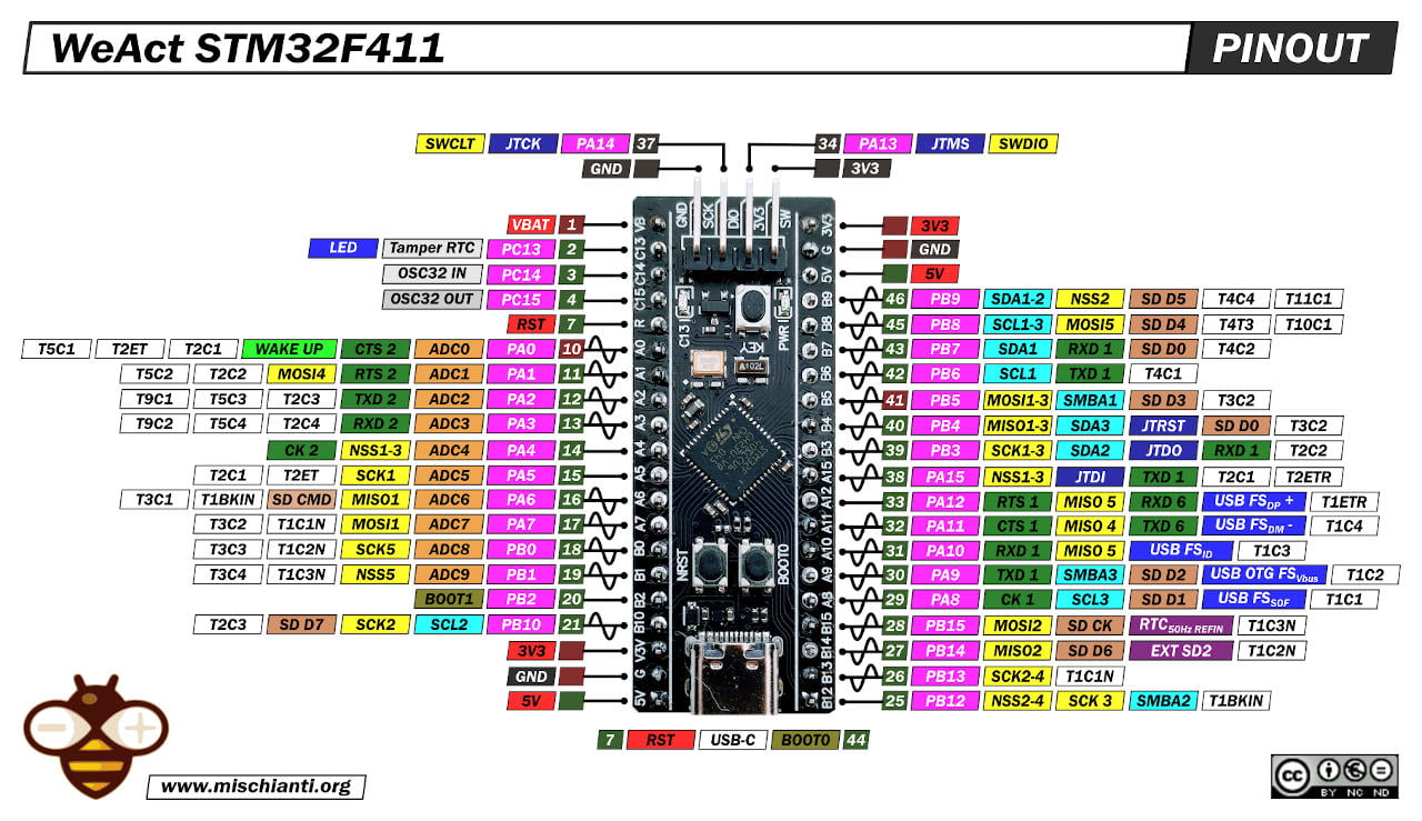
Dopo il risveglio temporizzato, l’allarme e il risveglio seriale, quello più utilizzato è il risveglio tramite una fonte esterna. In questo caso, dobbiamo prestare attenzione al pinout del nostro dispositivo per selezionare il pin corretto nella situazione corretta.
Una delle situazioni più comuni è il risveglio da una fonte esterna. In questo caso, configuriamo un pulsante.
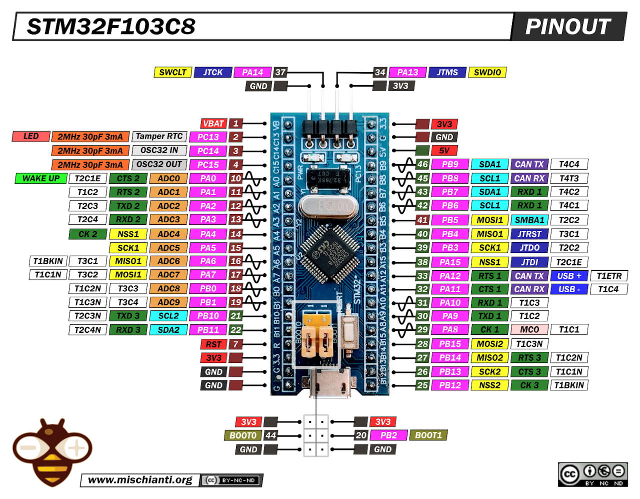
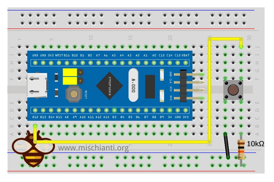
Per il primo test, configuriamo il pin PB12 come ingresso INPUT_PULLUP con un semplice pulsante con una resistenza di pull-up, quindi funziona al rilascio del pulsante (interruzione RAISING).
Controllore di interruzione esterna STM32 (risveglio da deep-sleep)
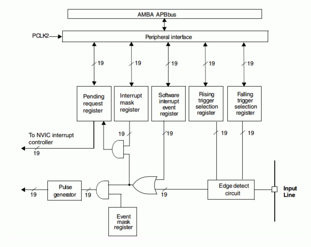
Ogni IO dell’STM32 può essere utilizzato come ingresso di interruzione esterna. EXTI (Controller di interruzione/evento esterno) gestisce 20 linee di interruzione/evento del controller. Ogni linea di interruzione/evento corrisponde a un rilevatore di edge, che può rilevare il rising edge e falling edge del segnale in ingresso. EXTI può configurare ogni linea di interruzione/evento separatamente, come un’interruzione o un evento, e gli attributi dell’evento di trigger.
Linea di interruzione esterna
Il controller di interruzione dell’STM32 supporta 19 interruzioni esterne e richieste di eventi (cioè, 19 linee di interruzione esterna). Ogni interruzione è dotata di bit di stato, e ogni interruzione/evento ha impostazioni di trigger e maschera indipendenti. Le 19 interruzioni esterne di STM32 corrispondono a 19 linee di interruzione medie:
- Linea 0~15: interruzione di ingresso corrispondente alla porta IO esterna;
- Linea 16: collegata all’uscita PVD;
- Linea 17: collegata all’evento dell’orologio di allarme RTC;
- Linea 18: collegata all’evento di risveglio USB.
Caratteristiche del Controller EXTI
Le principali caratteristiche del controller EXTI sono le seguenti:
- Trigger e maschera indipendenti su ogni linea di interruzione/evento
- Bit di stato dedicato per ogni linea di interruzione
- Generazione di fino a 20 richieste di evento/interruzione software
- Rilevazione del segnale esterno con larghezza di impulso inferiore al periodo dell’orologio APB2.
Diagramma a blocchi EXTI
Cablaggio del pin di risveglio
Qui lo STM32 e ST-Link V2 utilizzati in questo test STM32F103C8T6 STM32F401 STM32F411 ST-Link v2 ST-Link v2 official
Qui l'FTDI USB to TTL CH340G - USB to TTL FT232RL
Qui il mio multimetro Aneng SZ18
Risveglio da Deep Sleep
Ora un semplice sketch:
/**
 *	External wake up
 *
 *	In this sketch we put the STM32 on Deep Sleep than wake up It via
 *	a button.
 *	If present we use on board PB12 button, not suitable for shutdown
 *
 *	Renzo Mischianti <www.mischianti.org>
 * en: https://mischianti.org/category/tutorial/stm32-tutorial/
 * it: https://mischianti.org/it/category/guide/guida-alla-linea-di-microcontrollori-stm32/
 */

#include "STM32LowPower.h"

volatile int wakeUpCount = 1;

const int pin = PB12;

void wakedUp();

void setup() {
  Serial.begin(115200);

  pinMode(pin, INPUT_PULLUP);

  // Configure low power
  LowPower.begin();
  // Attach a wakeup interrupt on pin, calling repetitionsIncrease when the device is woken up
  // Last parameter (LowPowerMode) should match with the low power state used: in this example LowPower.sleep()
  LowPower.attachInterruptWakeup(pin, wakedUp, RISING, DEEP_SLEEP_MODE);

  Serial.println("Start low-power mode!");
  delay(1000);

  LowPower.deepSleep();

  delay(1000);
  Serial.print("Exit low-power mode! ");
  Serial.println(wakeUpCount);
}

void loop() {
	delay(100);
}

void wakedUp() {
	// This function will be called once on device wakeup
	// You can do some little operations here (like changing variables which will be used in the loop)
	// Remember to avoid calling delay() and long running functions since this functions executes in interrupt context

	Serial.println("Waked!");

	wakeUpCount ++;
}
L’output seriale è:
Start low-power mode!
Waked!
Exit low-power mode! 2
Dove la parte evidenziata è prima del rilascio del tasto del pulsante.
È necessario prestare attenzione al parametro della funzione attachInterruptWakeup.
LowPower.attachInterruptWakeup(pin, wakedUp, RISING, DEEP_SLEEP_MODE);
È importante impostare l’ultimo parametro con la corrente modalità LowPower selezionata, i valori possibili sono:
enum LP_Mode : uint8_t {
  IDLE_MODE,
  SLEEP_MODE,
  DEEP_SLEEP_MODE,
  SHUTDOWN_MODE
};
Presta attenzione, se usi un STM32F4 Black-Pill il pulsante edge non ha la resistenza di pull-up.
Se vuoi, puoi sostituire LowPower.deepSleep(); con le altre modalità LowPower.
LowPower.idle();LowPower.sleep();LowPower.shutdown();
Risveglio da Shutdown/Standby
Se provi ad utilizzare il codice sopra con lo shutdown otterrai una brutta sorpresa, Non si sveglia. Per lo shutdown (o Standby) non puoi utilizzare il pin standard, devi utilizzare il pin di wake-up.
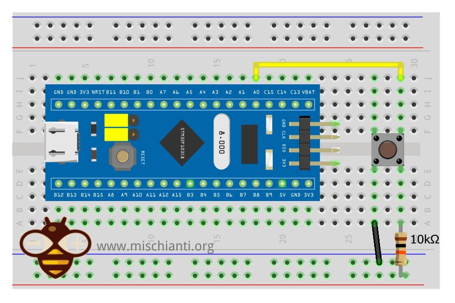
Per STM32F1 e STM32F4 è PA0, ma puoi farvi riferimento con SYS_WKUP1. Stiamo per fare alcune modifiche allo sketch per eseguire lo stesso controllo e fix.
/**
 *	External wake up
 *
 *	In this sketch we put the STM32 on shutdown than wake up It via
 *	a button.
 *	If present we use on board PA0 button (add pull-up), else set the primary
 *	System Wake Up button.
 *
 *	Renzo Mischianti <www.mischianti.org>
 * en: https://mischianti.org/category/tutorial/stm32-tutorial/
 * it: https://mischianti.org/it/category/guide/guida-alla-linea-di-microcontrollori-stm32/
 */

#include "STM32LowPower.h"
#include <STM32RTC.h>

// Pin used to trigger a wakeup
#ifndef USER_BTN
#define USER_BTN SYS_WKUP1
#endif

const int pin = USER_BTN;

void wakedUp();
bool isWakeUpPin(uint32_t pin, uint32_t mode = RISING);

void setup() {
  Serial.begin(115200);
  delay(1000);

  Serial.println("START PROGRAM!");

  pinMode(pin, INPUT_PULLUP);

  if (!isWakeUpPin(pin)) {
	  Serial.println("For Shutdown we need a wake-up pin! Check the pinout!");
	  while (true) { delay(1000); }
  }

  // Configure low power
  LowPower.begin();
  // Attach a wakeup interrupt on pin, calling repetitionsIncrease when the device is woken up
  // Last parameter (LowPowerMode) should match with the low power state used: in this example LowPower.sleep()
  LowPower.attachInterruptWakeup(pin, wakedUp, RISING, SHUTDOWN_MODE);

  Serial.println("Start shutdown mode in ");
  for (int i = 10;i>0;i--) { Serial.print(i); Serial.print(" "); } Serial.println( "OK!" );
  delay(1000);

  LowPower.shutdown();

  delay(1000);
}

void loop() {
	delay(100);
}

void wakedUp() {
	// randomly you can read this, but normally reset block every time the execution
	Serial.println("Wake-Up callback!");
}

bool isWakeUpPin(uint32_t pin, uint32_t mode)
{
  uint32_t wkup_pin = 0;
  PinName p = digitalPinToPinName(pin);
  if (p != NC) {
#ifdef PWR_WAKEUP_PIN1
    if ((p == SYS_WKUP1)
#ifdef PWR_WAKEUP_PIN1_1
        || (p == SYS_WKUP1_1)
#endif
#ifdef PWR_WAKEUP_PIN1_2
        || (p == SYS_WKUP1_2)
#endif
       ) {
      wkup_pin = PWR_WAKEUP_PIN1;
#ifdef PWR_WAKEUP_PIN1_HIGH
      if (mode != RISING) {
        wkup_pin = PWR_WAKEUP_PIN1_LOW;
      }
#endif
    }
#endif /* PWR_WAKEUP_PIN1 */
#ifdef PWR_WAKEUP_PIN2
    if ((p == SYS_WKUP2)
#ifdef PWR_WAKEUP_PIN2_1
        || (p == SYS_WKUP2_1)
#endif
#ifdef PWR_WAKEUP_PIN2_2
        || (p == SYS_WKUP2_2)
#endif
       ) {
      wkup_pin = PWR_WAKEUP_PIN2;
#ifdef PWR_WAKEUP_PIN2_HIGH
      if (mode != RISING) {
        wkup_pin = PWR_WAKEUP_PIN2_LOW;
      }
#endif
    }
#endif /* PWR_WAKEUP_PIN2 */
#ifdef PWR_WAKEUP_PIN3
    if ((p == SYS_WKUP3)
#ifdef PWR_WAKEUP_PIN3_1
        || (p == SYS_WKUP3_1)
#endif
#ifdef PWR_WAKEUP_PIN3_2
        || (p == SYS_WKUP3_2)
#endif
       ) {
      wkup_pin = PWR_WAKEUP_PIN3;
#ifdef PWR_WAKEUP_PIN3_HIGH
      if (mode != RISING) {
        wkup_pin = PWR_WAKEUP_PIN3_LOW;
      }
#endif
    }
#endif /* PWR_WAKEUP_PIN3 */
#ifdef PWR_WAKEUP_PIN4
    if ((p == SYS_WKUP4)
#ifdef PWR_WAKEUP_PIN4_1
        || (p == SYS_WKUP4_1)
#endif
#ifdef PWR_WAKEUP_PIN4_2
        || (p == SYS_WKUP4_2)
#endif
       ) {
      wkup_pin = PWR_WAKEUP_PIN4;
#ifdef PWR_WAKEUP_PIN4_HIGH
      if (mode != RISING) {
        wkup_pin = PWR_WAKEUP_PIN4_LOW;
      }
#endif
    }
#endif /* PWR_WAKEUP_PIN4 */
#ifdef PWR_WAKEUP_PIN5
    if ((p == SYS_WKUP5)
#ifdef PWR_WAKEUP_PIN5_1
        || (p == SYS_WKUP5_1)
#endif
#ifdef PWR_WAKEUP_PIN5_2
        || (p == SYS_WKUP5_2)
#endif
       ) {
      wkup_pin = PWR_WAKEUP_PIN5;
#ifdef PWR_WAKEUP_PIN5_HIGH
      if (mode != RISING) {
        wkup_pin = PWR_WAKEUP_PIN5_LOW;
      }
#endif
    }
#endif /* PWR_WAKEUP_PIN5 */
#ifdef PWR_WAKEUP_PIN6
    if ((p == SYS_WKUP6)
#ifdef PWR_WAKEUP_PIN6_1
        || (p == SYS_WKUP6_1)
#endif
#ifdef PWR_WAKEUP_PIN6_2
        || (p == SYS_WKUP6_2)
#endif
       ) {
      wkup_pin = PWR_WAKEUP_PIN6;
#ifdef PWR_WAKEUP_PIN6_HIGH
      if (mode != RISING) {
        wkup_pin = PWR_WAKEUP_PIN6_LOW;
      }
#endif
    }
#endif /* PWR_WAKEUP_PIN6 */
#ifdef PWR_WAKEUP_PIN7
    if ((p == SYS_WKUP7)
#ifdef PWR_WAKEUP_PIN7_1
        || (p == SYS_WKUP7_1)
#endif
#ifdef PWR_WAKEUP_PIN7_2
        || (p == SYS_WKUP7_2)
#endif
       ) {
      wkup_pin = PWR_WAKEUP_PIN7;
    }
#endif /* PWR_WAKEUP_PIN7 */
#ifdef PWR_WAKEUP_PIN8
    if ((p == SYS_WKUP8)
#ifdef PWR_WAKEUP_PIN8_1
        || (p == SYS_WKUP8_1)
#endif
#ifdef PWR_WAKEUP_PIN8_2
        || (p == SYS_WKUP8_2)
#endif
       ) {
      wkup_pin = PWR_WAKEUP_PIN8;
    }
#endif /* PWR_WAKEUP_PIN8 */
    return (IS_PWR_WAKEUP_PIN(wkup_pin));
  }
  return false;
}
In questo sketch, ho anche aggiunto una funzione per verificare se il pin selezionato è un pin di risveglio e, se è tutto ok, puoi risvegliare il microcontrollore.
L’output è il seguente:
START PROGRAM!
Start shutdown mode in
10 9 8 7 6 5 4 3 2 1 OK!
START PROGRAM!
Start shutdown mode in
10 9 8 7 6 5 4 3 2 1 OK!
La parte evidenziata dell’output viene scritta prima della pressione del pulsante; dopo aver premuto, il microcontrollore si riavvia dall’inizio.
Grazie
- STM32F1 Blue Pill: piedinatura, specifiche e configurazione IDE Arduino (STM32duino e STMicroelectronics)
- STM32: programmazione (STM32F1) via USB con bootloader STM32duino
- STM32: programmazione (STM32F1 STM32F4) tramite USB con bootloader HID
- STM32F4 Black Pill: pinout, specifiche e configurazione IDE Arduino
- STM32: ethernet w5500 standard (HTTP) e SSL (HTTPS)
- STM32: ethernet enc28j60 standard (HTTP) e SSL (HTTPS)
- STM32: WiFiNINA con un ESP32 come WiFi Co-Processor
- Come utilizzare la scheda SD con l’stm32 e la libreria SdFat
- STM32: memoria flash SPI FAT FS
- STM32: RTC interno, sistema orario e backup batteria (VBAT)
- STM32 LoRa
- STM32 Risparmio energetico
- STM32F1 Blue-Pill gestione clock e frequenza
- STM32F4 Black-Pill gestione clock e frequenza
- Introduzione e framework Arduino vs STM
- Libreria LowPower, cablaggio e Idle (STM Sleep).
- Sleep, deep sleep, shutdown e consumo energetico
- Sveglia da allarme RTC e Seriale
- Sveglia da sorgente esterna
- Introduzione al dominio di backup e conservazione delle variabili durante il RESET
- Registro di backup RTC e conservazione della SRAM
- STM32 invia email con allegati e SSL (come Gmail): w5500, enc28j60, SD e SPI Flash
- Server FTP su STM32 con W5500, ENC28J60, scheda SD e memoria flash SPI
- Collegamento dell’EByte E70 ai dispositivi STM32 (black/blue pill) e un semplice sketch di esempio