Dallas ds18b20 with Raspberry Pi Pico (rp2040): pull-up P-MOSFET gate and alarms
In this article, we will explore additional features that can be added to the previous project of connecting DS18B20 sensors to a Raspberry Pi Pico using the OneWire protocol.
Specifically, we will cover the use of a P-MOSFET gate as a pull-up resistor for the OneWire bus, which can improve the reliability of the communication between the sensor and the microcontroller. Additionally, we will discuss how to implement temperature alarms that can be triggered when the temperature exceeds a certain threshold.

Overall, the goal of this article is to expand on the previous project and provide more advanced techniques for using DS18B20 sensors with a Raspberry Pi Pico.
The article will cover the necessary hardware and software components, as well as provide step-by-step instructions and code examples for implementing these features. By the end of the article, readers will have a deeper understanding of how to optimize the performance of DS18B20 sensors and incorporate additional functionality into their projects.
Features
- Unique 1-Wire® Interface Requires Only One Port Pin for Communication
- Reduce Component Count with Integrated Temperature Sensor and EEPROM
- Measures Temperatures from -55°C to +125°C (-67°F to +257°F)
- ±0.5°C Accuracy from -10°C to +85°C
- Programmable Resolution from 9 Bits to 12 Bits
- No External Components Required
- Parasitic Power Mode Requires Only 2 Pins for Operation (DQ and GND)
- Simplifies Distributed Temperature-Sensing Applications with Multidrop Capability
- Each Device Has a Unique 64-Bit Serial Code Stored in On-Board ROM
- Flexible User-Definable Nonvolatile (NV) Alarm Settings with Alarm Search Command Identifies Devices with Temperatures Outside Programmed Limits
- Available in 8-Pin SO (150 mils), 8-Pin µSOP, and 3-Pin TO-92 Packages
Datasheet
Pinout
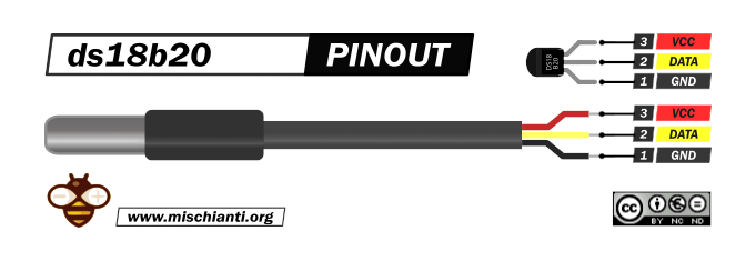
The sensor has more variants, but the wiring remains the same.
GND: connect to GND.
DATA: One-Wire Data bus.
VCC: power supply (3,3 – 5 V), but in parasite mode, you can connect to GND.
Here the sensor AliExpress
Parasite mode issues
The 1-Wire communication protocol not only facilitates communication but also provides operating power for the slaves. The slaves draw power from the bus when the voltage on the bus is greater than the voltage on their internal energy storage capacitor.
However, in networks with too many slaves, the current delivered by the master may not be sufficient to maintain operating voltage in the slaves, causing intermittent failures that are data-dependent.
The worst-case scenario for parasite power is a long sequence of zero bits issued by the master, as the bus spends most of its time in the low state, and there is little opportunity to recharge the slaves.
As the voltage in each slave drops, the slave’s ability to drive the bus decreases, eventually leading to a reset state where the slave stops responding.
When the slave receives sufficient operating voltage again, it will issue a presence pulse, which can corrupt other bus activity.
A possible solution is shown in the image above, the 1-Wire bus must be switched to the strong pullup within 10µs (max) after temperature conversions, and the bus must be held high by the pullup for the duration of the conversion or data transfer. No other activity can take place on the 1-Wire bus while the pullup is enabled.
The DS18B20 can also be powered by the conventional method of connecting an external power supply to the VDD pin, as shown. The advantage of this method is that the MOSFET pull-up is not required, and the 1-Wire bus is free to carry other traffic during the temperature conversion time.
Wiring
The One-Wire library Is a standard for all microcontrollers, so the device can be used with many microcontrollers. We already show the connection of the single sensor, and now we are going to connect and manage multiple sensors.
If you need to connect only one sensor, refer to the previous article, “Dallas ds18b20 with Raspberry Pi Pico (rp2040): introduction and parasite mode”.
Raspberry Pi Pico
Here is the pinout of Raspberry Pi Pico prototype boards.
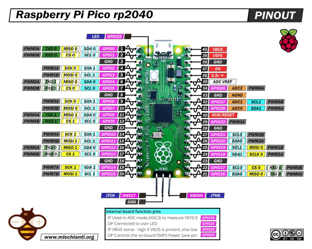
Or WeAct variant:

Here some rp2040 prototype board Official Pi Pico - Official Pi Pico W - Waveshare rp2040-zero - WeAct Studio rp2040
Normal mode
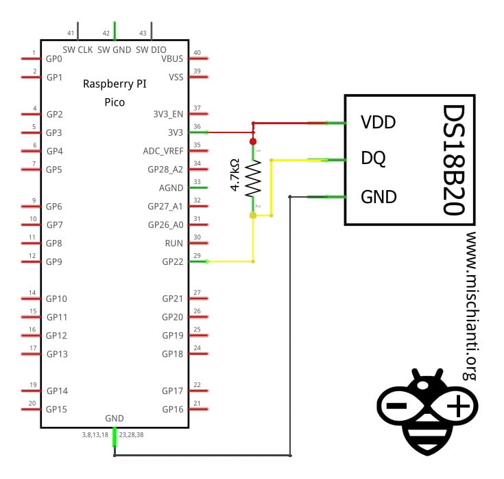
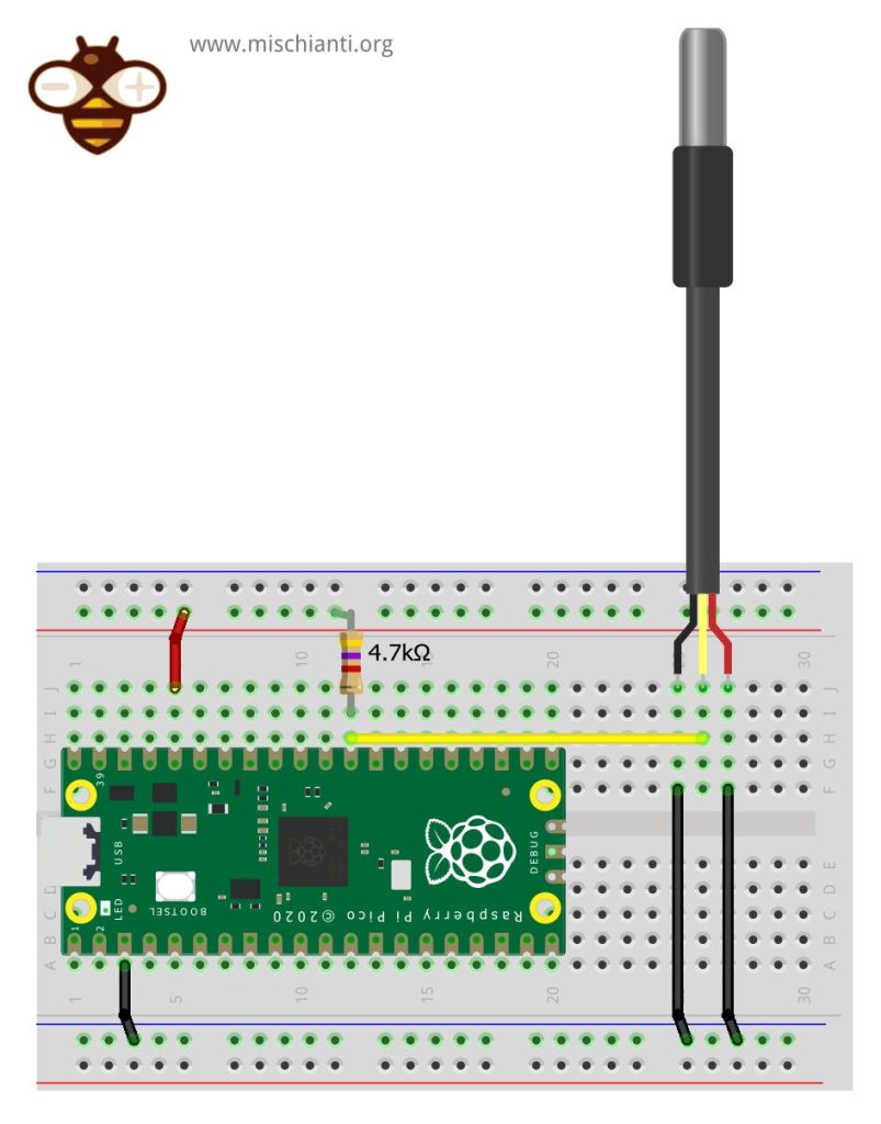
In normal mode, we are going to use a power line at 3.3v, so the connection becomes like so.
The connection is very simple.
| esp32 | ds18b20 |
|---|---|
| GND | GND |
| 3.3v | VCC |
| D22 pulled-up | DATA |
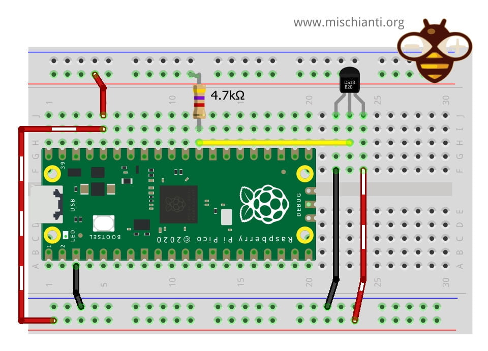
Schema
Here is the simple schema.
Parasite mode
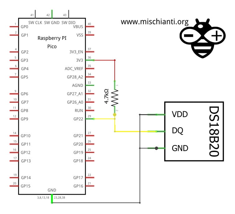
In the parasite mode, you are going to put GND also in the VCC line of the sensor, and It gets the power from the Data line.
| esp32 | ds18b20 |
|---|---|
| GND | GND |
| GND | VCC |
| D22 pulled-up | DATA |
Next, we will analyze this modality in-depth, but you don’t need more information now.
Schema
Here is the schema.
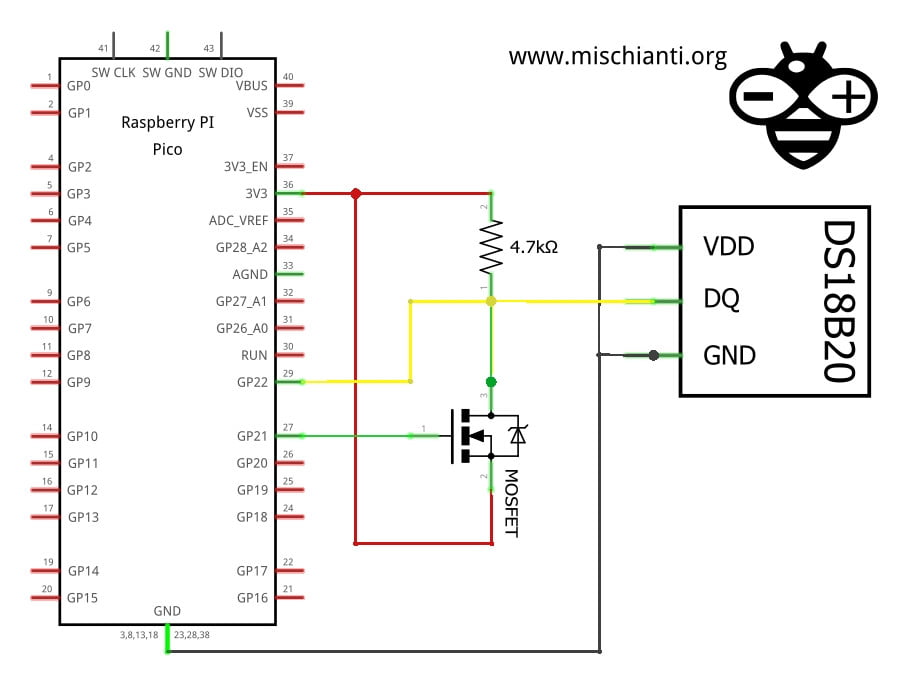
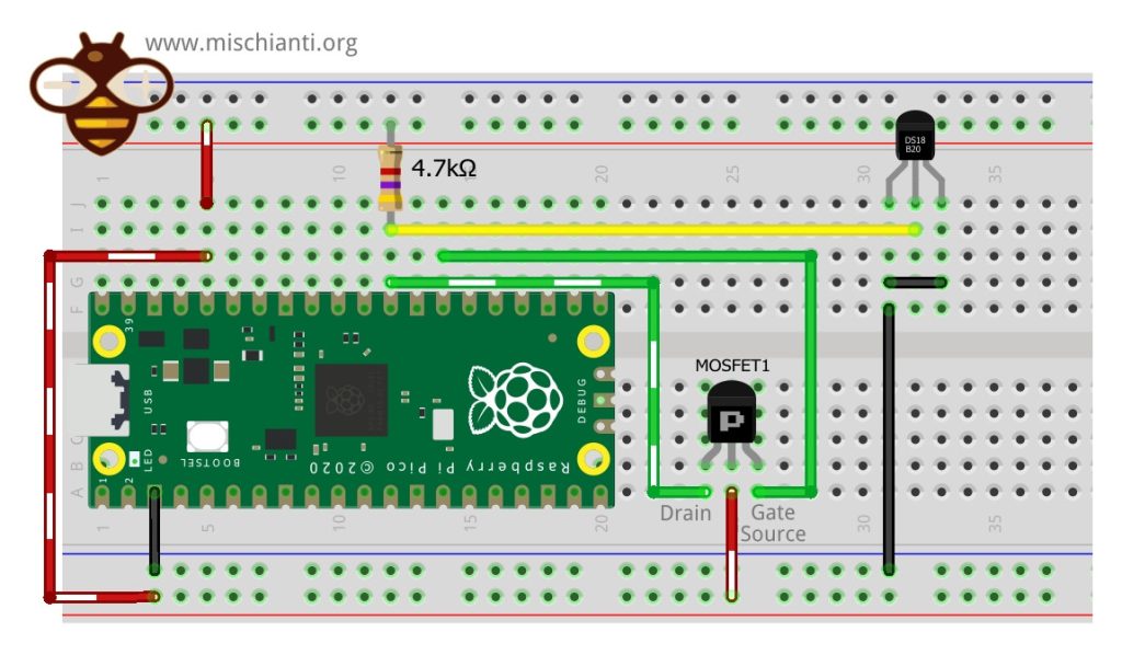
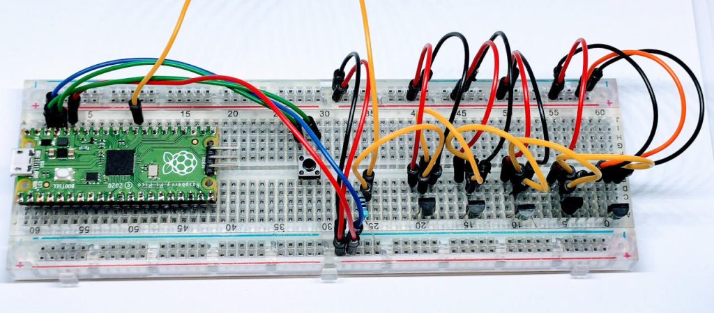
Strong pull-up P-MOSFET gate
The use of a P-MOSFET makes the strong pull-up. Here is a simple wiring example.
| rp2040 | ds18b20 |
|---|---|
| GND | GND |
| GND | VCC |
| D22 pulled-up | DATA |
| rp2040 | P-MOSFET | ds18b20 |
|---|---|---|
| D21 | Gate | |
| VCC | Source | |
| Drain | DATA |
For a 1-wire circuit with a strong pull-up, the MOSFET should be connected as follows:
- The drain of the MOSFET should be connected to the 1-wire data line of the device, i.e., the connection of the ds18b20.
- The source of the MOSFET should be connected to a positive power supply voltage.
- The gate of the MOSFET should be connected to a pin of the microcontroller configured as an output.
- The microcontroller pin that controls the MOSFET gate should be set to HIGH to activate the strong pull-up and LOW to deactivate it.
It is important to note that the strong pull-up should only be activated when the microcontroller needs to read data from the ds18b20. When data is not being read, the strong pull-up should be deactivated to prevent overheating of the ds18b20.
Library
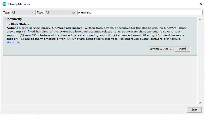
Now, when I write this article, there is a bug in the most famous library OneWire, so I insert the link to this library, so don’t use It.
Use OneWireNg not the standard OneWire library
Don’t use it until the bug is fixed.
First of all, you must remember that this sensor uses the One-Wire protocol, so you must add the OneWire library.
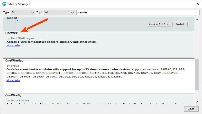
Use this for now
After that, you must install a library that implements the protocol and sensor features.
I chose the most widely used, the DallasTemperature (in the past Dallas, now Maxim).
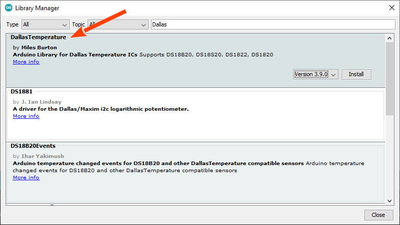
Devices supported
As described in the repository, this library supports the following devices :
- DS18B20
- DS18S20 (some problems on this device)
- DS1822
- DS1820
- MAX31820
- MAX31850
You will need a pull-up resistor of about 4.7KOhm between the 1-Wire data line and your VCC. if you are using the DS18B20, you can use parasite mode, and you can put to GND the VCC as described.
Troubleshooting
In case of temperature conversion problems (the result is -85), a strong pull-up setup may be necessary. See section Powering the DS18B20 in DS18B20 datasheet (page 7) and use DallasTemperature(OneWire*, uint8_t) constructor.
Powering the DS18B20 (normal/parasite)
The DS18B20 can be powered by an external supply on the VDD pin, or it can operate in “parasite power” mode, which allows the DS18B20 to function without a local external supply (you connect the VDD to the GND). DS18B20 “steals” power from the 1-Wire bus via the DQ pin when the bus is high. The stolen charge powers the DS18B20 while the bus is high, and some of the charges are stored on the parasite power capacitor (CPP) to provide power when the bus is low.
But when the DS18B20 performs temperature conversions or copies data from the scratchpad memory to EEPROM, the operating current can be as high as 1.5mA. This current can cause an unacceptable voltage drop across the weak 1-Wire pullup resistor and is more current than CPP can supply.
Strong pull-up for parasite mode
To assure that the DS18B20 has sufficient current supply, it is necessary to provide a strong pullup on the 1-Wire bus whenever temperature conversions occur or data is being copied from the scratchpad to EEPROM.
This can be accomplished by using a MOSFET to pull the bus directly to the rail.
The 1-Wire bus must be switched to the strong pullup within 10µs (max) after temperature conversions, and the bus must be held high by the pullup for the duration of the conversion or data transfer. No other activity can take place on the 1-Wire bus while the pullup is enabled.
The DS18B20 can also be powered by the conventional method of connecting an external power supply to the VDD pin, as shown. The advantage of this method is that the MOSFET pull-up is not required, and the 1-Wire bus is free to carry other traffic during the temperature conversion time.
The use of parasite power is not recommended for temperatures above +100°C since the DS18B20 may not be able to sustain communications due to the higher leakage currents that can exist at these temperatures.
Code
Here are some examples to better understand.
Using the library to manage a strong pull-up
Here is an example code for Raspberry Pi Pico that uses strong pull-up to read in series a list of ds18b20:
#include <OneWire.h>
#include <DallasTemperature.h>

// Data wire is plugged into port 2 on the Arduino, while external pullup P-MOSFET gate into port 3
#define ONE_WIRE_BUS    D22
#define ONE_WIRE_PULLUP D21

// Setup a oneWire instance to communicate with any OneWire devices (not just Maxim/Dallas temperature ICs)
OneWire oneWire(ONE_WIRE_BUS);

// Pass our oneWire reference to Dallas Temperature.
DallasTemperature sensors(&oneWire, ONE_WIRE_PULLUP);

void setup(void)
{
  // start serial port
  Serial.begin(9600);
  Serial.println("Dallas Temperature IC Control Library Demo");

  // Start up the library
  sensors.begin();
}

void loop(void)
{
  // call sensors.requestTemperatures() to issue a global temperature
  // request to all devices on the bus
  Serial.print("Requesting temperatures...");
  sensors.requestTemperatures(); // Send the command to get temperatures
  Serial.println("DONE");

 for(int i=0;i<sensors.getDeviceCount();i++) {
   Serial.println("Temperature for Device "+String(i)+" is: " + String(sensors.getTempCByIndex(i)));
 }
}
You can see in the highlighted code how to pass the pin to manage MOSFET, and this can be very useful when you have a very long wire.
Using alarm
An interesting feature is the management of alarms. This feature is quite simple; you can set a max and a min value, and when It happens, a function return true or a callback is called.
Manage an alarm on a single ds18b20
The sketch initializes the sensor and sets two alarm temperature thresholds, one for a high-temperature alarm and one for a low-temperature alarm. The sketch continuously requests temperature readings from the sensor and checks for alarm conditions. If an alarm condition is detected, the sketch outputs an alert message containing the device address and temperature reading.
/**
 * From the original example of the library.
 *
 * Here a manual management of alarm without an handler.
 *
 * by Renzo Mischianti <www.mischianti.org>
 *
 * https://mischianti.org
 */

#include <OneWire.h>
#include <DallasTemperature.h>

// Data wire is plugged into port D22
#define ONE_WIRE_BUS D22

// Setup a oneWire instance to communicate with any OneWire devices (not just Maxim/Dallas temperature ICs)
OneWire oneWire(ONE_WIRE_BUS);

// Pass our oneWire reference to Dallas Temperature.
DallasTemperature sensors(&oneWire);

// arrays to hold device addresses
DeviceAddress insideThermometer;

void setup(void)
{
  // start serial port
  Serial.begin(115200);
  Serial.println("Dallas Temperature IC Control Library Demo");

  // Start up the library
  sensors.begin();

  // locate devices on the bus
  Serial.print("Found ");
  Serial.print(sensors.getDeviceCount(), DEC);
  Serial.println(" devices.");

  // search for devices on the bus and assign based on an index.
  if (!sensors.getAddress(insideThermometer, 0)) Serial.println("Unable to find address for Device 0");

  // show the addresses we found on the bus
  Serial.print("Device 0 Address: ");
  printAddress(insideThermometer);
  Serial.println();

  Serial.print("Device 0 Alarms: ");
  printAlarms(insideThermometer);
  Serial.println();

  Serial.println("Setting alarm temps...");

  // alarm when temp is higher than 22C
  sensors.setHighAlarmTemp(insideThermometer, 22);

  // alarm when temp is lower than 20C
  sensors.setLowAlarmTemp(insideThermometer, 20);

  Serial.print("New Device 0 Alarms: ");
  printAlarms(insideThermometer);
  Serial.println();

}

// function to print a device address
void printAddress(DeviceAddress deviceAddress)
{
  for (uint8_t i = 0; i < 8; i++)
  {
    if (deviceAddress[i] < 16) Serial.print("0");
    Serial.print(deviceAddress[i], HEX);
  }
}

// function to print the temperature for a device
void printTemperature(DeviceAddress deviceAddress)
{
  float tempC = sensors.getTempC(deviceAddress);
  Serial.print("Temp C: ");
  Serial.print(tempC);
  Serial.print(" Temp F: ");
  Serial.print(DallasTemperature::toFahrenheit(tempC));
}

void printAlarms(uint8_t deviceAddress[])
{
  char temp;
  temp = sensors.getHighAlarmTemp(deviceAddress);
  Serial.print("High Alarm: ");
  Serial.print(temp, DEC);
  Serial.print("C/");
  Serial.print(DallasTemperature::toFahrenheit(temp));
  Serial.print("F | Low Alarm: ");
  temp = sensors.getLowAlarmTemp(deviceAddress);
  Serial.print(temp, DEC);
  Serial.print("C/");
  Serial.print(DallasTemperature::toFahrenheit(temp));
  Serial.print("F");
}

// main function to print information about a device
void printData(DeviceAddress deviceAddress)
{
  Serial.print("Device Address: ");
  printAddress(deviceAddress);
  Serial.print(" ");
  printTemperature(deviceAddress);
  Serial.println();
}

void checkAlarm(DeviceAddress deviceAddress)
{
  if (sensors.hasAlarm(deviceAddress))
  {
    Serial.print("ALARM: ");
    printData(deviceAddress);
  }
}

void loop(void)
{
  // call sensors.requestTemperatures() to issue a global temperature
  // request to all devices on the bus
  Serial.print("Requesting temperatures...");
  sensors.requestTemperatures();
  Serial.print("DONE --> ");
  printData(insideThermometer);

  // Method 1:
  // check each address individually for an alarm condition
  checkAlarm(insideThermometer);
/*
  // Alternate method:
  // Search the bus and iterate through addresses of devices with alarms

  // space for the alarm device's address
  DeviceAddress alarmAddr;

  Serial.println("Searching for alarms...");

  // resetAlarmSearch() must be called before calling alarmSearch()
  sensors.resetAlarmSearch();

  // alarmSearch() returns 0 when there are no devices with alarms
  while (sensors.alarmSearch(alarmAddr))
  {
    Serial.print("ALARM: ");
    printData(alarmAddr);
  }
*/

  delay(2000);
}
Here is the result.
Dallas Temperature IC Control Library Demo
Found 5 devices.
Device 0 Address: 28FF640E6C63D015
Device 0 Alarms: High Alarm: 22C/71.60F | Low Alarm: 21C/69.80F
Setting alarm temps...
New Device 0 Alarms: High Alarm: 22C/71.60F | Low Alarm: 20C/68.00F
Requesting temperatures...DONE --> Device Address: 28FF640E6C63D015 Temp C: 21.12 Temp F: 70.03
Requesting temperatures...DONE --> Device Address: 28FF640E6C63D015 Temp C: 21.12 Temp F: 70.03
Requesting temperatures...DONE --> Device Address: 28FF640E6C63D015 Temp C: 21.19 Temp F: 70.14
Requesting temperatures...DONE --> Device Address: 28FF640E6C63D015 Temp C: 21.12 Temp F: 70.03
Requesting temperatures...DONE --> Device Address: 28FF640E6C63D015 Temp C: 21.12 Temp F: 70.03
Requesting temperatures...DONE --> Device Address: 28FF640E6C63D015 Temp C: 21.19 Temp F: 70.14
Requesting temperatures...DONE --> Device Address: 28FF640E6C63D015 Temp C: 21.12 Temp F: 70.03
Requesting temperatures...DONE --> Device Address: 28FF640E6C63D015 Temp C: 21.19 Temp F: 70.14
Requesting temperatures...DONE --> Device Address: 28FF640E6C63D015 Temp C: 21.19 Temp F: 70.14
Requesting temperatures...DONE --> Device Address: 28FF640E6C63D015 Temp C: 22.37 Temp F: 72.28
ALARM: Device Address: 28FF640E6C63D015 Temp C: 22.37 Temp F: 72.28
Requesting temperatures...DONE --> Device Address: 28FF640E6C63D015 Temp C: 22.62 Temp F: 72.72
ALARM: Device Address: 28FF640E6C63D015 Temp C: 22.62 Temp F: 72.72
Requesting temperatures...DONE --> Device Address: 28FF640E6C63D015 Temp C: 22.37 Temp F: 72.28
ALARM: Device Address: 28FF640E6C63D015 Temp C: 22.37 Temp F: 72.28
Requesting temperatures...DONE --> Device Address: 28FF640E6C63D015 Temp C: 22.19 Temp F: 71.94
ALARM: Device Address: 28FF640E6C63D015 Temp C: 22.19 Temp F: 71.94
Requesting temperatures...DONE --> Device Address: 28FF640E6C63D015 Temp C: 21.87 Temp F: 71.37
Requesting temperatures...DONE --> Device Address: 28FF640E6C63D015 Temp C: 21.75 Temp F: 71.15
Requesting temperatures...DONE --> Device Address: 28FF640E6C63D015 Temp C: 21.62 Temp F: 70.92
Manage single Alarm handler for all sensors
Here is an example with 2 sensors and the same alarm settings. When the alarm was raised, the handler was called for every sensor.
/**
 * Here 2 ds18b20 with the same alarm settings, and an handler for the alarm.
 *
 * When the Alarm is raised, the handler is called for every sensor in alarm state.
 *
 * by Renzo Mischianti <www.mischianti.org>
 *
 * https://mischianti.org
 *
 */

#include <OneWire.h>
#include <DallasTemperature.h>

// Data wire is plugged into port D22
#define ONE_WIRE_BUS D22

// Setup a oneWire instance to communicate with any OneWire devices (not just Maxim/Dallas temperature ICs)
OneWire oneWire(ONE_WIRE_BUS);

// Pass our oneWire reference to Dallas Temperature.
DallasTemperature sensors(&oneWire);

// arrays to hold device addresses
DeviceAddress thermometer1, thermometer2;

// function that will be called when an alarm condition exists during DallasTemperatures::processAlarms();
void newAlarmHandler(const uint8_t* deviceAddress)
{
  Serial.println("Alarm Handler Start");
  printAlarmInfo(deviceAddress);
  printTemp(deviceAddress);
  Serial.println();
  Serial.println("Alarm Handler Finish");
}

void printCurrentTemp(DeviceAddress deviceAddress)
{
  printAddress(deviceAddress);
  printTemp(deviceAddress);
}

void printAddress(const DeviceAddress deviceAddress)
{
  Serial.print("Address: ");
  for (uint8_t i = 0; i < 8; i++)
  {
    if (deviceAddress[i] < 16) Serial.print("0");
    Serial.print(deviceAddress[i], HEX);
  }
  Serial.print(" ");
}

void printTemp(const DeviceAddress deviceAddress)
{
  float tempC = sensors.getTempC(deviceAddress);
  if (tempC != DEVICE_DISCONNECTED_C)
  {
    Serial.print("Current Temp C: ");
    Serial.print(tempC);
  }
  else Serial.print("DEVICE DISCONNECTED");
  Serial.print(" ");
}

void printAlarmInfo(const DeviceAddress deviceAddress)
{
  char temp;
  printAddress(deviceAddress);
  temp = sensors.getHighAlarmTemp(deviceAddress);
  Serial.print("High Alarm: ");
  Serial.print(temp, DEC);
  Serial.print("C");
  Serial.print(" Low Alarm: ");
  temp = sensors.getLowAlarmTemp(deviceAddress);
  Serial.print(temp, DEC);
  Serial.print("C");
  Serial.print(" ");
}

void setup(void)
{
  // start serial port
  Serial.begin(115200);
  Serial.println("Dallas Temperature IC Control Library Demo");

  // Start up the library
  sensors.begin();

  // locate devices on the bus
  Serial.print("Found ");
  Serial.print(sensors.getDeviceCount(), DEC);
  Serial.println(" devices.");

  // search for devices on the bus and assign based on an index
  if (!sensors.getAddress(thermometer1, 0)) Serial.println("Unable to find address for Device 0");
  // search for devices on the bus and assign based on an index
  if (!sensors.getAddress(thermometer2, 1)) Serial.println("Unable to find address for Device 1");

  Serial.print("Device thermometer1 ");
  printAlarmInfo(thermometer1);
  Serial.println();

  // set alarm ranges
  Serial.println("Setting alarm temps...");
  sensors.setHighAlarmTemp(thermometer1, 22);
  sensors.setLowAlarmTemp(thermometer1, 20);

  Serial.print("New thermometer1 ");
  printAlarmInfo(thermometer1);
  Serial.println();

  Serial.print("Device thermometer2 ");
  printAlarmInfo(thermometer2);
  Serial.println();

  // set alarm ranges
  Serial.println("Setting alarm temps...");
  sensors.setHighAlarmTemp(thermometer2, 22);
  sensors.setLowAlarmTemp(thermometer2, 20);

  Serial.print("New thermometer2 ");
  printAlarmInfo(thermometer2);
  Serial.println();

  // attach alarm handler
  sensors.setAlarmHandler(&newAlarmHandler);

}

void loop(void)
{
  // ask the devices to measure the temperature
  sensors.requestTemperatures();

  // if an alarm condition exists as a result of the most recent
  // requestTemperatures() request, it exists until the next time
  // requestTemperatures() is called AND there isn't an alarm condition
  // on the device
  if (sensors.hasAlarm())
  {
    Serial.println("Oh noes!  There is at least one alarm on the bus.");
  }

  // call alarm handler function defined by sensors.setAlarmHandler
  // for each device reporting an alarm
  sensors.processAlarms();

  if (!sensors.hasAlarm())
  {
    // just print out the current temperature
	    printCurrentTemp(thermometer1);
	    Serial.print(" - ");
	    printCurrentTemp(thermometer2);
	    Serial.println();
  }

  delay(1000);
}
To set the handler, there is a specified function:
  // attach alarm handler
  sensors.setAlarmHandler(&newAlarmHandler);
This handler is for all Sensors, and It’s processed with this function:
  // call alarm handler function defined by sensors.setAlarmHandler
  // for each device reporting an alarm
  sensors.processAlarms();
In this case, the 2 sensors aren’t raised at the same time, first only the thermometer with 28FF640E6C6F7A89 address, then all together.
Dallas Temperature IC Control Library Demo
Found 5 devices.
Device thermometer1 Address: 28FF640E6C63D015 High Alarm: 22C Low Alarm: 20C
Setting alarm temps...
New thermometer1 Address: 28FF640E6C63D015 High Alarm: 22C Low Alarm: 20C
Device thermometer2 Address: 28FF640E6C6F7A89 High Alarm: 22C Low Alarm: 20C
Setting alarm temps...
New thermometer2 Address: 28FF640E6C6F7A89 High Alarm: 22C Low Alarm: 20C
Address: 28FF640E6C63D015 Current Temp C: 20.75  - Address: 28FF640E6C6F7A89 Current Temp C: 20.69
Address: 28FF640E6C63D015 Current Temp C: 20.75  - Address: 28FF640E6C6F7A89 Current Temp C: 20.69
Address: 28FF640E6C63D015 Current Temp C: 20.75  - Address: 28FF640E6C6F7A89 Current Temp C: 20.69
Address: 28FF640E6C63D015 Current Temp C: 20.75  - Address: 28FF640E6C6F7A89 Current Temp C: 20.69
Address: 28FF640E6C63D015 Current Temp C: 20.75  - Address: 28FF640E6C6F7A89 Current Temp C: 20.69
Address: 28FF640E6C63D015 Current Temp C: 20.75  - Address: 28FF640E6C6F7A89 Current Temp C: 20.69
Address: 28FF640E6C63D015 Current Temp C: 20.75  - Address: 28FF640E6C6F7A89 Current Temp C: 20.69
Address: 28FF640E6C63D015 Current Temp C: 20.75  - Address: 28FF640E6C6F7A89 Current Temp C: 20.69
Address: 28FF640E6C63D015 Current Temp C: 20.75  - Address: 28FF640E6C6F7A89 Current Temp C: 20.69
Address: 28FF640E6C63D015 Current Temp C: 20.75  - Address: 28FF640E6C6F7A89 Current Temp C: 20.69
Address: 28FF640E6C63D015 Current Temp C: 20.75  - Address: 28FF640E6C6F7A89 Current Temp C: 20.69
Address: 28FF640E6C63D015 Current Temp C: 20.75  - Address: 28FF640E6C6F7A89 Current Temp C: 20.69
Address: 28FF640E6C63D015 Current Temp C: 20.75  - Address: 28FF640E6C6F7A89 Current Temp C: 20.69
Address: 28FF640E6C63D015 Current Temp C: 21.06  - Address: 28FF640E6C6F7A89 Current Temp C: 21.50
Oh noes!  There is at least one alarm on the bus.
Alarm Handler Start
Address: 28FF640E6C6F7A89 High Alarm: 22C Low Alarm: 20C Current Temp C: 22.62
Alarm Handler Finish
Oh noes!  There is at least one alarm on the bus.
Alarm Handler Start
Address: 28FF640E6C63D015 High Alarm: 22C Low Alarm: 20C Current Temp C: 22.56
Alarm Handler Finish
Alarm Handler Start
Address: 28FF640E6C6F7A89 High Alarm: 22C Low Alarm: 20C Current Temp C: 23.44
Alarm Handler Finish
Oh noes!  There is at least one alarm on the bus.
Alarm Handler Start
Address: 28FF640E6C63D015 High Alarm: 22C Low Alarm: 20C Current Temp C: 23.12
Alarm Handler Finish
Alarm Handler Start
Address: 28FF640E6C6F7A89 High Alarm: 22C Low Alarm: 20C Current Temp C: 23.62
Alarm Handler Finish
Oh noes!  There is at least one alarm on the bus.
Alarm Handler Start
Address: 28FF640E6C63D015 High Alarm: 22C Low Alarm: 20C Current Temp C: 22.94
Alarm Handler Finish
Alarm Handler Start
Address: 28FF640E6C6F7A89 High Alarm: 22C Low Alarm: 20C Current Temp C: 23.31
Alarm Handler Finish
Oh noes!  There is at least one alarm on the bus.
Alarm Handler Start
Address: 28FF640E6C63D015 High Alarm: 22C Low Alarm: 20C Current Temp C: 22.75
Alarm Handler Finish
Alarm Handler Start
Address: 28FF640E6C6F7A89 High Alarm: 22C Low Alarm: 20C Current Temp C: 23.06
Alarm Handler Finish
Oh noes!  There is at least one alarm on the bus.
Alarm Handler Start
Address: 28FF640E6C63D015 High Alarm: 22C Low Alarm: 20C Current Temp C: 22.56
Alarm Handler Finish
Alarm Handler Start
Address: 28FF640E6C6F7A89 High Alarm: 22C Low Alarm: 20C Current Temp C: 22.81
Alarm Handler Finish
Thanks
- Raspberry Pi Pico and rp2040 boards: pinout, specs, and Arduino IDE configuration
- Raspberry Pi Pico and rp2040 boards: integrated LittleFS filesystem
- Raspberry Pi Pico and rp2040 board: ethernet w5500 with plain (HTTP) and SSL (HTTPS) requests
- Raspberry Pi Pico and rp2040 boards: WiFiNINA with ESP32 WiFi Co-Processor
- Raspberry Pi Pico and rp2040 boards: how to use SD card
- Dallas ds18b20
- Connecting the EByte E70 to Raspberry Pi Pico (rp2040) devices and a simple sketch example