i2c Arduino SAMD MKR: interfaccia aggiuntiva SERCOM, rete e scanner di indirizzi
Adoro il protocollo I2C, e quando ho bisogno di un sensore, ogni volta che provo a trovarne uno con questo protocollo, ho anche scritto delle librerie per vari sensori che usano l’I2C. Quindi voglio scrivere alcuni articoli che spieghino (Arduino, Arduino SAMD MKR, esp8266 e esp32) alcune caratteristiche interessanti e cercherò di spiegare come risolvere i problemi che puoi avere quando lavori con più dispositivi I2C.
È il momento di esaminare l’interfaccia SERCOM, con un particolare interesse per l’interfaccia I2C, di schede di nuova generazione come Arduino Zero, MKR e altre.
Introduzione al protocollo I2C
I2C (Inter-Integrated Circuit, eye-squared-C) ed è noto in alternativa come I2C o IIC. È un bus di comunicazione seriale sincrono, multi-master, multi-slave, a commutazione di pacchetto, single-ended. Inventato nel 1982 da Philips Semiconductors. È ampiamente utilizzato per collegare circuiti integrati periferici a bassa velocità a processori e microcontrollori nelle comunicazioni intraschede a breve distanza. (cit.WiKi)
Velocità
L’I2C supporta 100 kbps, 400 kbps, 3,4 Mbps. Alcune varianti supportano anche 10Kbps e 1Mbps.
| Mode | Maximum speed | Maximum capacitance | Drive | Direction |
|---|---|---|---|---|
| Standard-mode (Sm) | 100 kbit/s | 400 pF | Open drain | Bidirectional |
| Fast-mode (Fm) | 400 kbit/s | 400 pF | Open drain | Bidirectional |
| Fast-mode Plus (Fm+) | 1 Mbit/s | 550 pF | Open drain | Bidirectional |
| High-speed mode (Hs) | 1.7 Mbit/s | 400 pF | Open drain | Bidirectional |
| High-speed mode (Hs) | 3.4 Mbit/s | 100 pF | Open drain | Bidirectional |
| Ultra Fast-mode (UFm) | 5 Mbit/s | Push-pull | Unidirectional |
Interfaccia
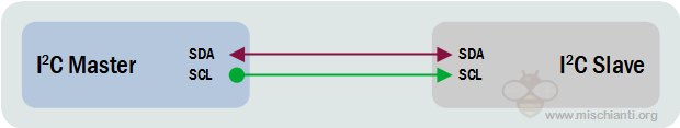
Come la comunicazione UART, I2C utilizza solo due fili per trasmettere dati tra dispositivi:
- SDA (Serial Data) – La linea per il master e lo slave per inviare e ricevere dati.
- SCL (Serial Clock) – La linea che trasporta il segnale di clock (segnale di clock comune tra più master e più slave).
L’I2C è un protocollo di comunicazione seriale, quindi i dati vengono trasferiti bit per bit lungo un singolo filo (la linea SDA).
Come lo SPI, l’I2C è sincrono, quindi l’output dei bit è sincronizzato con il campionamento dei bit da un segnale di clock condiviso tra il master e lo slave. Il segnale di clock è sempre controllato dal master.
Ci saranno più slave e più master e tutti i master possono comunicare con tutti gli slave.

- Inizio: La linea SDA passa da un livello di alta tensione a un livello di bassa tensione prima che la linea SCL passi da un livello alto a basso.
- Stop: la linea SDA passa da un livello di bassa tensione a un livello di alta tensione dopo che la linea SCL è passata da un livello basso ad alto.
- Frame di indirizzo: una sequenza di 7 o 10 bit univoca per ogni slave identifica lo slave quando il master vuole parlargli.
- Bit di lettura/scrittura: un singolo bit che specifica se il master sta inviando dati allo slave (livello di bassa tensione) o richiedendo dati da esso (livello di alta tensione).
- Bit ACK/NACK: ogni frame in un messaggio è seguito da un bit di riconoscimento/non riconoscimento. Se un frame di indirizzo o un frame di dati è stato ricevuto correttamente, un bit ACK viene restituito al mittente dal dispositivo ricevente.
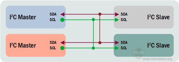
Connessioni dei dispositivi
Poiché l’I2C utilizza l’indirizzamento, più slave possono essere controllati da un unico master. È possibile collegare/indirizzare fino a 27 dispositivi slave nel circuito di interfaccia I2C. Con un indirizzo a 7 bit sono disponibili 128 (27) indirizzi univoci. L’utilizzo di indirizzi a 10 bit è raro ma fornisce 1.024 (210) indirizzi univoci.
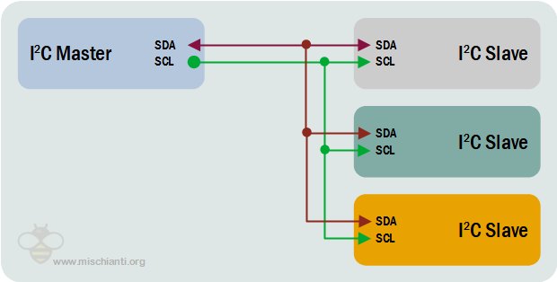
È possibile collegare più master a un singolo slave o più slave. Il problema con più master nello stesso sistema si verifica quando due master tentano di inviare o ricevere dati contemporaneamente sulla linea SDA. Ogni master deve rilevare se la linea SDA è bassa o alta prima di trasmettere un messaggio per risolvere questo problema. Se la linea SDA è bassa, significa che un altro master ha il controllo del bus e il master deve attendere per inviare il messaggio. Se la linea SDA è alta, è possibile trasmettere il messaggio. Per collegare più master a più slave.
How to per l’Arduino SAMD MKR
Qui le nuove schede Arduino Amazon Arduino MKR WiFi 1010
SAMD21 può gestire interfacce seriali multiple (e configurabili) con SERCOM (Serial Communication), che è una configurazione seriale multiplexata. Ti consente di selezionare varie funzioni seriali per la maggior parte dei tuoi pin. Ad esempio, l’ATmega328 ha UART (RX/TX) su una coppia di pin, I2C (SDA/SCL) su un altro set e SPI (MOSI, MISO, SCK) su un altro set. Il SAMD21 ha 5 diverse porte interne che puoi configurare per utilizzare qualsiasi combinazione di UART, I2C e SPI.
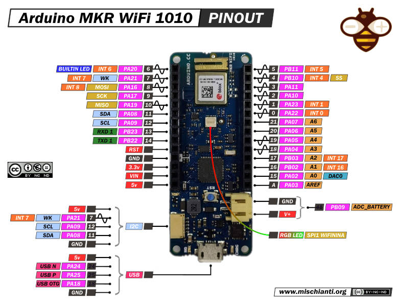
I microcontrollori Arduino SAMD hanno sei moduli seriali interni che possono essere configurati individualmente e solo quattro di essi sono già configurati. Gli altri due sono disponibili per la mappatura su pin specifici.
| SERCOM | Protocol | Pins |
|---|---|---|
| SERCOM 0 | I2C | SDA: PIN 11 SCL: PIN 12 |
| SERCOM 1 | SPI | MOSI: PIN 8 SCK: PIN 9 MISO: PIN 10 |
| SERCOM 5 | UART | RX: PIN 13 TX: PIN 14 |
Internamente di solito, SERCOM2 viene utilizzato per gestire interfacce aggiuntive come WiFi, Ethernet o LED RGB.
| SERCOM | Protocol | Pins |
|---|---|---|
| SERCOM 2 | SPI | MOSI: PIN 26 SCK: PIN 27 MISO: PIN 29 |
Ecco un semplice codice che legge da Wire e stampa su Serial.
#include <Wire.h>

void setup() {
  Wire.begin();        // join i2c bus (address optional for master)
  Serial.begin(9600);  // start serial for output
}

void loop() {
  Wire.requestFrom(8, 6);    // request 6 bytes from slave device #8

  while (Wire.available()) { // slave may send less than requested
    char c = Wire.read(); // receive a byte as character
    Serial.print(c);         // print the character
  }
}
È possibile specificare l’indirizzo come parametro all’inizio.
Wire.begin(0x22);
Dispositivi I2C integrati SAMD Arduino
Se colleghi un Arduino SAMD come Slave e un altro microcontrollore come Master e avvii uno scanner I2C da Master in questo modo:
Scanner di indirizzi I2C
#include <Wire.h>

void setup()
{
  Wire.begin();

  Serial.begin(9600);
  Serial.println("\nI2C Scanner");
}


void loop()
{
  byte error, address;
  int nDevices;

  Serial.println("Scanning...");

  nDevices = 0;
  for(address = 1; address < 127; address++ )
  {
    // The i2c_scanner uses the return value of
    // the Write.endTransmisstion to see if
    // a device did acknowledge to the address.
    Wire.beginTransmission(address);
    error = Wire.endTransmission();

    if (error == 0)
    {
      Serial.print("I2C device found at address 0x");
      if (address<16)
        Serial.print("0");
      Serial.print(address,HEX);
      Serial.println("  !");

      nDevices++;
    }
    else if (error==4)
    {
      Serial.print("Unknow error at address 0x");
      if (address<16)
        Serial.print("0");
      Serial.println(address,HEX);
    }
  }
  if (nDevices == 0)
    Serial.println("No I2C devices found\n");
  else
    Serial.println("done\n");

  delay(5000);           // wait 5 seconds for next scan
}
ottieni questo output seriale.
Scanning...
I2C device found at address 0x60  !
I2C device found at address 0x6B  !
done
Ciò accade perché dispositivi come il mio Arduino MKR1010 WiFi utilizzano I2C per controllare alcuni circuiti integrati integrati.
In questo caso hai:
- Indirizzo 0x60: chip crittografico ATECC508;
- Indirizzo 0x6B: Caricabatteria lineare BQ24195L.
Questi dispositivi condividono lo stesso SERCOM I2C e hanno una libreria specifica.
Chip crittografico ATECC508
Questo chip è l’elemento più importante per la gestione dell’IoT. Con questo chip è possibile creare certificati, memorizzare chiavi e gestire pattern di autenticazione complessi.
Qui le specifiche:
- Co-processore crittografico con archiviazione sicura delle chiavi basata su hardware
- Esegue algoritmi a chiave pubblica ad alta velocità (PKI).
- ECDSA: Algoritmo di firma digitale a curva ellittica FIPS186-3
- ECDH: Algoritmo Diffie-Hellman della curva ellittica FIPS SP800-56A
- Supporto curva ellittica P256 standard NIST
- Algoritmo hash SHA-256 con opzione HMAC
- Operazioni host e client
- Lunghezza chiave a 256 bit
- Memoria per un massimo di 16 chiavi
- Due contatori monotoni ad alta resistenza
- Numero di serie univoco garantito a 72 bit
- Generatore interno di numeri casuali FIPS di alta qualità (RNG)
- Memoria EEPROM da 10 Kb per chiavi, certificati e dati
- Molteplici opzioni per la registrazione dei consumi e le informazioni di scrittura una tantum
- Chiusura anti-intrusione per interruttore antimanomissione esterno o abilitazione chip di accensione. Molteplici opzioni di I/O:
- Interfaccia a pin singolo ad alta velocità, con un pin GPIO
- Interfaccia I2C standard da 1 MHz • Intervallo di tensione di alimentazione da 2,0 V a 5,5 V
Ma non lo gestisci direttamente tramite la libreria Wire; Arduino ti offre una libreria specifica chiamata ArduinoECCX08 per eseguire molte operazioni; alcuni sono molto semplici e altri sono piuttosto complessi.
In questo tutorial, non lo vedremo in profondità e utilizzeremo le funzionalità di base di questo circuito integrato.
Generatore di numeri casuali con ATECC508A.
Ecco un semplice sketch che utilizza questo chip per generare un numero casuale.
#include <ArduinoECCX08.h>

void setup() {
  Serial.begin(9600);
  while (!Serial);

  if (!ECCX08.begin()) {
    Serial.println("Failed to communicate with ECC508/ECC608!");
    while (1);
  }

  if (!ECCX08.locked()) {
    Serial.println("The ECC508/ECC608 is not locked!");
    while (1);
  }
}

void loop() {
  Serial.print("Random number = ");
  Serial.println(ECCX08.random(65535));

  delay(1000);
}
Il risultato sull’output seriale è:
Random number = 60064
Random number = 25721
Random number = 22114
Random number = 29821
Random number = 57728
Random number = 43901
Random number = 39609
Random number = 45488
Random number = 28179
BQ24195L Caricabatteria lineare
Il BQ24195L È l’IC utilizzato per la versione alimentata a batteria di Arduino come il mio MKR1010. Puoi chiedergli il livello della batteria, ma puoi controllarlo da un pin ADC come in questo sketch:
/*

This code is based on the readAnalogVoltage tutorial. For a deeper explanation about the code in this tutorial please refer to it.

  ReadBatteryVoltage
  Reads the analog input connected to the battery output on a MKRZero or MKR1000, converts it to voltage, and prints the result to the serial monitor.
  Graphical representation is available using serial plotter (Tools > Serial Plotter menu)

  This example code is in the public domain.
*/

// the setup routine runs once when you press reset:
void setup() {
  // initialize serial communication at 9600 bits per second:
  Serial.begin(9600);
}

// the loop routine runs over and over again forever:
void loop() {
  // read the input on analog pin 0:
  int sensorValue = analogRead(ADC_BATTERY);
  // Convert the analog reading (which goes from 0 - 1023) to a voltage (0 - 4.3V):
  float voltage = sensorValue * (4.3 / 1023.0);
  // print out the value you read:
  Serial.print(voltage);
  Serial.println("V");
}
ma con la libreria specificata Arduino_BQ24195 è possibile configurare la tensione massima, la tensione minima, l’ampere massimo il limite di tensione di sovraccarico o abilitare/disabilitare la modalità di carica. Ecco l’esempio di sketch predefinito.
/*
  Battery Charge Example
  This example shows how to configure and enable charge mode on Arduino MKR boards
  Circuit:
  - Arduino MKR board
  - 750 mAh LiPo battery

  This sample code is part of the public domain.
*/

#include <Arduino_PMIC.h>

void setup() {
  Serial.begin(9600);
  while (!Serial) {
    ; // wait for serial port to connect. Needed for native USB port only
  }

  if (!PMIC.begin()) {
    Serial.println("Failed to initialize PMIC!");
    while (1);
  }

  // Set the input current limit to 2 A and the overload input voltage to 3.88 V
  if (!PMIC.setInputCurrentLimit(2.0)) {
    Serial.println("Error in set input current limit");
  }

  if (!PMIC.setInputVoltageLimit(3.88)) {
    Serial.println("Error in set input voltage limit");
  }

  // set the minimum voltage used to feeding the module embed on Board
  if (!PMIC.setMinimumSystemVoltage(3.5)) {
    Serial.println("Error in set minimum system volage");
  }

  // Set the desired charge voltage to 4.2 V
  if (!PMIC.setChargeVoltage(4.2)) {
    Serial.println("Error in set charge volage");
  }

  // Set the charge current to 375 mA
  // the charge current should be defined as maximum at (C for hour)/2h
  // to avoid battery explosion (for example for a 750 mAh battery set to 0.375 A)
  if (!PMIC.setChargeCurrent(0.375)) {
    Serial.println("Error in set charge current");
  }
  Serial.println("Initialization done!");
}

void loop() {
  // Enable the Charger
  if (!PMIC.enableCharge()) {
    Serial.println("Error enabling Charge mode");
  }
  // canRunOnBattery() returns true if the battery voltage is < the minimum
  // systems voltage
  if (PMIC.canRunOnBattery()) {
    // loop until charge is done
    while (PMIC.chargeStatus() != CHARGE_TERMINATION_DONE) {
      delay(1000);
    }
    // Disable the charger and loop forever
    Serial.println("Disable Charge mode");
    if (!PMIC.disableCharge()) {
      Serial.println("Error disabling Charge mode");
    }
    while (1);
    // if you really want to detach the battery call
    // PMIC.disableBATFET();
    //isbatteryconnected = false;
  }
  delay(100);
}
Ecco l’output seriale.
Initialization done!
Disable Charge mode
Network
Come lo standard Arduino, Arduino SAMD MKR ha la possibilità di assegnarsi autonomamente un indirizzo I2C in modo da poter creare una rete.
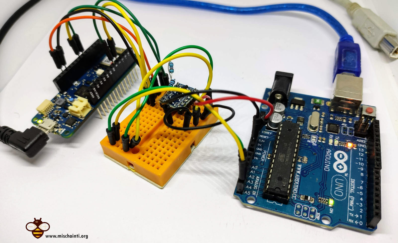
Per la connessione con la stessa logica e tensione, fare riferimento a “i2c Arduino: come creare una rete, parametri e scanner di indirizzi“, qui collegherò tramite l’I2C un Arduino MKR1010 WiFi con un Arduino UNO.
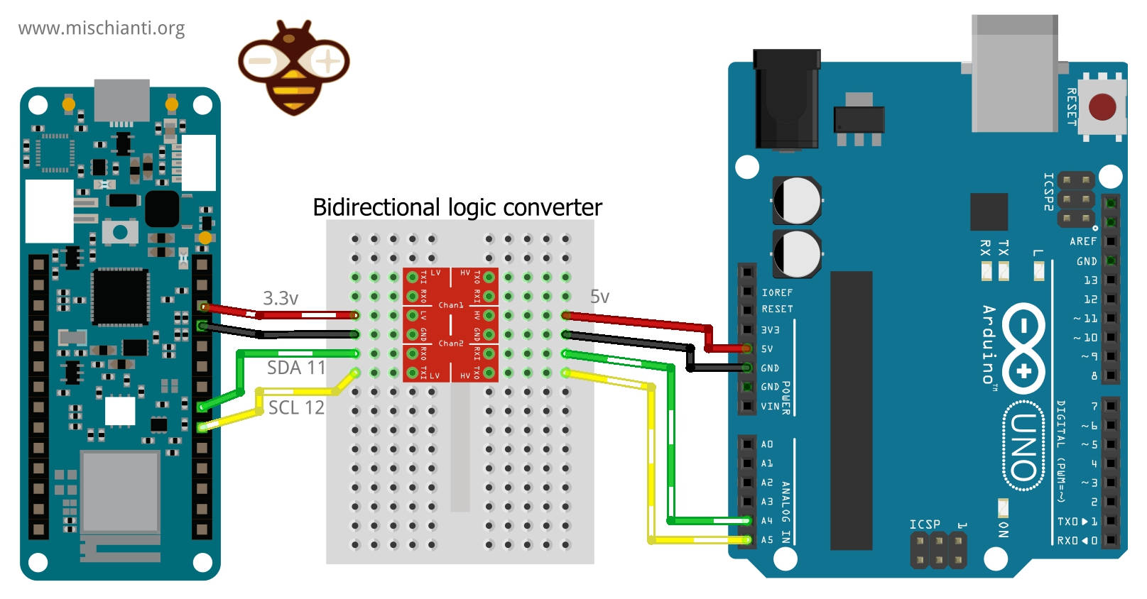
Devi ricordare che Arduino UNO ha una logica 5v, Arduino MKR ha una logica 3.3v e non è tollerante a 5v.
Ecco il convertitore di logica bidirezionale Aliexpress
Qui il set di schede Arduino classiche Arduino UNO - Arduino MEGA 2560 R3 - Arduino Nano - Arduino Pro Mini
Un master e uno slave
La connessione è semplice i 3.3v dell’Arduino MKR devono essere conessi a LV, e sul lato del Low Voltage, tu devi connettere l’SDA 11 al LV1 e SCL 12 al LV2, il 5v dell’Arduino UNO al HV e SDA A4 al HV1 e SCL A5 al HV2.
Il codice per il master è lo stesso spiegato nell’articolo precedente e funziona con entrambi i microcontrollori.
/**
 * i2c network: send parameter to client and receive response
 * with data relative to the request. MASTER SKETCH
 *
 * by Renzo Mischianti <www.mischianti.org>
 *
 * https://mischianti.org
 *
 * Arduino UNO <------> 	Logic converter <------> 	Arduino MKR
 * GND						GND			GND				GND
 * 5v						HV			LV				3.3v
 * A4						HV1			LV1				11
 * A5						HV2			LV2				12
 *
 */

#include <Wire.h>

enum REQUEST_TYPE {
	NONE = -1,
	GET_NAME = 0,
	GET_AGE
};

void setup() {
	Wire.begin();        // join i2c bus (address optional for master)
	Serial.begin(9600);  // start serial for output

	while (!Serial){}

	Wire.beginTransmission(0x10); 	// Start channel with slave 0x10
	Wire.write(GET_NAME);        		// send data to the slave
	Wire.endTransmission();       	// End transmission

    // Now the request

	Wire.requestFrom(0x10, 14);    // request 14 bytes from slave device 0x10

	while (Wire.available()) { // slave may send less than requested
		char c = Wire.read(); // receive a byte as character
		Serial.print(c);         // print the character
	}

	Serial.println();

	delay(1000); // added to get better Serial print

	Wire.beginTransmission(0x10); 	// Start channel with slave 0x10
	Wire.write(GET_AGE);        		// send data to the slave
	Wire.endTransmission();       	// End transmission

    // Now the request

	Wire.requestFrom(0x10, 1);    // request 1 bytes from slave device 0x10

	while (Wire.available()) { // slave may send less than requested
		int c = (int)Wire.read(); // receive a byte as character
		Serial.println(c);         // print the character
	}
}

void loop() {
}
To understand the basic commands of I2C refer to the “I2C Arduino article”.
Anche lo sketch dello slave è lo stesso, cambio solo l’indirizzo in 0x10.
/**
 * i2c network: send parameter to client and receive response
 * with data relative to the request. SLAVE SKETCH 3
 *
 * by Renzo Mischianti <www.mischianti.org>
 *
 * https://mischianti.org
 *
 * Arduino UNO <------> 	Logic converter <------> 	Arduino MKR
 * GND						GND			GND				GND
 * 5v						HV			LV				3.3v
 * A4						HV1			LV1				11
 * A5						HV2			LV2				12
 *
 */

#include <Wire.h>

enum I2C_REQUEST_TYPE {
	NONE = -1,
	GET_NAME = 0,
	GET_AGE
};

void requestEvent();
void receiveEvent(int numBytes);

I2C_REQUEST_TYPE request = NONE;

void setup() {
	Wire.begin(0x10);                // join i2c bus with address 0x10

	Serial.begin(9600);  // start serial for output

	while (!Serial){}

	// event handler initializations
	Wire.onReceive(receiveEvent);    // register an event handler for received data
	Wire.onRequest(requestEvent);   // register an event handler for data requests
}

void loop() {
//  delay(100);
}

// function that executes whenever data is requested by master
// this function is registered as an event, see setup()
void requestEvent() {
	switch (request) {
		case NONE:
			Serial.println(F("Not good, no request type!"));
			break;
		case GET_NAME:
			Wire.write("ArduinoMKR    "); // send 14 bytes to master
			request = NONE;
			break;
		case GET_AGE:
			Wire.write((byte)47); // send 1 bytes to master
			request = NONE;
			break;
		default:
			break;
	}
}

// function that executes whenever data is received by master
// this function is registered as an event, see setup()
void receiveEvent(int numBytes) {
	if (numBytes==1){
		int requestVal = Wire.read();

		Serial.print(F("Received request -> "));
		Serial.println(requestVal);
		request = static_cast<I2C_REQUEST_TYPE>(requestVal);
	}else{
		Serial.print(F("No parameter received!"));
	}
}
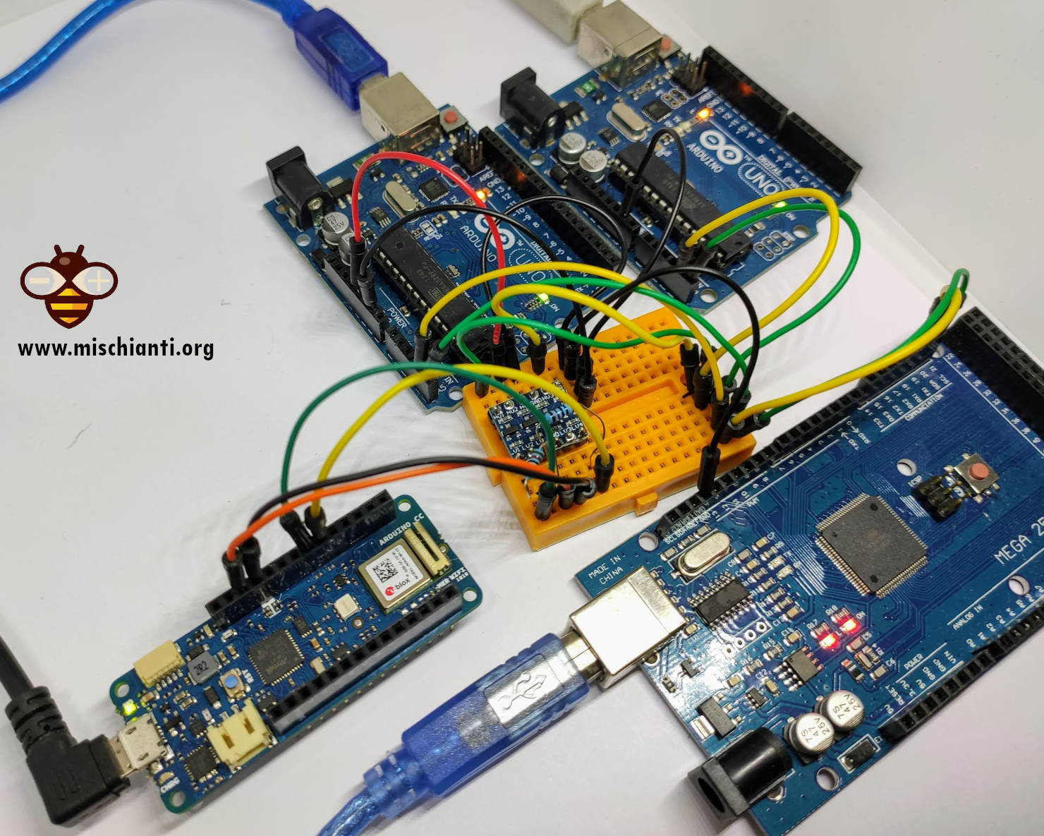
Un master e più slave con passaggio parametro
Ora estenderemo l’esempio “One master multiple slave”, aggiungendo l’Arduino MKR1010 WiFi in questo modo.
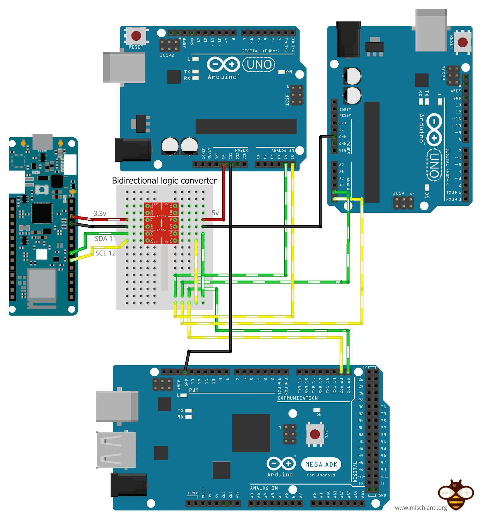
Ora lo sketch del Master con la richiesta al nostro MKR.
/**
 * i2c network: send parameter to client and receive response
 * with data relative to the request
 *
 * by Renzo Mischianti <www.mischianti.org>
 *
 * https://mischianti.org
 *
 * Arduino UNO <------> 	Logic converter <------> 	Arduino MKR
 * GND						GND			GND				GND
 * 5v						HV			LV				3.3v
 * A4						HV1			LV1				11
 * A5						HV2			LV2				12
 *
 */

#include <Wire.h>

enum REQUEST_TYPE {
	NONE = -1,
	GET_NAME = 0,
	GET_AGE
};

void setup() {
	Wire.begin();        // join i2c bus (address optional for master)
	Serial.begin(9600);  // start serial for output

	while (!Serial){}
	Serial.flush();
	Serial.println();

	Wire.beginTransmission(0x08); 	// Start channel with slave 0x08
	Wire.write(GET_NAME);        		// send data to the slave
	Wire.endTransmission();       	// End transmission

	delay(1000); // added to get better Serial print

	Wire.requestFrom(0x08, 14);    // request 14 bytes from slave device 0x08

	while (Wire.available()) { // slave may send less than requested
		char c = Wire.read(); // receive a byte as character
		Serial.print(c);         // print the character
	}

	Serial.println();

	Wire.beginTransmission(0x09); 	// Start channel with slave 0x09
	Wire.write(GET_NAME);        		// send data to the slave
	Wire.endTransmission();       	// End transmission

	delay(1000); // added to get better Serial print

	Wire.requestFrom(0x09, 14);    // request 14 bytes from slave device 0x09

	while (Wire.available()) { // slave may send less than requested
		char c = Wire.read(); // receive a byte as character
		Serial.print(c);         // print the character
	}

	Serial.println();

	Wire.beginTransmission(0x10); 	// Start channel with slave 0x10
	Wire.write(GET_NAME);        		// send data to the slave
	Wire.endTransmission();       	// End transmission

	delay(1000); // added to get better Serial print

	Wire.requestFrom(0x10, 14);    // request 14 bytes from slave device 0x10

	while (Wire.available()) { // slave may send less than requested
		char c = Wire.read(); // receive a byte as character
		Serial.print(c);         // print the character
	}

	Serial.println();

	delay(1000); // added to get better Serial print

	Wire.beginTransmission(0x08); 	// Start channel with slave 0x08
	Wire.write(GET_AGE);        		// send data to the slave
	Wire.endTransmission();       	// End transmission

	delay(1000); // added to get better Serial print

	Wire.requestFrom(0x08, 1);    // request 1 bytes from slave device 0x08

	while (Wire.available()) { // slave may send less than requested
		int c = (int)Wire.read(); // receive a byte as character
		Serial.println(c);         // print the character
	}

	Wire.beginTransmission(0x09); 	// Start channel with slave 0x09
	Wire.write(GET_AGE);        		// send data to the slave
	Wire.endTransmission();       	// End transmission

	delay(1000); // added to get better Serial print

	Wire.requestFrom(0x09, 1);    // request 1 bytes from slave device 0x09

	while (Wire.available()) { // slave may send less than requested
		int c = (int)Wire.read(); // receive a byte as character
		Serial.println(c);         // print the character
	}

	Wire.beginTransmission(0x10); 	// Start channel with slave 0x10
	Wire.write(GET_AGE);        		// send data to the slave
	Wire.endTransmission();       	// End transmission

	delay(1000); // added to get better Serial print

	Wire.requestFrom(0x10, 1);    // request 1 bytes from slave device 0x10

	while (Wire.available()) { // slave may send less than requested
		int c = (int)Wire.read(); // receive a byte as character
		Serial.println(c);         // print the character
	}

}

void loop() {
}
Il risultato del master ora è
ArduinoUNO
ArduinoMEGA
ArduinoMKR
43
45
47
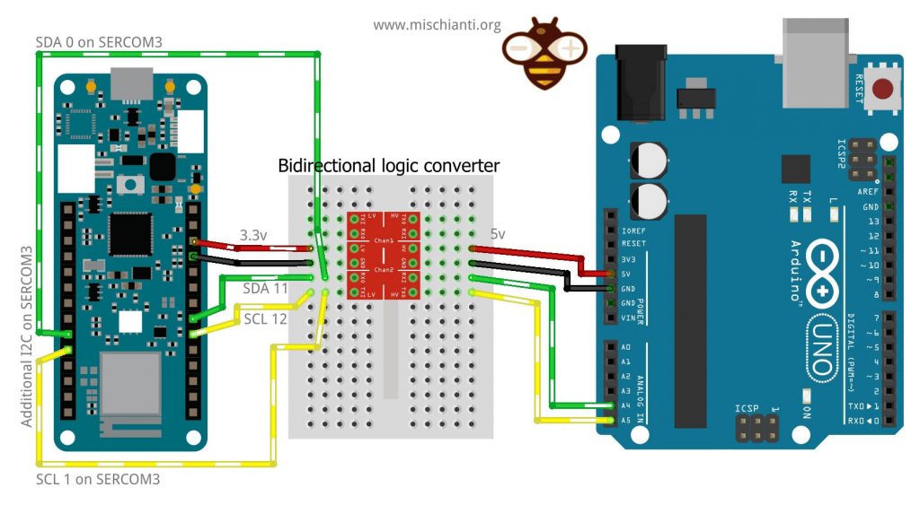
Aggiungi una nuova interfaccia I2C con SERCOM
Come descritto, i dispositivi SAMD dispongono di una serie di interfacce SERCOM che possono essere configurate come UART, SPI o I2C.
Controllare lo schema precedente e selezionare un’interfaccia SERCOM libera; Seleziono SERCOM3 per il mio scopo.
Userò il pin 0 come SDA e il pin 1 come SCL, per assegnare questa interfaccia I2C a SERCOM3 devi prima istanziare l’interfaccia Wire.
TwoWire myWire(&sercom3, 0, 1); // Create the new wire instance assigning it to pin 0 and 1
Quindi è necessario specificare che PIN 0 e PIN 1 sono pin SERCOM.
	myWire.begin(0x11);                // join i2c bus on sercom3 with address 0x11
	pinPeripheral(0, PIO_SERCOM);   //Assign SDA function to pin 0
	pinPeripheral(1, PIO_SERCOM);   //Assign SCL function to pin 1
Ora la cosa più importante è collegare il gestore di interrupt al SERCOM.
// Attach the interrupt handler to the SERCOM
extern "C" {

  void SERCOM3_Handler(void);

  void SERCOM3_Handler(void) {

    myWire.onService();

  }
}
Ora la tua nuova interfaccia I2C è pronta e può essere utilizzata come SLAVE come l’altra, e ho assegnato a questa nuova interfaccia l’indirizzo 0x11.
myWire.begin(0x11); // join i2c bus on sercom3 with address 0x11
E aggiungo aggiungo 2 nuovi callback di eventi di ricezione e richiesta.
	// event handler initializations
	myWire.onReceive(receiveEventSercom);    // register an event handler for received data
	myWire.onRequest(requestEventSercom);   // register an event handler for data requests
Ora devi cablare questa nuova interfaccia I2C.
Se avvii un nuovo scanner di indirizzi I2C, il risultato sul master Serial è questo.
Scanning...
I2C device found at address 0x10  !
I2C device found at address 0x11  !
I2C device found at address 0x60  !
I2C device found at address 0x6B  !
done
Puoi trovare nuovi dispositivi I2C che corrispondono al nostro SERCOM3 I2C.
Ecco lo sketch completo del doppio SLAVE per Arduino MKR 1010 WiFi.
/**
 * i2c network: send parameter to client and receive response
 * with data relative to the request. SLAVE SKETCH 4
 *
 * We are going to create 2 i2c SLAVE on 2 different SERCOM
 * interface, the first with address 0x10 to the standard Wire
 * the second on additional i2c SERCOM3 interface
 *
 * by Renzo Mischianti <www.mischianti.org>
 *
 * https://mischianti.org
 *
 * Arduino UNO <------> 	Logic converter <------> 	Arduino MKR <------> 	Arduino MKR
 * GND						GND			GND				GND
 * 5v						HV			LV				3.3v
 * A4						HV1			LV1				11						1
 * A5						HV2			LV2				12						0
 *
 */

#include <Wire.h>
#include "wiring_private.h"

TwoWire myWire(&sercom3, 0, 1);   // Create the new wire instance assigning it to pin 0 and 1

enum I2C_REQUEST_TYPE {
	NONE = -1,
	GET_NAME = 0,
	GET_AGE
};
void requestEvent();
void receiveEvent(int numBytes);
void requestEventSercom();
void receiveEventSercom(int numBytes);

I2C_REQUEST_TYPE request = NONE;
I2C_REQUEST_TYPE request_sercom = NONE;

void setup() {
	Wire.begin(0x10);                // join i2c bus with address 0x10

	myWire.begin(0x11);                // join i2c bus on sercom3 with address 0x11
	pinPeripheral(0, PIO_SERCOM);   //Assign SDA function to pin 0
	pinPeripheral(1, PIO_SERCOM);   //Assign SCL function to pin 1

	Serial.begin(9600);  // start serial for output

	while (!Serial){}

	// event handler initializations
	Wire.onReceive(receiveEvent);    // register an event handler for received data
	Wire.onRequest(requestEvent);   // register an event handler for data requests
	// event handler initializations
	myWire.onReceive(receiveEventSercom);    // register an event handler for received data
	myWire.onRequest(requestEventSercom);   // register an event handler for data requests
}

void loop() {
	  delay(100);
}

// function that executes whenever data is requested by master
// this function is registered as an event, see setup()
void requestEvent() {
	switch (request) {
		case NONE:
			Serial.println(F("Not good, no request type!"));
			break;
		case GET_NAME:
			Wire.write("ArduinoMKR    "); // send 14 bytes to master
			request = NONE;
			break;
		case GET_AGE:
			Wire.write((byte)47); // send 1 bytes to master
			request = NONE;
			break;
		default:
			break;
	}
}

// function that executes whenever data is received by master
// this function is registered as an event, see setup()
void receiveEvent(int numBytes) {
	if (numBytes==1){
		int requestVal = Wire.read();

		Serial.print(F("Received request -> "));
		Serial.println(requestVal);
		request = static_cast<I2C_REQUEST_TYPE>(requestVal);
	}else{
		Serial.print(F("No parameter received!"));
	}
}

// function that executes whenever data is requested by master
// this function is registered as an event, see setup()
void requestEventSercom() {
	switch (request_sercom) {
		case NONE:
			Serial.println(F("Not good, no request type!"));
			break;
		case GET_NAME:
			myWire.write("ArduinoMKR SER"); // send 14 bytes to master
			request_sercom = NONE;
			break;
		case GET_AGE:
			myWire.write((byte)57); // send 1 bytes to master
			request_sercom = NONE;
			break;
		default:
			break;
	}
}

// function that executes whenever data is received by master
// this function is registered as an event, see setup()
void receiveEventSercom(int numBytes) {
	if (numBytes==1){
		int requestVal = myWire.read();

		Serial.print(F("Received request on SERCOM3 -> "));
		Serial.println(requestVal);
		request_sercom = static_cast<I2C_REQUEST_TYPE>(requestVal);
	}else{
		Serial.print(F("No parameter received!"));
	}
}

// Attach the interrupt handler to the SERCOM
extern "C" {

  void SERCOM3_Handler(void);

  void SERCOM3_Handler(void) {

    myWire.onService();

  }
}
Ora, se abbiamo intenzione di cambiare lo sketch del master per chiedere informazioni anche a questa nuova interfaccia, ecco lo sketch principale per questo scopo.
/**
 * i2c network: send parameter to client and receive response
 * with data relative to the request
 *
 * by Renzo Mischianti <www.mischianti.org>
 *
 * https://mischianti.org
 *
 * Arduino UNO <------> Arduino UNO
 * GND					GND
 * A4					A4
 * A5					A5
 *
 */

#include <Wire.h>

enum REQUEST_TYPE {
	NONE = -1,
	GET_NAME = 0,
	GET_AGE
};

void setup() {
	Wire.begin();        // join i2c bus (address optional for master)
	Serial.begin(9600);  // start serial for output

	while (!Serial){}
	Serial.flush();
	Serial.println();

	Wire.beginTransmission(0x10); 	// Start channel with slave 0x10
	Wire.write(GET_NAME);        		// send data to the slave
	Wire.endTransmission();       	// End transmission

	delay(1000); // added to get better Serial print

	Wire.requestFrom(0x10, 14);    // request 14 bytes from slave device 0x10

	while (Wire.available()) { // slave may send less than requested
		char c = Wire.read(); // receive a byte as character
		Serial.print(c);         // print the character
	}

	Serial.println();

	Wire.beginTransmission(0x11); 	// Start channel with slave 0x11
	Wire.write(GET_NAME);        		// send data to the slave
	Wire.endTransmission();       	// End transmission

	delay(1000); // added to get better Serial print

	Wire.requestFrom(0x11, 14);    // request 14 bytes from slave device 0x11

	while (Wire.available()) { // slave may send less than requested
		char c = Wire.read(); // receive a byte as character
		Serial.print(c);         // print the character
	}

	Serial.println();

	delay(1000); // added to get better Serial print

	Wire.beginTransmission(0x10); 	// Start channel with slave 0x10
	Wire.write(GET_AGE);        		// send data to the slave
	Wire.endTransmission();       	// End transmission

	delay(1000); // added to get better Serial print

	Wire.requestFrom(0x10, 1);    // request 1 bytes from slave device 0x10

	while (Wire.available()) { // slave may send less than requested
		int c = (int)Wire.read(); // receive a byte as character
		Serial.println(c);         // print the character
	}

	Wire.beginTransmission(0x11); 	// Start channel with slave 0x11
	Wire.write(GET_AGE);        		// send data to the slave
	Wire.endTransmission();       	// End transmission

	delay(1000); // added to get better Serial print

	Wire.requestFrom(0x11, 1);    // request 1 bytes from slave device 0x11

	while (Wire.available()) { // slave may send less than requested
		int c = (int)Wire.read(); // receive a byte as character
		Serial.println(c);         // print the character
	}
}

void loop() {
}
Ed ecco l’output seriale dello sketch principale:
ArduinoMKR
ArduinoMKR SER
47
57
Come puoi vedere, le 2 interfacce i2c sono canali indipendenti e lo stesso microcontrollore risulta in più slave I2C.
Thanks
- Arduino SAMD NINA: piedinatura, specifiche e configurazione Arduino IDE
- Arduino SAMD NINA: WiFiNINA, aggiornamento firmware e led RGB
- Arduino SAMD (NANO 33 e MKR): file system FAT su memoria flash SPI esterna
- i2c Arduino SAMD MKR: interfaccia aggiuntiva SERCOM, rete e scanner di indirizzi
- Arduino MKR SAMD: file system FAT su memoria flash SPI esterna
- Collegamento dell’EByte E70 ai dispositivi Arduino SAMD (Nano 33, MKR…) e un semplice sketch di esempio
- i2c Arduino: how to create a network, parameters, and address scanner
- i2c Arduino SAMD MKR: additional interface SERCOM, network, and address scanner
- i2c esp8266: how to, network 5v, 3.3v, speed, and address scanner