ESP32-2432S028 (Cheap Yellow Display): piedinatura ad alta risoluzione, scheda dati, schema e specifiche
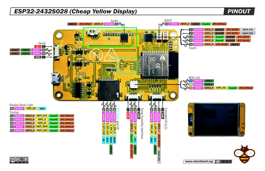
L’ESP32-2432S028, meglio conosciuto dai maker come il Cheap Yellow Display (CYD), è una scheda di sviluppo ESP32 all-in-one con un pannello touch resistivo TFT da 2,8 pollici 240 × 320 px, micro-SD, connettore per altoparlante, LED di stato RGB, sensore di luce e bridge da USB a UART. Costa circa 15 USD e viene spedito completamente assemblato: una piattaforma GUI istantanea per dashboard IoT, datalogger o pannelli per la casa intelligente.
Ecco la mia selezione di ESP32 ESP32 Dev Kit v1 - TTGO T-Display 1.14 ESP32 - NodeMCU V3 V2 ESP8266 Lolin32 - NodeMCU ESP-32S - WeMos Lolin32 - WeMos Lolin32 mini - ESP32-CAM programmer - ESP32-CAM bundle - ESP32-WROOM-32 - ESP32-S - ESP32-WROOM-32 - ESP32 2.8 Inch Touch ESP32-2432S028
Ecco la mia selezione di TFT 240 * 320 ILI9341 2,8 - from 320 * 240 ILI9341 from 2,2 to 3,5 - TFT Round 240 * 240 GC9A01 1,28" - CrowPanel ESP32-C3 240*240 Round IPS Display Capacitive Touch 1,28" - Aliexpress CrowPanel ESP32-C3 240*240 Round IPS Display Capacitive Touch 1,28"- ESP32 2.8 Inch Touch ESP32-2432S028
Specifiche principali
| Categoria | Dettagli |
|---|---|
| MCU | ESP32-WROOM-32 (dual-core Xtensa LX6 @ 240 MHz, Wi-Fi b/g/n + BT v4.2) |
| Flash / RAM | 4 MB QSPI flash, 520 KB SRAM |
| Schermo | TFT da 2,8″ 240 × 320 (ILI9341), 65k colori, retroilluminazione su GPIO 21 |
| Tocco | Controller resistivo XPT2046 su bus VSPI |
| Audio | Amplificatore in classe D PAM8002A da 3 W, GPIO 26 |
| Archiviazione | micro-SD (fino a 32 GB) su VSPI |
| I/O integrato | LED RGB (GPIO 4/16/17, attivo-BASSO), LDR (GPIO 34) |
| Pulsanti utente | BOOT (GPIO 0), RESET (pin EN) |
| GPIO liberi | 35 (solo ingresso), 22, 27 su connettori JST |
| Ingresso alimentazione | 5 V tramite micro-USB, doppi LDO AMS1117 a 3,3 V |
| Assorbimento tipico | ≈ 115 mA con retroilluminazione a piena luminosità |
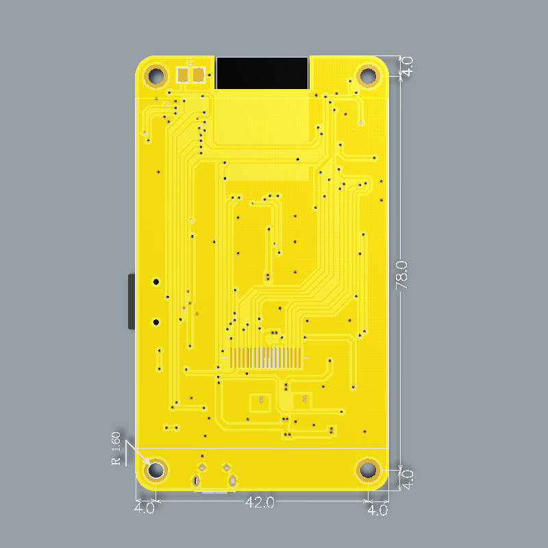
| Dimensioni / Peso | 86 × 50 mm, ~50 g |
Mappa funzionale
| Blocco | Interfaccia | Pin ESP32 | Note |
|---|---|---|---|
| LCD (HSPI) | SPI | 12 (MISO), 13 (MOSI), 14 (SCK), 15 (CS), 2 (DC) | RST collegato a HIGH |
| Touch (VSPI) | SPI | 39 (MISO), 32 (MOSI), 25 (SCK), 33 (CS), 36 (IRQ) | |
| micro-SD (VSPI) | SPI | 19 (MISO), 23 (MOSI), 18 (SCK), 5 (CS) | VSPI condiviso |
| Audio out | DAC/PWM | 26 | JST a 2 pin |
| RGB LED | GPIO | 4 (R), 16 (G), 17 (B) | attivo-BASSO |
| LDR | ADC | 34 | ADC1 a 10 bit |
| Connettori esposti | JST-P1 (UART), P3, CN1 |
Piedinatura in breve
| Connettore | Piedinatura | Uso tipico |
|---|---|---|
| P1 (UART) | VIN – TX (1) – RX (3) – GND | Lampeggio del firmware / console seriale |
| P3 | GND – 35 (IN) – 22 – 21 (BL) | GPIO extra; evitare il 21 se è necessaria la retroilluminazione |
| CN1 | GND – 22 – 27 – 3V3 | Connettore I²C ideale (22 =SCL, 27 =SDA) |
| P4 | 26 – GND | Altoparlante |
| Buttons | BOOT (0), RESET (EN) | Controllo flash e ripristino |
Riepilogo GPIO disponibili: 22, 27, 35 (solo IN)—tutti gli altri sono permanentemente cablati a display, touch, SD, LED o audio.
Considerazioni sull’alimentazione
La scheda è concepita solo per USB a 5 V; i doppi regolatori AMS1117 isolano l’ESP32 e il display per ridurre al minimo il rumore. Con la retroilluminazione al 100%, i picchi di corrente si attestano intorno a 115 mA; l’oscuramento di GPIO 21 tramite PWM riduce l’assorbimento di circa il 40%. Le modalità di sospensione scendono al di sotto di 8 mA, ma è necessario spegnere anche la retroilluminazione e l’amplificatore per raggiungere i valori di sonno profondo.
Opzioni di sviluppo
| Ambiente | Punti salienti |
|---|---|
| Arduino IDE / PlatformIO | Scheda: ESP32 Dev Module; baud 921 600; installare il driver CH340. Copia TFT_eSPI/User_Setup_CYD.h dal repository per la mappatura corretta dei pin. |
| ESP-IDF | Funziona immediatamente; utilizzare esp_lcd_panel_io_spi per ILI9341, esp_lcd_touch_xpt2046 per il tocco. |
| MicroPython | Flash l’ultima build, quindi gli esempi di micropython-touch-lcd. |
| CircuitPython | Immagini UF2 pre-compilate disponibili dall’indice delle schede Adafruit. |
| LVGL | Framework GUI completo; compilare con LV_COLOR_16_SWAP=1 e disp_driver=ili9341. |
| TFT_eSPI / LovyanGFX / Arduino_GFX | Librerie di visualizzazione alternative ad alte prestazioni. |
Pro e contro
| ✅ Pro | ⚠️ Contro |
|---|---|
| Tutto su un unico PCB: display, touch, SD, audio, USB | Solo 3 GPIO liberi |
| Costo estremamente basso | Tocco resistivo (senza multitouch) |
| Ottima documentazione ed esempi della community | Solo ingresso a 5 V |
| Perfetto per la prototipazione rapida di GUI | Nessun limite di corrente hardware per l’altoparlante |
How to
- ESP32: piedinatura, specifiche e configurazione dell’Arduino IDE
- ESP32: fileSystem integrato SPIFFS
- ESP32: gestire più seriali e logging per il debug
- ESP32 risparmio energetico pratico
- ESP32 risparmio energetico pratico: gestire WiFi e CPU
- ESP32 risparmio energetico pratico: modem e light sleep
- ESP32 risparmio energetico pratico: deep sleep e ibernazione
- ESP32 risparmio energetico pratico: preservare dati al riavvio, sveglia a tempo e tramite tocco
- ESP32 risparmio energetico pratico: sveglia esterna e da ULP
- ESP32 risparmio energetico pratico: sveglia da UART e GPIO
- ESP32: filesystem integrato LittleFS
- ESP32: filesystem integrato FFat (Fat/exFAT)
- ESP32-wroom-32
- ESP32-CAM
- ESP32: ethernet w5500 con chiamate standard (HTTP) e SSL (HTTPS)
- ESP32: ethernet enc28j60 con chiamate standard (HTTP) e SSL (HTTPS)
- Come usare la scheda SD con l’esp32
- esp32 e esp8266: file system FAT su memoria SPI flash esterna
- Gestione aggiornamenti firmware e OTA
- Gestione del firmware
- Aggiornamento OTA con Arduino IDE
- Aggiornamento OTA con browser web
- Aggiornamenti automatici OTA da un server HTTP
- Aggiornamento del firmware non standard
- Integrare LAN8720 con ESP32 per la connettività Ethernet con plain (HTTP) e SSL (HTTPS)
- Collegare l’EByte E70 (CC1310) ai dispositivi ESP32 c3/s3 ed un semplice sketch di esempio
- ESP32-C3: piedinatura, specifiche e configurazione dell’IDE Arduino
- Integrazione del modulo W5500 su ESP32 con Core 3: supporto nativo ai protocolli Ethernet con SSL e altre funzionalità
- Integrazione del modulo LAN8720 su ESP32 con Core 3: supporto nativo del protocollo Ethernet con SSL e altre funzionalità.
- Dallas DS18B20
- Guida all’I2C su ESP32: comunicazione con dispositivi eterogenei 5v 3.3v, gestione interfacce aggiuntive
- Display
- Guida Completa: Come Usare un Display ILI9341 con la Libreria TFT_eSPI
- Come integrare la funzionalità touch screen nel display TFT ILI9341
- Display eInk SSD1683 con GxEPD e ESP32 (e HMI CrowPanel 4,2″): nozioni di base e configurazione
- Display e-ink SSD1683 con GxEPD e ESP32 (e CrowPanel 4.2″ HMI): font, forme e immagini
Datasheet
Schema della scheda
Specifiche
Dimensioni PCB
TFT_eSPI User_data.h
//                            USER DEFINED SETTINGS
//   Set driver type, fonts to be loaded, pins used and SPI control method etc
//
//   See the User_Setup_Select.h file if you wish to be able to define multiple
//   setups and then easily select which setup file is used by the compiler.
//
//   If this file is edited correctly then all the library example sketches should
//   run without the need to make any more changes for a particular hardware setup!
//   Note that some sketches are designed for a particular TFT pixel width/height
// by Renzo Mischianti <mischianti.org>
// User defined information reported by "Read_User_Setup" test & diagnostics example
#define USER_SETUP_INFO "User_Setup"

// Define to disable all #warnings in library (can be put in User_Setup_Select.h)
//#define DISABLE_ALL_LIBRARY_WARNINGS

// ##################################################################################
//
// Section 1. Call up the right driver file and any options for it
//
// ##################################################################################

// Define STM32 to invoke optimised processor support (only for STM32)
//#define STM32

// Defining the STM32 board allows the library to optimise the performance
// for UNO compatible "MCUfriend" style shields
//#define NUCLEO_64_TFT
//#define NUCLEO_144_TFT

// STM32 8 bit parallel only:
// If STN32 Port A or B pins 0-7 are used for 8 bit parallel data bus bits 0-7
// then this will improve rendering performance by a factor of ~8x
//#define STM_PORTA_DATA_BUS
//#define STM_PORTB_DATA_BUS

// Tell the library to use parallel mode (otherwise SPI is assumed)
//#define TFT_PARALLEL_8_BIT
//#defined TFT_PARALLEL_16_BIT // **** 16 bit parallel ONLY for RP2040 processor ****

// Display type -  only define if RPi display
//#define RPI_DISPLAY_TYPE // 20MHz maximum SPI

// Only define one driver, the other ones must be commented out
//#define ILI9341_DRIVER       // Generic driver for common displays
#define ILI9341_2_DRIVER     // Alternative ILI9341 driver, see https://github.com/Bodmer/TFT_eSPI/issues/1172
//#define ST7735_DRIVER      // Define additional parameters below for this display
//#define ILI9163_DRIVER     // Define additional parameters below for this display
//#define S6D02A1_DRIVER
//#define RPI_ILI9486_DRIVER // 20MHz maximum SPI
//#define HX8357D_DRIVER
//#define ILI9481_DRIVER
//#define ILI9486_DRIVER
//#define ILI9488_DRIVER     // WARNING: Do not connect ILI9488 display SDO to MISO if other devices share the SPI bus (TFT SDO does NOT tristate when CS is high)
//#define ST7789_DRIVER      // Full configuration option, define additional parameters below for this display
//#define ST7789_2_DRIVER    // Minimal configuration option, define additional parameters below for this display
//#define R61581_DRIVER
//#define RM68140_DRIVER
//#define ST7796_DRIVER
//#define SSD1351_DRIVER
//#define SSD1963_480_DRIVER
//#define SSD1963_800_DRIVER
//#define SSD1963_800ALT_DRIVER
//#define ILI9225_DRIVER
//#define GC9A01_DRIVER

// Some displays support SPI reads via the MISO pin, other displays have a single
// bi-directional SDA pin and the library will try to read this via the MOSI line.
// To use the SDA line for reading data from the TFT uncomment the following line:

// #define TFT_SDA_READ      // This option is for ESP32 ONLY, tested with ST7789 and GC9A01 display only

// For ST7735, ST7789 and ILI9341 ONLY, define the colour order IF the blue and red are swapped on your display
// Try ONE option at a time to find the correct colour order for your display

//  #define TFT_RGB_ORDER TFT_RGB  // Colour order Red-Green-Blue
//  #define TFT_RGB_ORDER TFT_BGR  // Colour order Blue-Green-Red

// For M5Stack ESP32 module with integrated ILI9341 display ONLY, remove // in line below

// #define M5STACK

// For ST7789, ST7735, ILI9163 and GC9A01 ONLY, define the pixel width and height in portrait orientation
// #define TFT_WIDTH  80
// #define TFT_WIDTH  128
// #define TFT_WIDTH  172 // ST7789 172 x 320
#define TFT_WIDTH  240 // ST7789 240 x 240 and 240 x 320
// #define TFT_HEIGHT 160
// #define TFT_HEIGHT 128
// #define TFT_HEIGHT 240 // ST7789 240 x 240
#define TFT_HEIGHT 320 // ST7789 240 x 320
// #define TFT_HEIGHT 240 // GC9A01 240 x 240

// For ST7735 ONLY, define the type of display, originally this was based on the
// colour of the tab on the screen protector film but this is not always true, so try
// out the different options below if the screen does not display graphics correctly,
// e.g. colours wrong, mirror images, or stray pixels at the edges.
// Comment out ALL BUT ONE of these options for a ST7735 display driver, save this
// this User_Setup file, then rebuild and upload the sketch to the board again:

// #define ST7735_INITB
// #define ST7735_GREENTAB
// #define ST7735_GREENTAB2
// #define ST7735_GREENTAB3
// #define ST7735_GREENTAB128    // For 128 x 128 display
// #define ST7735_GREENTAB160x80 // For 160 x 80 display (BGR, inverted, 26 offset)
// #define ST7735_ROBOTLCD       // For some RobotLCD arduino shields (128x160, BGR, https://docs.arduino.cc/retired/getting-started-guides/TFT)
// #define ST7735_REDTAB
// #define ST7735_BLACKTAB
// #define ST7735_REDTAB160x80   // For 160 x 80 display with 24 pixel offset

// If colours are inverted (white shows as black) then uncomment one of the next
// 2 lines try both options, one of the options should correct the inversion.

// #define TFT_INVERSION_ON
// #define TFT_INVERSION_OFF


// ##################################################################################
//
// Section 2. Define the pins that are used to interface with the display here
//
// ##################################################################################

// If a backlight control signal is available then define the TFT_BL pin in Section 2
// below. The backlight will be turned ON when tft.begin() is called, but the library
// needs to know if the LEDs are ON with the pin HIGH or LOW. If the LEDs are to be
// driven with a PWM signal or turned OFF/ON then this must be handled by the user
// sketch. e.g. with digitalWrite(TFT_BL, LOW);

#define TFT_BL   21            // LED back-light control pin
#define TFT_BACKLIGHT_ON HIGH  // Level to turn ON back-light (HIGH or LOW)


// We must use hardware SPI, a minimum of 3 GPIO pins is needed.
// Typical setup for ESP8266 NodeMCU ESP-12 is :
//
// Display SDO/MISO  to NodeMCU pin D6 (or leave disconnected if not reading TFT)
// Display LED       to NodeMCU pin VIN (or 5V, see below)
// Display SCK       to NodeMCU pin D5
// Display SDI/MOSI  to NodeMCU pin D7
// Display DC (RS/AO)to NodeMCU pin D3
// Display RESET     to NodeMCU pin D4 (or RST, see below)
// Display CS        to NodeMCU pin D8 (or GND, see below)
// Display GND       to NodeMCU pin GND (0V)
// Display VCC       to NodeMCU 5V or 3.3V
//
// The TFT RESET pin can be connected to the NodeMCU RST pin or 3.3V to free up a control pin
//
// The DC (Data Command) pin may be labelled AO or RS (Register Select)
//
// With some displays such as the ILI9341 the TFT CS pin can be connected to GND if no more
// SPI devices (e.g. an SD Card) are connected, in this case comment out the #define TFT_CS
// line below so it is NOT defined. Other displays such at the ST7735 require the TFT CS pin
// to be toggled during setup, so in these cases the TFT_CS line must be defined and connected.
//
// The NodeMCU D0 pin can be used for RST
//
//
// Note: only some versions of the NodeMCU provide the USB 5V on the VIN pin
// If 5V is not available at a pin you can use 3.3V but backlight brightness
// will be lower.


// ###### EDIT THE PIN NUMBERS IN THE LINES FOLLOWING TO SUIT YOUR ESP8266 SETUP ######

// For NodeMCU - use pin numbers in the form PIN_Dx where Dx is the NodeMCU pin designation
//#define TFT_CS   PIN_D8  // Chip select control pin D8
//#define TFT_DC   PIN_D3  // Data Command control pin
//#define TFT_RST  PIN_D4  // Reset pin (could connect to NodeMCU RST, see next line)
//#define TFT_RST  -1    // Set TFT_RST to -1 if the display RESET is connected to NodeMCU RST or 3.3V

//#define TFT_BL PIN_D1  // LED back-light (only for ST7789 with backlight control pin)

//#define TOUCH_CS PIN_D2     // Chip select pin (T_CS) of touch screen

//#define TFT_WR PIN_D2       // Write strobe for modified Raspberry Pi TFT only


// ######  FOR ESP8266 OVERLAP MODE EDIT THE PIN NUMBERS IN THE FOLLOWING LINES  ######

// Overlap mode shares the ESP8266 FLASH SPI bus with the TFT so has a performance impact
// but saves pins for other functions. It is best not to connect MISO as some displays
// do not tristate that line when chip select is high!
// Note: Only one SPI device can share the FLASH SPI lines, so a SPI touch controller
// cannot be connected as well to the same SPI signals.
// On NodeMCU 1.0 SD0=MISO, SD1=MOSI, CLK=SCLK to connect to TFT in overlap mode
// On NodeMCU V3  S0 =MISO, S1 =MOSI, S2 =SCLK
// In ESP8266 overlap mode the following must be defined

//#define TFT_SPI_OVERLAP

// In ESP8266 overlap mode the TFT chip select MUST connect to pin D3
//#define TFT_CS   PIN_D3
//#define TFT_DC   PIN_D5  // Data Command control pin
//#define TFT_RST  PIN_D4  // Reset pin (could connect to NodeMCU RST, see next line)
//#define TFT_RST  -1  // Set TFT_RST to -1 if the display RESET is connected to NodeMCU RST or 3.3V


// ###### EDIT THE PIN NUMBERS IN THE LINES FOLLOWING TO SUIT YOUR ESP32 SETUP   ######

// For ESP32 Dev board (only tested with ILI9341 display)
// The hardware SPI can be mapped to any pins

#define TFT_MISO 12
#define TFT_MOSI 13
#define TFT_SCLK 14
#define TFT_CS   15  // Chip select control pin
#define TFT_DC    2  // Data Command control pin
//#define TFT_RST   4  // Reset pin (could connect to RST pin)
#define TFT_RST  -1  // Set TFT_RST to -1 if display RESET is connected to ESP32 board RST

#define TOUCH_CS 33     // Chip select pin (T_CS) of touch screen

// For ESP32 Dev board (only tested with GC9A01 display)
// The hardware SPI can be mapped to any pins

//#define TFT_MOSI 15 // In some display driver board, it might be written as "SDA" and so on.
//#define TFT_SCLK 14
//#define TFT_CS   5  // Chip select control pin
//#define TFT_DC   27  // Data Command control pin
//#define TFT_RST  33  // Reset pin (could connect to Arduino RESET pin)
//#define TFT_BL   22  // LED back-light

//#define TOUCH_CS 21     // Chip select pin (T_CS) of touch screen

//#define TFT_WR 22    // Write strobe for modified Raspberry Pi TFT only

// For the M5Stack module use these #define lines
//#define TFT_MISO 19
//#define TFT_MOSI 23
//#define TFT_SCLK 18
//#define TFT_CS   14  // Chip select control pin
//#define TFT_DC   27  // Data Command control pin
//#define TFT_RST  33  // Reset pin (could connect to Arduino RESET pin)
//#define TFT_BL   32  // LED back-light (required for M5Stack)

// ######       EDIT THE PINs BELOW TO SUIT YOUR ESP32 PARALLEL TFT SETUP        ######

// The library supports 8 bit parallel TFTs with the ESP32, the pin
// selection below is compatible with ESP32 boards in UNO format.
// Wemos D32 boards need to be modified, see diagram in Tools folder.
// Only ILI9481 and ILI9341 based displays have been tested!

// Parallel bus is only supported for the STM32 and ESP32
// Example below is for ESP32 Parallel interface with UNO displays

// Tell the library to use 8 bit parallel mode (otherwise SPI is assumed)
//#define TFT_PARALLEL_8_BIT

// The ESP32 and TFT the pins used for testing are:
//#define TFT_CS   33  // Chip select control pin (library pulls permanently low
//#define TFT_DC   15  // Data Command control pin - must use a pin in the range 0-31
//#define TFT_RST  32  // Reset pin, toggles on startup

//#define TFT_WR    4  // Write strobe control pin - must use a pin in the range 0-31
//#define TFT_RD    2  // Read strobe control pin

//#define TFT_D0   12  // Must use pins in the range 0-31 for the data bus
//#define TFT_D1   13  // so a single register write sets/clears all bits.
//#define TFT_D2   26  // Pins can be randomly assigned, this does not affect
//#define TFT_D3   25  // TFT screen update performance.
//#define TFT_D4   17
//#define TFT_D5   16
//#define TFT_D6   27
//#define TFT_D7   14

// ######       EDIT THE PINs BELOW TO SUIT YOUR STM32 SPI TFT SETUP        ######

// The TFT can be connected to SPI port 1 or 2
//#define TFT_SPI_PORT 1 // SPI port 1 maximum clock rate is 55MHz
//#define TFT_MOSI PA7
//#define TFT_MISO PA6
//#define TFT_SCLK PA5

//#define TFT_SPI_PORT 2 // SPI port 2 maximum clock rate is 27MHz
//#define TFT_MOSI PB15
//#define TFT_MISO PB14
//#define TFT_SCLK PB13

// Can use Ardiuno pin references, arbitrary allocation, TFT_eSPI controls chip select
//#define TFT_CS   D5 // Chip select control pin to TFT CS
//#define TFT_DC   D6 // Data Command control pin to TFT DC (may be labelled RS = Register Select)
//#define TFT_RST  D7 // Reset pin to TFT RST (or RESET)
// OR alternatively, we can use STM32 port reference names PXnn
//#define TFT_CS   PE11 // Nucleo-F767ZI equivalent of D5
//#define TFT_DC   PE9  // Nucleo-F767ZI equivalent of D6
//#define TFT_RST  PF13 // Nucleo-F767ZI equivalent of D7

//#define TFT_RST  -1   // Set TFT_RST to -1 if the display RESET is connected to processor reset
                        // Use an Arduino pin for initial testing as connecting to processor reset
                        // may not work (pulse too short at power up?)

// ##################################################################################
//
// Section 3. Define the fonts that are to be used here
//
// ##################################################################################

// Comment out the #defines below with // to stop that font being loaded
// The ESP8366 and ESP32 have plenty of memory so commenting out fonts is not
// normally necessary. If all fonts are loaded the extra FLASH space required is
// about 17Kbytes. To save FLASH space only enable the fonts you need!

#define LOAD_GLCD   // Font 1. Original Adafruit 8 pixel font needs ~1820 bytes in FLASH
#define LOAD_FONT2  // Font 2. Small 16 pixel high font, needs ~3534 bytes in FLASH, 96 characters
#define LOAD_FONT4  // Font 4. Medium 26 pixel high font, needs ~5848 bytes in FLASH, 96 characters
#define LOAD_FONT6  // Font 6. Large 48 pixel font, needs ~2666 bytes in FLASH, only characters 1234567890:-.apm
#define LOAD_FONT7  // Font 7. 7 segment 48 pixel font, needs ~2438 bytes in FLASH, only characters 1234567890:-.
#define LOAD_FONT8  // Font 8. Large 75 pixel font needs ~3256 bytes in FLASH, only characters 1234567890:-.
//#define LOAD_FONT8N // Font 8. Alternative to Font 8 above, slightly narrower, so 3 digits fit a 160 pixel TFT
#define LOAD_GFXFF  // FreeFonts. Include access to the 48 Adafruit_GFX free fonts FF1 to FF48 and custom fonts

// Comment out the #define below to stop the SPIFFS filing system and smooth font code being loaded
// this will save ~20kbytes of FLASH
#define SMOOTH_FONT


// ##################################################################################
//
// Section 4. Other options
//
// ##################################################################################

// For RP2040 processor and SPI displays, uncomment the following line to use the PIO interface.
//#define RP2040_PIO_SPI // Leave commented out to use standard RP2040 SPI port interface

// For RP2040 processor and 8 or 16 bit parallel displays:
// The parallel interface write cycle period is derived from a division of the CPU clock
// speed so scales with the processor clock. This means that the divider ratio may need
// to be increased when overclocking. I may also need to be adjusted dependant on the
// display controller type (ILI94341, HX8357C etc). If RP2040_PIO_CLK_DIV is not defined
// the library will set default values which may not suit your display.
// The display controller data sheet will specify the minimum write cycle period. The
// controllers often work reliably for shorter periods, however if the period is too short
// the display may not initialise or graphics will become corrupted.
// PIO write cycle frequency = (CPU clock/(4 * RP2040_PIO_CLK_DIV))
//#define RP2040_PIO_CLK_DIV 1 // 32ns write cycle at 125MHz CPU clock
//#define RP2040_PIO_CLK_DIV 2 // 64ns write cycle at 125MHz CPU clock
//#define RP2040_PIO_CLK_DIV 3 // 96ns write cycle at 125MHz CPU clock

// For the RP2040 processor define the SPI port channel used (default 0 if undefined)
//#define TFT_SPI_PORT 1 // Set to 0 if SPI0 pins are used, or 1 if spi1 pins used

// For the STM32 processor define the SPI port channel used (default 1 if undefined)
//#define TFT_SPI_PORT 2 // Set to 1 for SPI port 1, or 2 for SPI port 2

// Define the SPI clock frequency, this affects the graphics rendering speed. Too
// fast and the TFT driver will not keep up and display corruption appears.
// With an ILI9341 display 40MHz works OK, 80MHz sometimes fails
// With a ST7735 display more than 27MHz may not work (spurious pixels and lines)
// With an ILI9163 display 27 MHz works OK.

// #define SPI_FREQUENCY   1000000
// #define SPI_FREQUENCY   5000000
// #define SPI_FREQUENCY  10000000
// #define SPI_FREQUENCY  20000000
//#define SPI_FREQUENCY  27000000
// #define SPI_FREQUENCY  40000000
#define SPI_FREQUENCY  55000000 // STM32 SPI1 only (SPI2 maximum is 27MHz)
// #define SPI_FREQUENCY  80000000

// Optional reduced SPI frequency for reading TFT
#define SPI_READ_FREQUENCY  20000000

// The XPT2046 requires a lower SPI clock rate of 2.5MHz so we define that here:
#define SPI_TOUCH_FREQUENCY  2500000

// The ESP32 has 2 free SPI ports i.e. VSPI and HSPI, the VSPI is the default.
// If the VSPI port is in use and pins are not accessible (e.g. TTGO T-Beam)
// then uncomment the following line:
#define USE_HSPI_PORT

// Comment out the following #define if "SPI Transactions" do not need to be
// supported. When commented out the code size will be smaller and sketches will
// run slightly faster, so leave it commented out unless you need it!

// Transaction support is needed to work with SD library but not needed with TFT_SdFat
// Transaction support is required if other SPI devices are connected.

// Transactions are automatically enabled by the library for an ESP32 (to use HAL mutex)
// so changing it here has no effect

// #define SUPPORT_TRANSACTIONS
Grazie
- Arduino
- esp8285
- esp8266
- esp12 E
- esp07
- NodeMCU v2.x
- NodeMCU v3.x
- ESP-01
- ESP-01S
- ESP32
- DOIT ESP32 DEV KIT v1
- ESP32 DevKitC v4
- ESP32 WeMos LOLIN32
- ESP32 WeMos LOLIN32 Lite
- ESP32 WeMos LOLIN D32
- ESP32-wroom-32
- NodeMCU-32S
- ESP32-S
- ESP32-CAM
- ESP32-2432S028 (Cheap Yellow Display)
- ESP32-2432S032 (Cheap Yellow Display)
- ESP32c3
- ESP32 c6
- ESP32 s2
- ESP32s3
- Arduino SAMD
- STM32
- Raspberry Pi