ABB Aurora Web Inverter Monitor (WIM): wiring and PCB soldering – 8
Now the hardware, I have created a PCB for this project, it is quite simple to assemble .
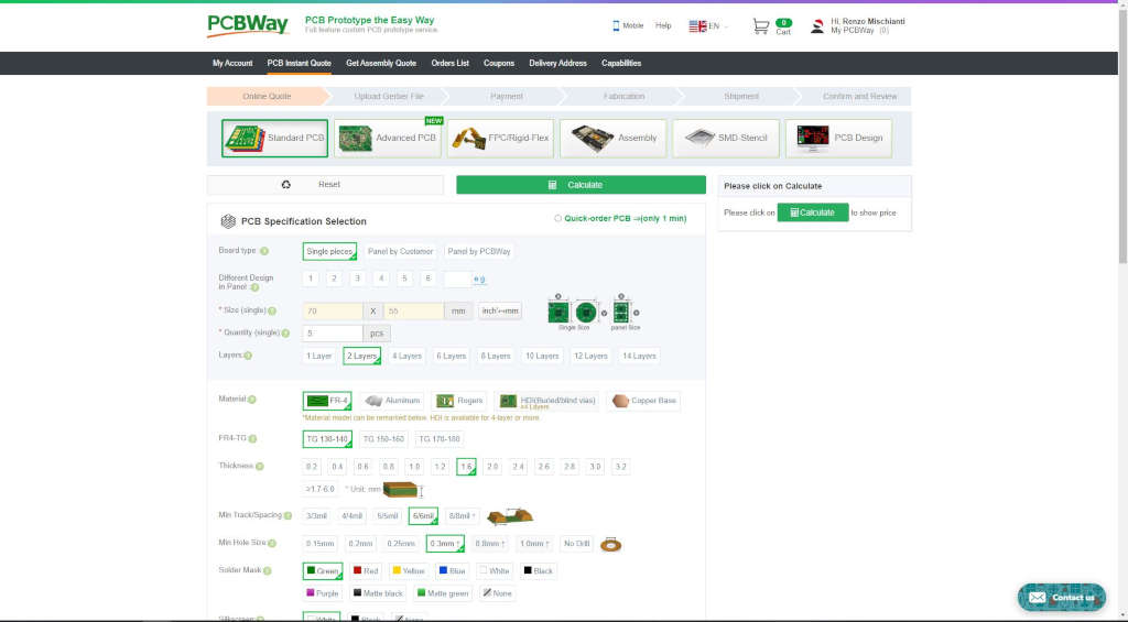
You can get pcb without additional costs here from PCBWay

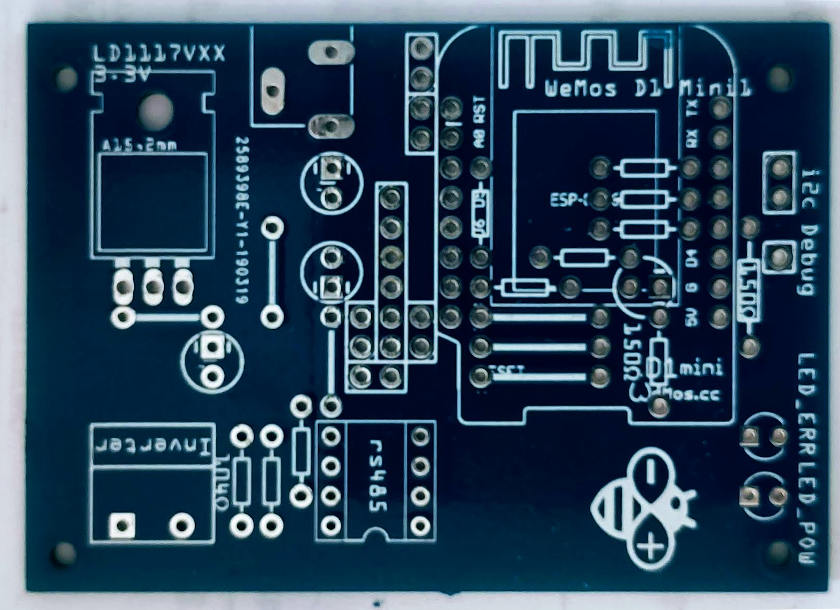
Welding also is simple, you just have to follow the screen printing, in the latest version it is more descriptive and intuitive (in this photo you can see the screen printing of all the components without distinction, but in the new one it is specified which minimal components you have to insert, and “No” on the optional ones, added in case of interference).
You can get pcb without additional costs here from PCBWay

When the board is assembled the result will be this
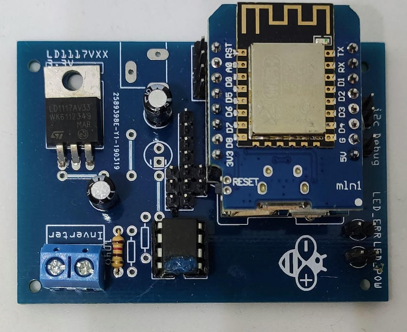
As you can see not all holes are used, when I created the board I added more components to use if there was some noise, but I never had such disturbances that I had to add more components than the basic ones.
So you only need the Voltage regulator the MAX3485, 2 capacitor, 3 resistor and the WeMos D1 battery shield.
PCB list of material and soldering instruction
| Amount | Part Type | Properties |
|---|---|---|
| 2 | Electrolytic Capacitor | capacitance 10µF |
| 1 | Generic male header – 1 pins | pin spacing 0.1in (2.54mm); form ♂ (male) |
| 6 | Generic male header – 2 pins | pin spacing 0.1in (2.54mm); form ♂ (male) |
| 1 | Camdenboss CTB0158-2 | pin spacing 0.2in (5.08mm); hole size 2.7mm; variant 90° 2 connector; |
| 1 | Generic male header – 6 pins | pin spacing 0.1in (2.54mm); form ♂ (male) |
| 1 | 104Ω Resistor | pin spacing 400 mil; resistenza 104Ω; tolerance ±5%; bands 4; package THT |
| 2 | 150Ω Resistor | pin spacing 400 mil; resistenza 150Ω; tolerance ±5%; bands 4; package THT |
| 1 | MAX485 | variant dil; package dil08 |
| 1 | LD1117V33 | voltage 3.3V; package 78xxl; chip LD1117VXX |
| 1 | WeMos D1 Battery shield | |
| 1 | WeMos D1 Mini | cpu ESP-8266EX; |
Here some link where you can find the components:
WeMos D1 mini on WeMos D1 mini - NodeMCU V2 V2.1 V3 - esp01 - esp01 programmer
WeMos Battery shield on AliExpress
LD1117V33 Voltage regulator on AliExpress SMD (AMS1117) - AliExpress 3.3v (LM1117) - AliExpress 5v (7805) - AliExpress 9v (7809)AliExpress 12v (7812) - AliExpress 3.3v TO-92 (78L33)
MAX3485 IC on AliExpress
Then you can start to assembly, here a simple video that show all the step
SD card connection
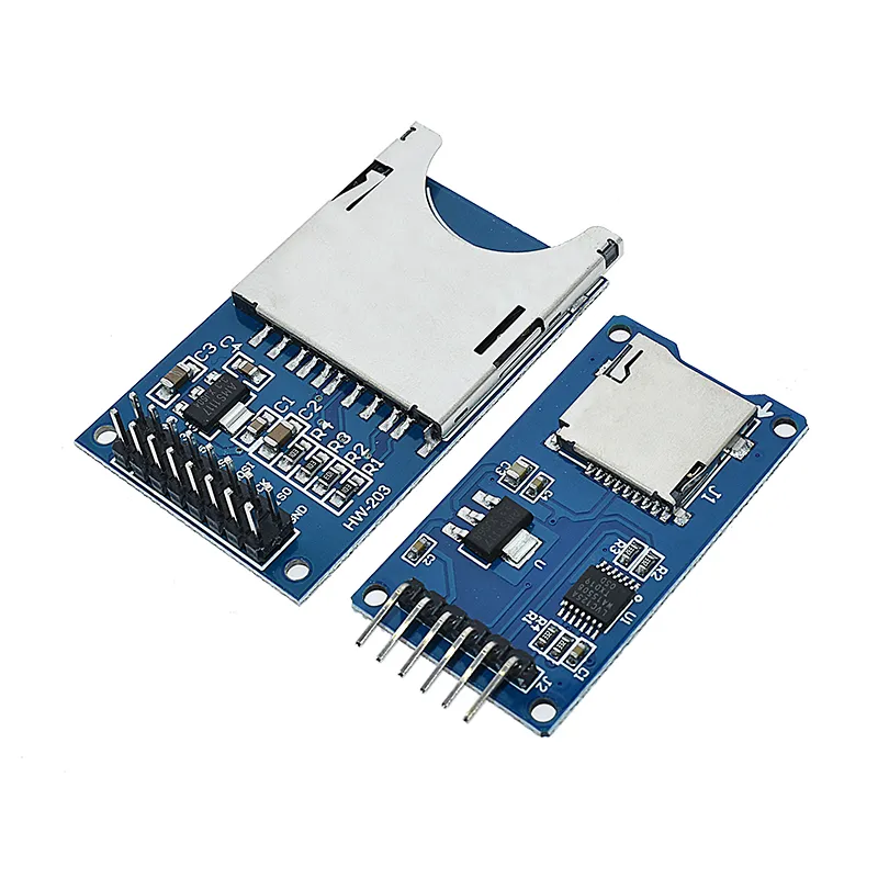
To complete the project you must have an SD card module, I select the SD because the industrial grade are SD not microSD.
- The connector of battery from the top
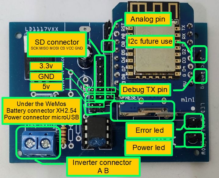
SCK MISO MOSI CS VCC GND
SD card module AliExpress
- Then you need 2 led dupont
Dupont on AliExpress
- the battery connector XH2.54 male
XH2.54 male connector battery on AliExpress XH2.54 2.54mm AliExpress PH2.0 2.0mm
- a switch and a push button
2 position switch Aliexpress
Push button for reset AliExpress
Battery adapter
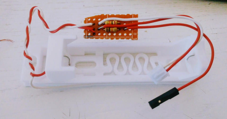
I use the battery shield for WeMos D1 mini, but It’s work like the power bank example, there is a charging regulator and a step-up module to stabilize voltage at 5v, refer “Emergency power bank homemade“.
Then you need to create a voltage divider to check the battery voltage on A0, for this you can refer to the diagram in this article “Voltage divider: calculator and application” and related video
Now you can follow this schema to connect the basic elements of the board
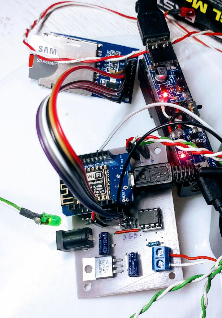
At the end you should find yourself in this situation
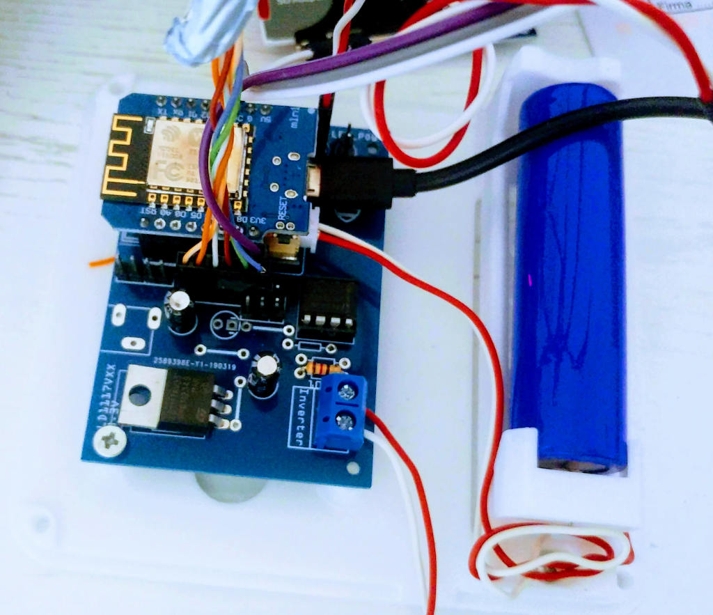
You will find that it is quite easy to install all components.
Thanks
- ABB Aurora Web Inverter Monitor (WIM): project introduction
- ABB Aurora Web Inverter Monitor (WIM): wiring Arduino to RS-485
- ABB Aurora Web Inverter Monitor (WIM): storage devices
- ABB Aurora Web Inverter Monitor (WIM): debug and notification
- ABB Aurora Web Inverter Monitor (WIM): set time and UPS
- ABB Aurora Web Inverter Monitor (WIM): WIFI configuration and REST Server
- ABB Aurora Web Inverter Monitor (WIM): WebSocket and Web Server
- ABB Aurora Web Inverter Monitor (WIM): Wiring and PCB soldering
- ABB Aurora Web Inverter Monitor (WIM): upload the sketch and front end
- ABB Aurora web inverter Monitor (WIM): 3D printed case to complete project
- ABB Aurora web inverter monitor (WIM): repair E013 error
GitHub repository with all code BE and FE transpiled




Hello, did you also publish the pcb somewhere else? I can mill my own pcb’s so it would be handy if I can do it by myself. I checked your github pages, but couldn’t find the design there.
Where did you pull the power for the logger ? I have a 5000TL-OUTD, which powers off when there’s no solar, but I don’t see (yet) the possibility to draw 5V from the pcb somewhere to power the board. I had a solarlog200, but it gave up over a year ago; so I stumbled accidently accros your site and do plan to build this monitor to have my system logging again.
Thanks!
Hi Ziporah,
the PCB is only on PCBWay (we have a deal).
I use a 12v to USB module https://s.click.aliexpress.com/e/_AWvOim but i found 12v ready when they install my inverter, I add a battery to prevent the power off of centraline when no solar power.
Bye Renzo
Hi Renzo, Nice project that I’m planning to realize.
May I ask you where you found your 12v power in your Aurora?
K R , Marc
Hi Marcs,
sorry but I reuse the exist power supply from the previous datalogger
But if i remember they add a voltage regulator from the 220v of the exit of the solar panel
Bye Renzo
First of all, thank you for this project. I have already ordered the PCB. The only thing I could not find is the complete wiring diagram. Did I missed something, or it’s not available?
Thank you for your reply.
Sasa Michaljanic
Hi Sasa,
no I don’t do the wiring diagram (when I have some time I’m going to do It), the only think you need is in the schema.
The SD adapter pin, the connector of the battery in the battery shield and the voltage divider pin of the battery in the ADC pin of the PCB.
But if you have some trouble ask to me, or open a topic in the forum.
Bye Renzo
Hi Renzo,
I wanted to express my gratitude for your hard work and for sharing your project. I’ve managed to recreate it, and currently, the web app is running smoothly. The card is logging, and the battery, along with the battery shield, are performing their functions as expected.
Now, my next step is to connect it to the inverter. I do have a question that might sound a bit basic, but I couldn’t find a clear answer in your article. When connecting A and B, should they be directly linked to +T/R and -T/R? I’m asking this because you also mention LNK and RTN, and it’s a bit unclear to me whether these need to be used or connected to the board.
Additionally, I’m curious about how you power the board. Do you use an external power supply for that?
Thanks a lot in advance for your assistance.
Hi Vincenzo,
you can find the information you need in this article
Centralina Web per inverter ABB Aurora (WIM): connessione Arduino all’RS-485 – 2
For the Power supply I can’t help you because I reuse the wire from the other centraline that I substitute.
Bye Renzo