
RYUW122_Lite (UWB): high resolution pinout, datasheet, schema, and specifications
Ultra-Wideband (UWB) technology represents a turning point in precision location systems, offering centimeter-level accuracy unattainable with other wireless technologies. The REYAX RYUW122_Lite emerges as a key component in making this technology accessible to developers, makers, and engineers.
You can find here Reyax distributor RYUW122_lite - Amazon RYUW122_lite - First Components RYUW122_lite
The “RYUW122_Lite” is a “lite version of the evaluation board”. This board is specifically designed to “understand and test the REYAX RYUW122 module more quickly”. The heart of the system is, therefore, the RYUW122 module, a surface-mount (SMD) component. The RYUW122_Lite, conversely, is its “DIP version” counterpart, which mounts the RYUW122 module onto a small PCB with a 6-pin header, making it ideal for rapid breadboard prototyping.
The “Lite” designation refers not to reduced UWB functionality but to the evaluation board’s simplicity and accessibility. A more complex “RYUW122_DK Positioning Development Kit” also exists for full-scale positioning tests. The RYUW122_Lite is, therefore, the low-cost entry point for interfacing and prototyping.
UWB competitors (when do you need to use them?)
Precision & Reliability (The “Hero”: UWB)
UWB (Ultra-Wideband) stands out as the most robust technology for precise location tracking.
- Strengths: It offers centimeter-level accuracy, the lowest latency (<1ms), and the highest security (resistant to relay attacks). It is also highly immune to interference.
- Best For: Real-time asset tracking, secure entry access, and industrial applications where precision is critical.
Data Speed & Connectivity
Wi-Fi is the undisputed leader for data transfer, but struggles with precise location.
- Strengths: Massive data throughput (up to 1Gbps).
- Weaknesses: It consumes the most power (requires lithium batteries), has low location accuracy (5–15 meters), and high latency for positioning (>3s).
- Best For: High-bandwidth data communication rather than tracking.
Cost-Effective Proximity
Bluetooth serves as a general-purpose, low-cost option.
- Strengths: Low implementation cost ($) and decent power efficiency.
- Weaknesses: It is susceptible to interference and obstructions, making it less reliable for critical tracking. Accuracy is moderate (1–5 meters).
- Best For: Consumer proximity detection (like finding lost keys), where occasional inaccuracy is acceptable.
Logistics & Scalability
RFID and GPS fill specific niche roles based on range and power.
- RFID: Unique because it is passive (no battery required on tags). It has unlimited scalability but a very short range (1 meter). It is ideal for inventory scanning.
- GPS: The standard for outdoor tracking with unlimited scalability. However, it cannot be used indoors and has the lowest accuracy (5–20 meters).
Summary Verdict
- Choose UWB if you need high precision, security, and real-time speed indoors.
- Choose Wi-Fi if you need to move large amounts of data.
- Choose RFID for scanning thousands of items at a low cost, without batteries.
- Choose Bluetooth for cheap, “good enough” proximity tracking.
| Feature | UWB | Bluetooth | Wi-Fi | RFID | GPS |
| Where Used | Outdoor / Indoor | Outdoor / Indoor | Outdoor / Indoor | Outdoor / Indoor | Outdoor |
| Accuracy | Centimeter | 1-5 meters | 5-15 meters | Centimeter to 1 meter | 5-20 meters |
| Reliability | ⭐⭐⭐⭐⭐ Strong immunity to multi-path and interference | ⭐⭐ Very sensitive to multi-path, obstructions and interference | ⭐⭐ Very sensitive to multi-path, obstructions and interference | ⭐⭐⭐⭐ | ⭐⭐⭐ Very sensitive to obstructions |
| Range / Coverage | Typ. 70m (Max 250m) Typ. 250m² per anchor | Typ. 15m (Max 100m) Typ. 25m² per beacon (for 2m accuracy) | Typ. 50m (Max 150m) Typ. 100m² per access point (for 5m accuracy) | Typ. 1m (Max 5m) Typ. 25m² per reader | N/A |
| Data Communications | ✅ up to 27Mbps | ✅ up to 2Mbps | ✅ up to 1Gbps | ❌ | ❌ |
| Security (PHY Layer) | ⭐⭐⭐⭐⭐ Distance-Time bounded protocol | ⭐⭐ Can be spoofed using relay attack | ⭐⭐ Can be spoofed using relay attack | ⭐⭐ Can be spoofed using relay attack | N/A |
| Latency | ⭐⭐⭐⭐⭐ Typ. <1ms to get XYZ | ⭐⭐ Typ. >3s to get XYZ | ⭐⭐ Typ. >3s to get XYZ | ⭐⭐⭐ Typ. 1s to get XYZ | ⭐⭐ Typ. 100ms to get XYZ |
| Scalability Density | ⭐⭐⭐⭐ >10’s of thousands of tags | ⭐⭐⭐ Hundreds to a thousand tags | ⭐⭐ Hundreds to a thousand tags | ⭐⭐⭐⭐⭐ Unlimited | ⭐⭐⭐⭐⭐ Unlimited |
| Power & Battery | 5nJ/b TX · 9nJ/b RX (Coin Cell) | 15nJ/b RX/TX (Coin Cell) | 50nJ/b RX/TX (Lithium Battery) | Passive | Lithium Battery |
| Total Cost | $ | $ | $$$ | $$$ | $$$ |
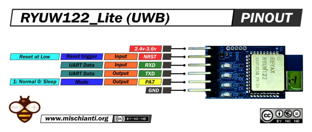
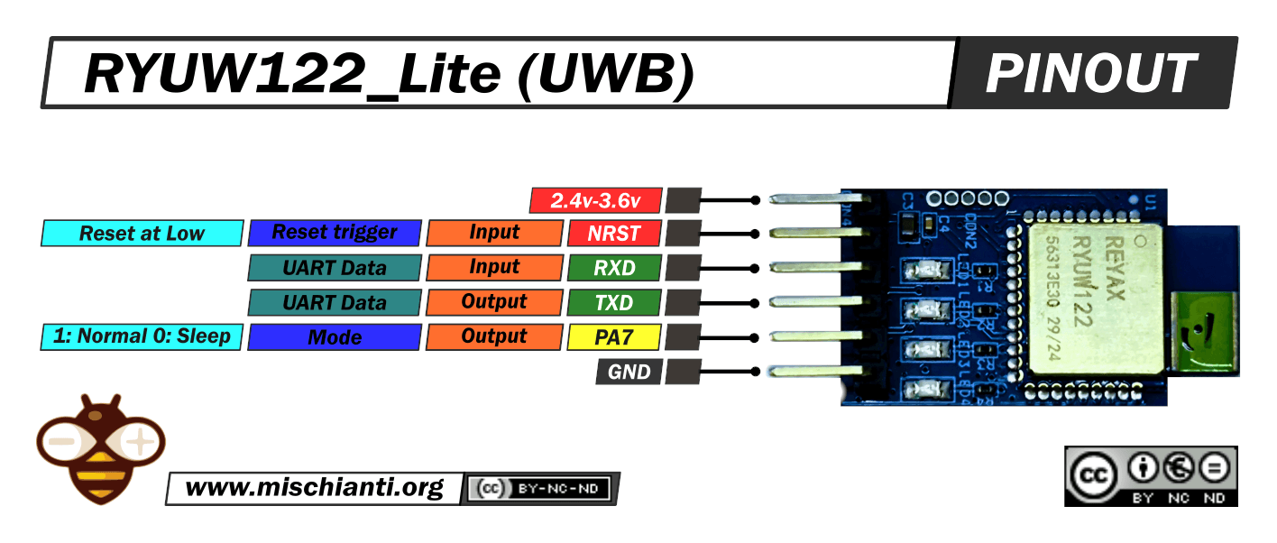
Hardware and Pinout
The hardware analysis reveals two levels: a 6-pin DIP interface for basic functions and a deeper schematic analysis that exposes advanced debug capabilities.
6-Pin DIP Header
Interaction with the board primarily uses the 6-pin male header, which exposes essential power and UART interfaces.
| Pin | Name | I/O | Description |
| 1 | VDD | P | Power Supply |
| 2 | NRST | I | Low reset trigger input |
| 3 | RXD | I | UART Data Input |
| 4 | TXD | O | UART Data Output |
| 5 | PA7 | O | Mode Indicator (Hi: Normal mode, Low: Sleep mode) |
| 6 | GND | P | Ground |
- Key Pin Analysis (Pin 5 – PA7): This is not a general-purpose GPIO. It is an Output pin actively managed by the module’s firmware to indicate its power state. This allows a host MCU to monitor if the module is active (“Normal mode”) or in its low-power “Sleep mode” without needing to send polling commands.
PCB components
The official schematic reveals functionality beyond the 6-pin header:
- Core Component: The central component is
U1, the 30-pin REYAX RYUW122 SMD module. The “Lite” board acts as its carrier. - On-board LED Indicators: The schematic shows four LEDs (LED1-LED4). The module pins driving them provide specific hardware feedback on the UWB transceiver’s status:
GPIO0/RXOKLED: Indicates correct packet reception.GPIO1/SFDLED: Start of Frame Delimiter, indicates packet detection.GPIO2/RXLED: Indicates receive activity.GPIO3/TXLED: Indicates transmit activity.
- Debug & Expansion Headers: The board includes unpopulated connectors:
CON2: A connector for Serial Wire Debug (SWD) programming/debugging, exposingSWCLK,NRST, andSWDIO.CON4: A 6-pin header exposing a richer signal set, includingTXD,RXD,SWCLK,SWDIO, and notably,SCLandSDAfor I2C.
- Reference Components: The schematic includes an
ST LIS3DHTRaccelerometer. While not populated on the standard “Lite” board, its inclusion suggests advanced use cases for motion-activated tags.
This schematic confirms the presence of an accessible internal MCU, opening two distinct development paths:
- Application Developer (Standard Path): Uses the 6-pin DIP header, interfaces via UART, and controls the module using the pre-installed REYAX AT command firmware.
- Firmware Developer (Advanced Path): Connects to the SWD headers (CON2/CON4), bypasses the AT firmware, and programs the internal MCU directly for custom, high-performance applications.
Technical Specifications
The RYUW122_Lite’s performance is defined by the core RYUW122 module it hosts. The following tables consolidate specifications from multiple datasheets.
Core Features
- UWB Standards: IEEE802.15.4-2015 UWB & IEEE802.15.4z (BPRF mode).
- Security: Integrated AES 128 hardware encryption.
- Control Interface: AT commands over UART.
- Antenna: Integrated UWB antenna on the module PCB.
- Functionality: Provides precision location measurement and data transfer simultaneously.
- Compliance: Worldwide UWB Radio Regulatory compliance.
Technical Specifications Table
| Category | Parameter | Min | Typical | Max | Unit | Condition |
| RF Specs | Frequency Range | 6489.6 | – | 7987.2 | MHz | Channel 5 & Channel 9 |
| Bandwidth | 850 | – | 6.8 | KHz / MHz | ||
| Location Accuracy | – | 10 | – | cm | Open Field Environment | |
| Communication Range | – | 100 | – | M | RYUW122-to-RYUW122, Open Field | |
| RF Sensitivity | -100 | – | – | dBm | ||
| Power | Voltage – Supply (VDD) | 2.4 | 3.3 | 3.6 | V | |
| ANCHOR mode Current | – | 8 | – | mA | ||
| TAG mode Current | – | 81 | – | mA | ||
| Current – Receiving | – | 181 | – | mA | ||
| RF Transmit Current | – | 86 | – | mA | ||
| RF disable Current | – | 4 | – | uA | ||
| Sleep Mode Current | – | 2 | – | uA | ||
| Digital I/O | Digital Input High (VIH) | 0.7*VDD | – | VDD | V | |
| Digital Input Low (VIL) | 0 | – | 0.3*VDD | V | ||
| Digital Output High (VOH) | 0.9 | – | VDD | V | ||
| Digital Output Low (VOL) | 0 | – | 0.1 | V | ||
| Physical | Operating Temperature | -40 | 25 | +85 | ˚C | |
| Weight | – | 1 | – | g |
Key Specification Analysis
- Power Consumption: A critical design constraint is the asymmetric power profile. “ANCHOR mode” (8 mA) consumes far less power than “TAG mode” (81 mA). This is because the Tag is mobile (battery-powered) and must handle high-power transmission (86 mA) and reception (181 mA). For any battery-powered Tag, extensive use of the “Sleep Mode” (2 uA) is mandatory. This makes the
AT+MODE=2command and thePA7status pin vital features. - Logic level: You can directly connect only if you use a 3.3V MCU; for a 5V MCU, such as the Arduino UNO, you must use a voltage divider or logic level converter.
Interfacing and Programming
The module’s primary advantage is its AT command interface, allowing any MCU with a UART to perform UWB ranging.
UART Configuration
- Default Settings: 115200 bps, 8 data bits, no parity, 1 stop bit (8-N-1).
- Command Logic: All AT commands sent to the module must terminate with a carriage return/line feed (
\r\n). - Control Flow: You must wait for the
+OKresponse from the module before sending the next command. - Baud Rate Change: The baud rate is configurable (e.g., 9600, 57600) and can be saved to flash using the
AT+IPRcommand.
Essential AT Commands for Ranging
The AT command set provides full control. The table below lists the fundamental commands for a ranging system.
| Command | Example Syntax | Description |
| Test | AT | Tests communication. Module responds with +OK. |
| Reset | ATZ | Performs a software RESET of the module. |
| Set Role | AT+MODE=1 | Sets the module’s role: 0 = TAG (Default), 1 = ANCHOR, 2 = SLEEP. |
| Query Role | AT+MODE? | Queries the currently set role. |
| Set Network ID | AT+NETWORKID=REYAX123 | Sets the network ID (8 ASCII bytes). Only modules with the same ID can communicate. |
| Set Address | AT+ADDRESS=TAG_0001 | Sets the module’s unique address (8 ASCII bytes). |
| Query UID | AT+UID? | Reads the module’s 96-bit unique ID. |
| Set Channel | AT+CHANNEL=9 | Sets the RF channel: 5 = 6489.6MHz (Default), 9 = 7987.2 MHz. |
| Set Bandwidth | AT+BANDWIDTH=1 | Sets the data rate: 0 = 850 Kbps (Default), 1 = 6.8 Mbps. |
| Ranging (Anchor) | AT+ANCHOR_SEND=TAG_0001,4,TEST | Key Command. Sent from an ANCHOR. Sends 4 bytes of data (“TEST”) to the TAG with address “TAG_0001” and initiates distance measurement. The response will include the calculated distance. |
| Send Data (Tag) | AT+TAG_SEND=4,DATA | Sent from a TAG. Sends 4 bytes of data (“DATA”) to the anchor. |


