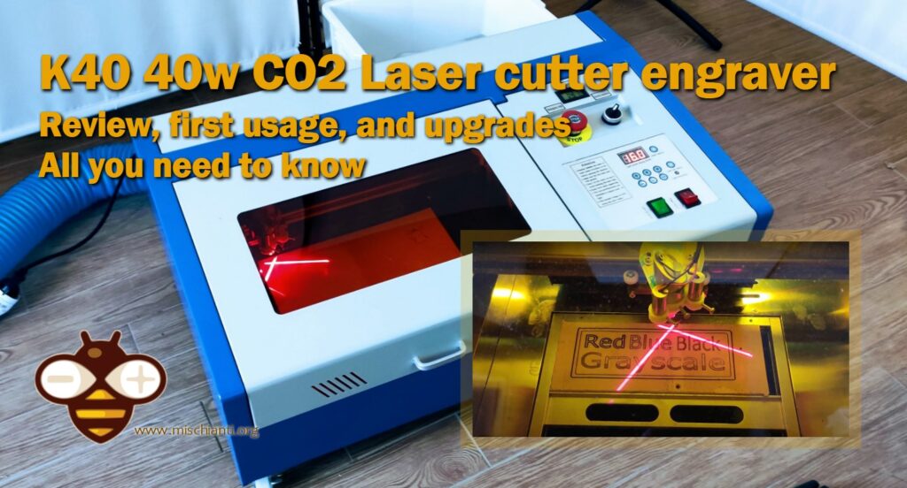
K40 40w CO2 Laser cutter engraver: review, first usage, and upgrades (all you need to know)
The K40 CO2 laser cutter is an affordable and versatile tool popular among DIY enthusiasts and small-scale fabricators. Before investing in this 40W machine, it’s crucial to understand its features, capabilities, and the adjustments you might need to make to optimize its performance.
Specifications
Basic Specifications
- Laser Type: CO2 gas laser
- Laser Power: 40 watts
- Work Area: Typically 300mm x 200mm (12″ x 8″)
- Material Capability: Capable of cutting materials like wood, acrylic, leather, paper, and engraving on coated metals and anodized aluminum.
- Cooling: Water-cooled system, typically using a basic external water pump to circulate water.
- Control Interface: Comes with a standard M2 Nano board which users often replace with more advanced controllers.
- Software Compatibility: Compatible with various software including K40 Whisperer, LightBurn (with a controller upgrade), and the original software often called LaserDRW or CorelLaser.
Performance Features
- Precision: Can achieve a resolution of up to 1000 dpi, which is suitable for detailed engraving work.
- Speed: Cutting speed can vary depending on the material, but it generally supports up to 350 mm/s which can be adjusted for finer engraving or faster cuts.
- Power Supply: Equipped with a standard 110V/220V power supply.
Design and Build
- Structure: Generally made of a steel frame with a plexiglass viewing cover, allowing users to monitor the laser process.
- Safety Features: Includes safety interlocks that cut power to the laser when the machine cover is opened.
- Ventilation: Requires external exhaust to a fume extraction system or outdoor venting to handle the fumes produced during cutting and engraving.
Overview of the K40 CO2 Laser Cutter
The K40 laser cutter is a compact device that uses a 40W CO2 laser tube to cut and engrave various materials, including wood, acrylic, and leather. It’s known for its relatively low cost compared to other laser cutters on the market, making it an attractive option for beginners and those with a limited budget.
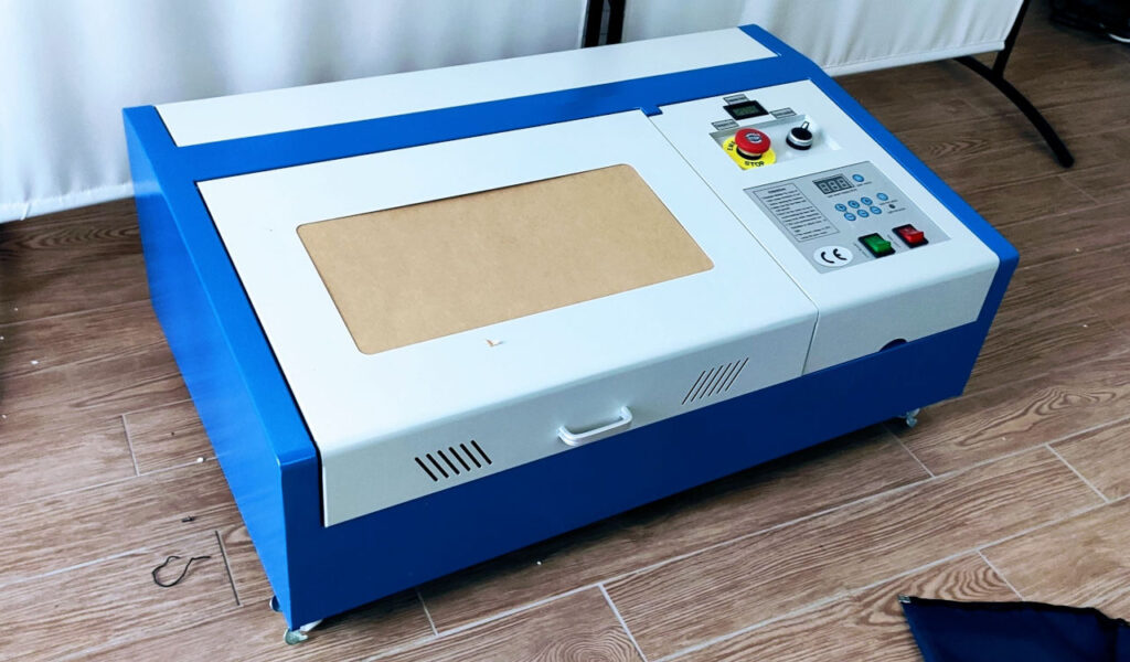
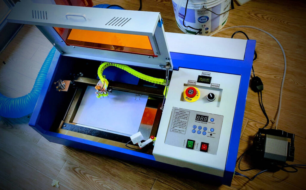
Here is a photo of the laser just arrived.
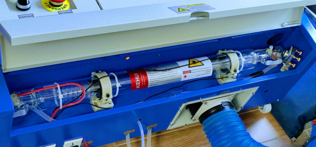
Here a detail of the inside.
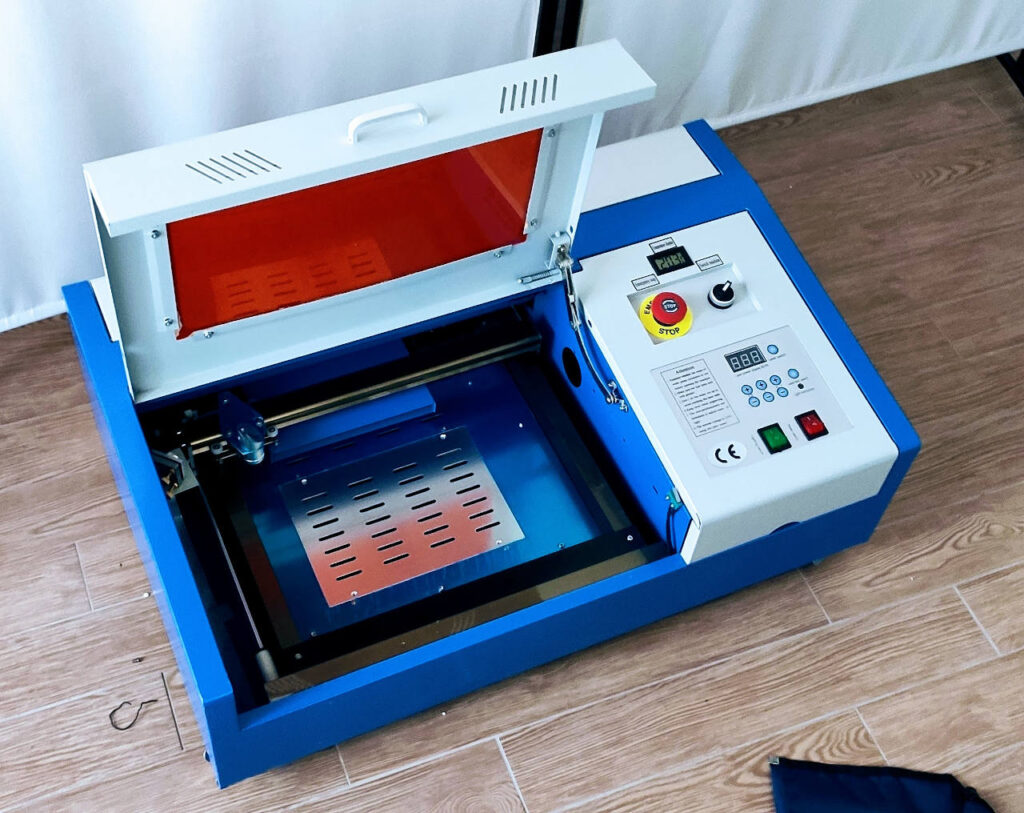
As you can see, you must remove all the protective plastic from the glass door and the metal part.
In the latest version of the laser the constructors add the temperature of the water, very important to preserve the laser tube, and the inside light useful to follow the laser work.
Here the laser ordered K40 Laser CO2 Laser Head with air assist
Key Features
- Power and Precision: The 40W laser is capable of cutting through materials up to 4mm thick with a reasonable degree of precision. It’s suitable for small-scale projects and crafts.
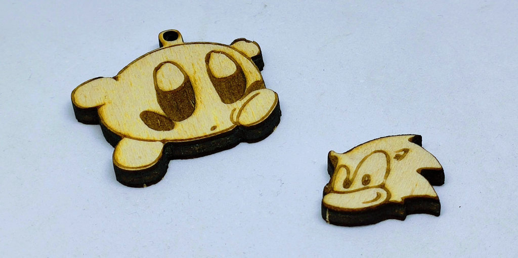
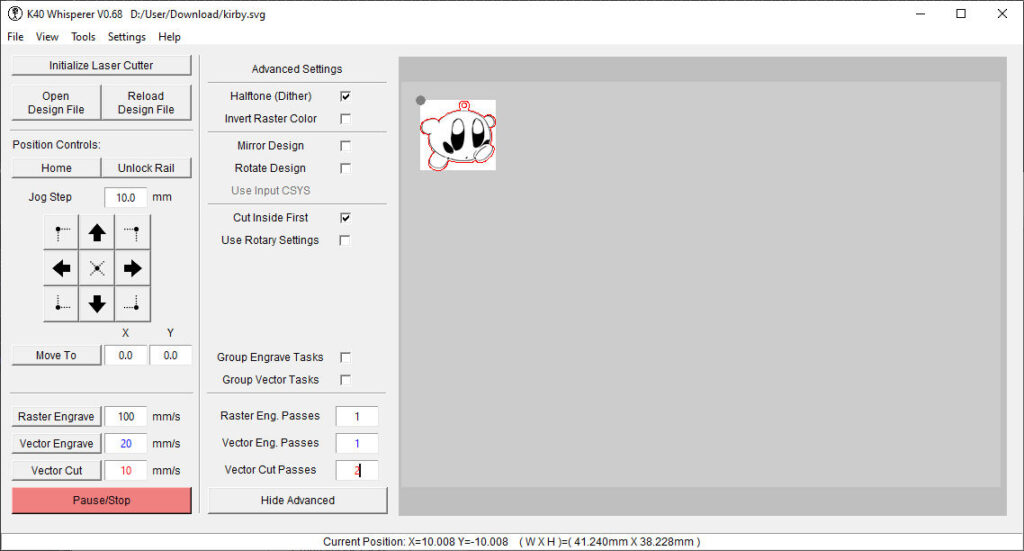
- Software Compatibility: The machine typically comes with basic software, which is often limited. Many users upgrade to more robust software like K40 Whisperer or LightBurn for enhanced functionality.
- Build Quality: The K40’s build quality can vary. Some components, like the laser tube and power supply, may need upgrading or may require careful calibration to ensure optimal performance. My K40 laser, linked here, is quite good. I didn’t change the power supply pump and laser tube. The glasses are good, and the lens is clean.
The first operations to do
When setting up your K40 CO2 laser cutter for the first time, it’s crucial to follow a structured setup process to ensure it operates safely and effectively.
Removing Protective Plastic
Begin by carefully removing all protective plastic coverings from the machine. These coverings are placed to protect the cutter during shipping, but they can hinder performance and potentially trap heat if not removed.
Connecting the Air Extraction Tube
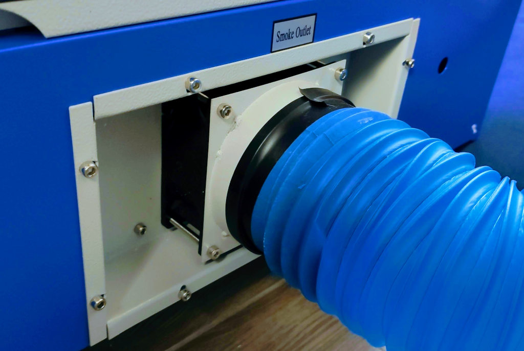
Next, connect the air extraction tube. This component is essential for ventilating smoke and fumes generated during the cutting process, helping to maintain a safe working environment and protect the machine’s internal components.
Setting Up the Water Flow Pump
Lastly, the water flow pump is set up, which is crucial for cooling the laser tube during operation. Ensuring proper water flow will prevent the laser from overheating, thereby extending its lifespan and maintaining consistent performance.
Taking these initial steps methodically will set a strong foundation for safe and efficient operations.
Importance of Mirror Alignment
The K40 laser’s performance heavily depends on the proper alignment of its mirrors, a process that can be both meticulous and critical. Misalignment can lead to inconsistent cuts, reduced efficiency, and potential damage to materials. To achieve optimal alignment:
Clean the Mirrors
Before starting the alignment, ensure that all mirrors are clean and free from debris.
Adjust the Laser Tube
The laser tube should be securely mounted and aligned with the first mirror at the back of the machine.
Adjusting the laser tube in your K40 laser cutter is a crucial step to ensure that the laser beam is accurately aligned with the system’s optical path. This alignment is vital for achieving clean cuts and precise engravings. One effective method for adjusting the laser tube involves using paper tape. Here’s a step-by-step guide on how to do this:
- Secure the Laser Tube: first, ensure that the laser tube is securely mounted in its holder at the back of the machine. The tube should not move or wobble, as stability is key to maintaining alignment over time. Check that all clamps or brackets holding the tube are tightened and that the tube is level.
- Position Paper Tape on the First Mirror: place a small piece of paper tape over the center of the first mirror. This mirror is typically located at the back of the machine, directly in line with the laser tube. The tape should be big enough to cover most of the mirror but not so large that it hangs off the edges.
- Fire the Laser at Low Power: turn on the laser cutter and set it to the lowest power setting necessary to make a visible mark on the tape. This is crucial to avoid damaging the mirror and the tape. Once set, fire the laser briefly to mark the tape. The goal here is to see where the laser hits the tape.
- Adjust the Laser Tube: check the mark on the tape. Ideally, the mark should be at the very center of the tape. If it is not, you will need to adjust the position of the laser tube. This can be done by slightly loosening the mounts that hold the tube, then shifting the tube gently until it aligns with the center of the mirror. After each adjustment, replace the tape with a fresh piece and fire the laser again to check the new position of the mark.
- Repeat Until Centered: continue adjusting the laser tube and firing the laser, placing fresh tape as needed, until the mark consistently lands in the center of the mirror. This indicates that the laser tube is properly aligned with the first mirror.
- Secure the Tube: once the laser beam is centered on the first mirror, tighten the mounts or clamps of the laser tube to secure it in place. It’s important to ensure the tube doesn’t shift during this final tightening.
- Final Check: after securing the tube, it’s a good idea to do one final test fire with a fresh piece of tape to confirm that everything remains perfectly aligned after the adjustments.
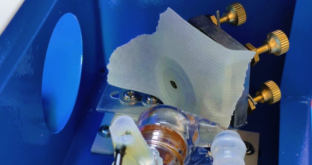
Set the First Mirror
Adjust this mirror so that the laser beam hits the center of the second mirror.
- Prepare the First Mirror: Ensure the laser tube alignment has been previously adjusted correctly.
- Place Paper Tape on the Second Mirror: Attach paper tape across the entire surface of the second mirror, where the beam should land.
- Test Fire at Low Power: Power on the laser cutter, set it to a low power mode, and briefly fire the laser to mark the tape on the second mirror.
- Assess Beam Position: Check where the beam hits the tape. The goal is for the mark to be exactly in the center of the mirror.
- Adjust the First Mirror: Using the adjustment screws on the first mirror mount, tilt the mirror to alter the beam’s direction. Adjust one screw at a time, then test fire and observe the position of the beam on the tape.
- Repeat Adjustments: Continue making small adjustments to the mirror and test firing until the beam consistently hits the center of the second mirror. Replace the tape as needed to keep track of new marks clearly.
- Secure the Adjustment: Once the beam is centered, tighten the screws on the first mirror mount to secure the mirror in place. Avoid over-tightening to prevent shifting the alignment.
- Final Verification: Conduct a final test fire and check the position of the beam on the second mirror to confirm the alignment is correct.
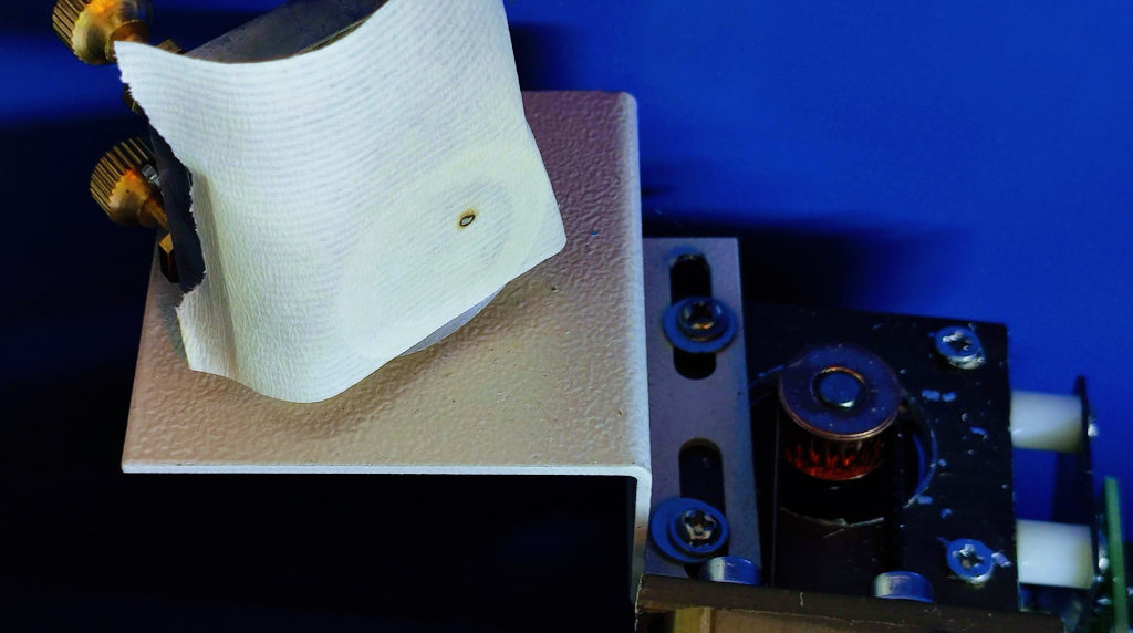
Align the Second Mirror
This mirror directs the beam to the third mirror, usually located on the moving head.
- Prepare the Second Mirror: Start by ensuring that the first mirror is already properly aligned and directing the beam to the center of the second mirror.
- Attach Paper Tape to the Third Mirror: Place paper tape on the surface of the third mirror. Since this mirror moves with the cutting head, ensure the head is positioned in such a way that you can easily access it for adjustments.
- Test Fire at Low Power: Fire the laser at a low power setting to mark the tape on the third mirror. This initial mark will help you assess the current alignment.
- Assess the Beam’s Position: Check where the laser beam hits the tape on the third mirror. The goal is to have the beam hit the center of the tape. If the mark is off-center, adjustments to the second mirror are necessary.
- Adjust the Second Mirror: Adjust the screws on the second mirror mount to tilt the mirror and change the direction of the beam. These screws typically allow for horizontal and vertical movement. Adjust one axis at a time, make a small adjustment, then test fire again to see the effect.
- Repeat the Adjustment Process: Continue adjusting and test firing, applying new pieces of tape as needed until the beam consistently hits the center of the third mirror. Remember to move the cutting head to different positions along the X and Y axes and repeat the firing to ensure the beam remains centered across the entire range of motion.
- Secure the Mirror: Once you’ve achieved consistent centering of the beam on the third mirror, tighten the adjustment screws on the second mirror mount to lock the mirror in place. Ensure the adjustments are secure but be cautious not to shift the alignment while tightening.
- Final Check: Perform a final test fire with the third mirror at various points of the cutting bed to confirm that the beam remains centered in all positions. This ensures that the machine will perform accurately during actual operations.
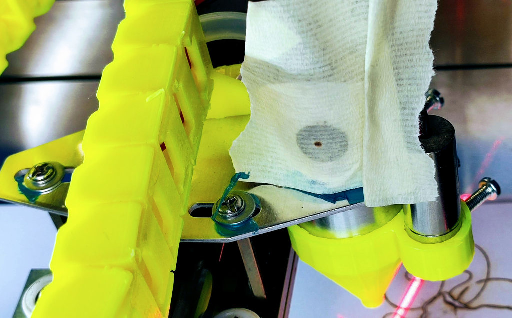
Examine the result
Ensure the beam is centered through the lens and onto the workpiece.
This meticulous alignment ensures that the laser path is as straight as possible, leading to precise and clean cuts.
Important upgrade
I will detail these updates in future articles, but for now, I will settle for an overview to give a general idea of the various needs.
Adding an Air Assist System
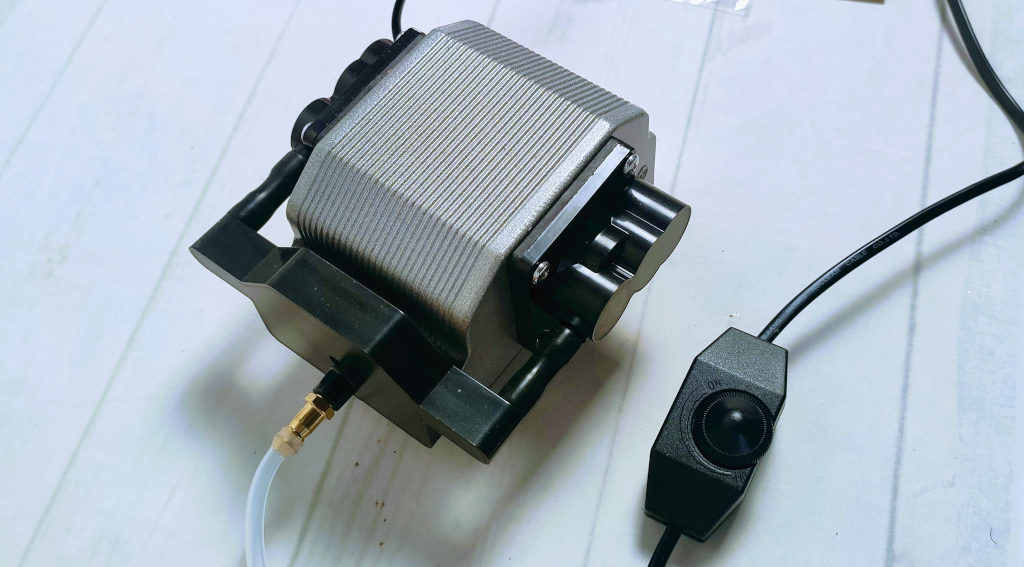
Here is my budget-friendly and effective selection 30L/Min Air Assist Pump
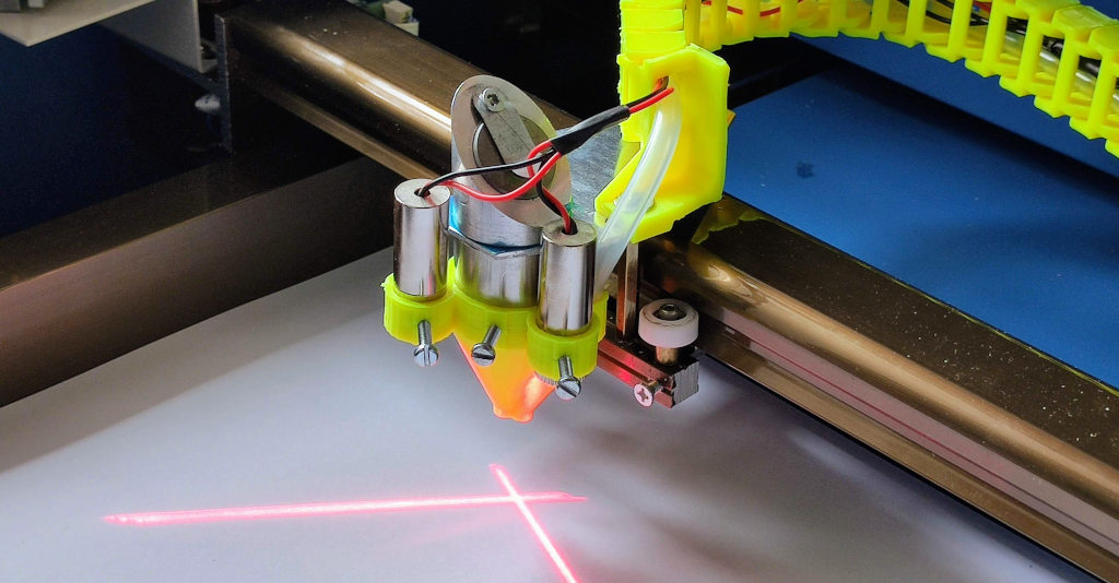
Air assist is crucial in any laser cutting process, as it helps to clear smoke away from the cutting path, reduces the chance of flammable ignitions, and keeps the cutting area clean. My setup includes a custom-designed nozzle and a cable chain both 3D-printed, which provide a streamlined and functional design. Key features of this system include:
- Custom-Designed Nozzle: The nozzle directs a steady stream of air precisely where the laser contacts the material, effectively removing debris and minimizing thermal damage.
- 3D-Printed Cable Chain: This addition helps in managing the tubing and wires, keeping the workspace organized and reducing the risk of entanglements or snags.
Optional upgrade
Laser Diode Crosshairs
To enhance precision, I installed two laser diodes that project an “X” at the focal point of the CO2 laser beam. This crosshair significantly simplifies the task of positioning the material precisely under the laser, ensuring accuracy in starting points and reducing material waste.
Integration of ESP32-CAM
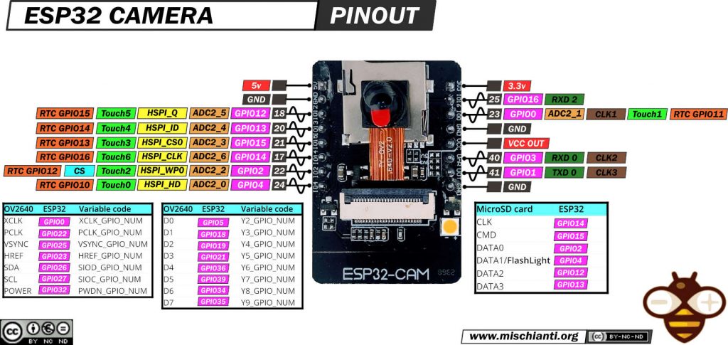
Monitoring the cutting process can be challenging, particularly in intricate or prolonged operations. By incorporating an ESP32-CAM into the setup, I can now remotely monitor the laser cutter in real-time. Key aspects of this modification include:
- Camera Enclosure: The camera is housed in a custom-designed 3D-printed enclosure that shields it from dust and debris while providing an optimal viewing angle.
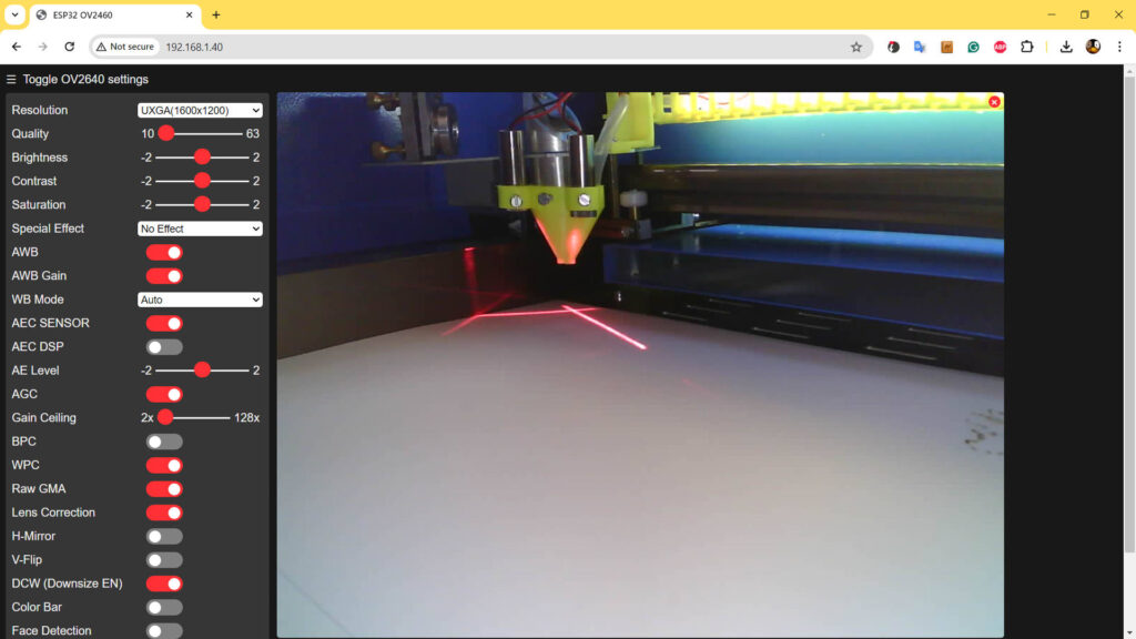
- Software Configuration: The ESP32-CAM is configured to stream live video, which can be accessed via a network connection, allowing for remote monitoring and control.
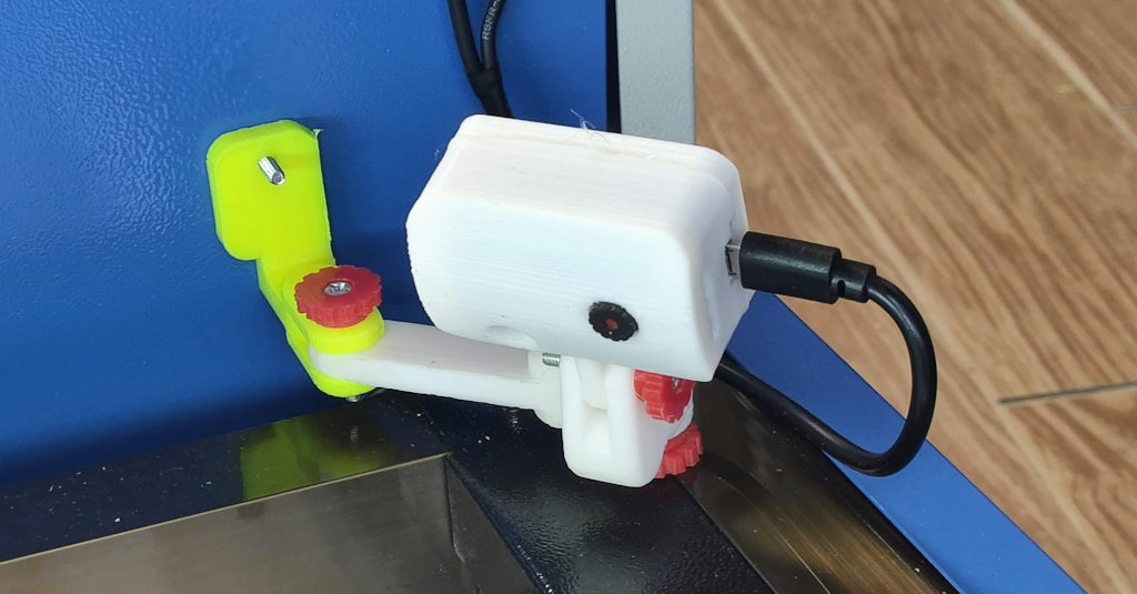
This camera system not only adds a layer of convenience but also enhances safety, allowing for immediate action should any issues arise during the cutting process.
K40 basic software
Two essential pieces of software that are often recommended for effective use of the K40 CO2 laser cutter are Inkscape and K40 Whisperer. Each plays a pivotal role in preparing and executing laser cutting and engraving tasks, catering to both the design and operational phases of your projects.
Inkscape
Inkscape is an open-source vector graphics editor that offers a wide array of features comparable to premium software like Adobe Illustrator but at no cost. It is particularly favored in the laser-cutting community due to its versatility and compatibility with various file formats essential for laser work.
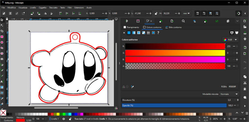
Key Features for Laser Cutting:
- SVG File Creation: Inkscape specializes in creating and editing SVG files, the preferred format for K40 Whisperer, ensuring smooth compatibility.
- Layer Management: Organizing different parts of your design into layers within Inkscape allows for more controlled and efficient cutting and engraving processes.
- Path Operations: Complex designs can be simplified into paths that are easily interpreted by laser cutting software, optimizing the machine’s motion and improving cut quality.
Usage in Laser Cutting: Before sending a design to the K40 Whisperer, it’s typically created or finalized in Inkscape. Users can adjust dimensions, define cutting lines, and convert images to vector paths, making Inkscape an indispensable tool for preparing laser-ready artwork.
You can download it from here.
K40 Whisperer
K40 Whisperer is a control software developed specifically for the K40 Laser Cutter to replace the less user-friendly stock software that comes with the machine. It’s known for its simplicity and effectiveness in managing the K40’s capabilities.

Key Features for Laser Operation:
- Direct Control: It directly interprets SVG files from Inkscape, handling both vector and raster data seamlessly.
- Layered Cutting and Engraving: Supports setting different power and speed settings for different layers defined in Inkscape, allowing intricate multi-layer operations.
- User Interface: Provides a straightforward, intuitive interface that displays the laser cutter’s bed and the positioning of the material.
Usage in Laser Cutting: K40 Whisperer acts as the interface between your design and the machine. After designing in Inkscape, users load their SVG files into K40 Whisperer to set up the laser operations, including cutting speed, power levels, and the sequence of cuts and engravings. The software also allows for real-time monitoring and adjustments during the cutting process.
You can download It from here.
Thanks
Upgrading a K40 CO2 laser with precision-focused enhancements like mirror alignment, air assist, laser diode crosshairs, and a real-time monitoring camera transforms this already capable machine into a more precise, efficient, and user-friendly tool. These modifications are particularly useful for anyone looking to achieve professional-grade results in a home or small business setting. By investing time and resources into these upgrades, users can significantly expand the capabilities of their K40 laser cutter, making it a formidable tool in their creative or manufacturing endeavors.
- K40 40w CO2 Laser cutter engraver: review, first usage, and upgrades (all you need to know)
- Using Inkscape and K40 Whisperer for Cutting and Engraving with a K40 CO2 Laser
- Enhance Your K40 CO2 Laser: 3d printed nozzle head with air assist and laser crosshairs
- Enhance Your K40 CO2 Laser: ESP32-CAM with 3D printed case to monitor your device


