Home › Forums › The libraries hosted on the site › EByte LoRa e220 UART devices LLCC68 › E220 using ESP8266
- This topic has 8 replies, 2 voices, and was last updated 3 years, 6 months ago by
Renzo Mischianti.
-
AuthorPosts
-
-
20 June 2022 at 02:34 #21451
Hello all,
i’m trying to use my Ebyte modules but i can’t even get the module information. I think it’s probably the pinout for my MCU. I’m following the configuration article and based on the schematic of ESP32 I wired up my NodeMCU.
But on the sketch, the pins passed to library constructor are confusing me a little.
// ---------- esp32 pins --------------
// LoRa_E220 e220ttl(&Serial2, 15, 21, 19); //  RX AUX M0 M1
Because I put the M0 and M1 on 3.3 V, RX -> TX, TX -> RX and don’t connected AUX. Like in the image below:
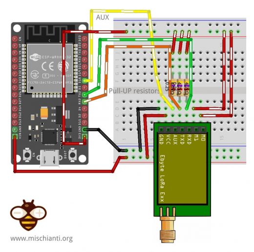
What can I been doing wrong? Thanks in advance.
-
20 June 2022 at 08:46 #21452
Hi warleysr,
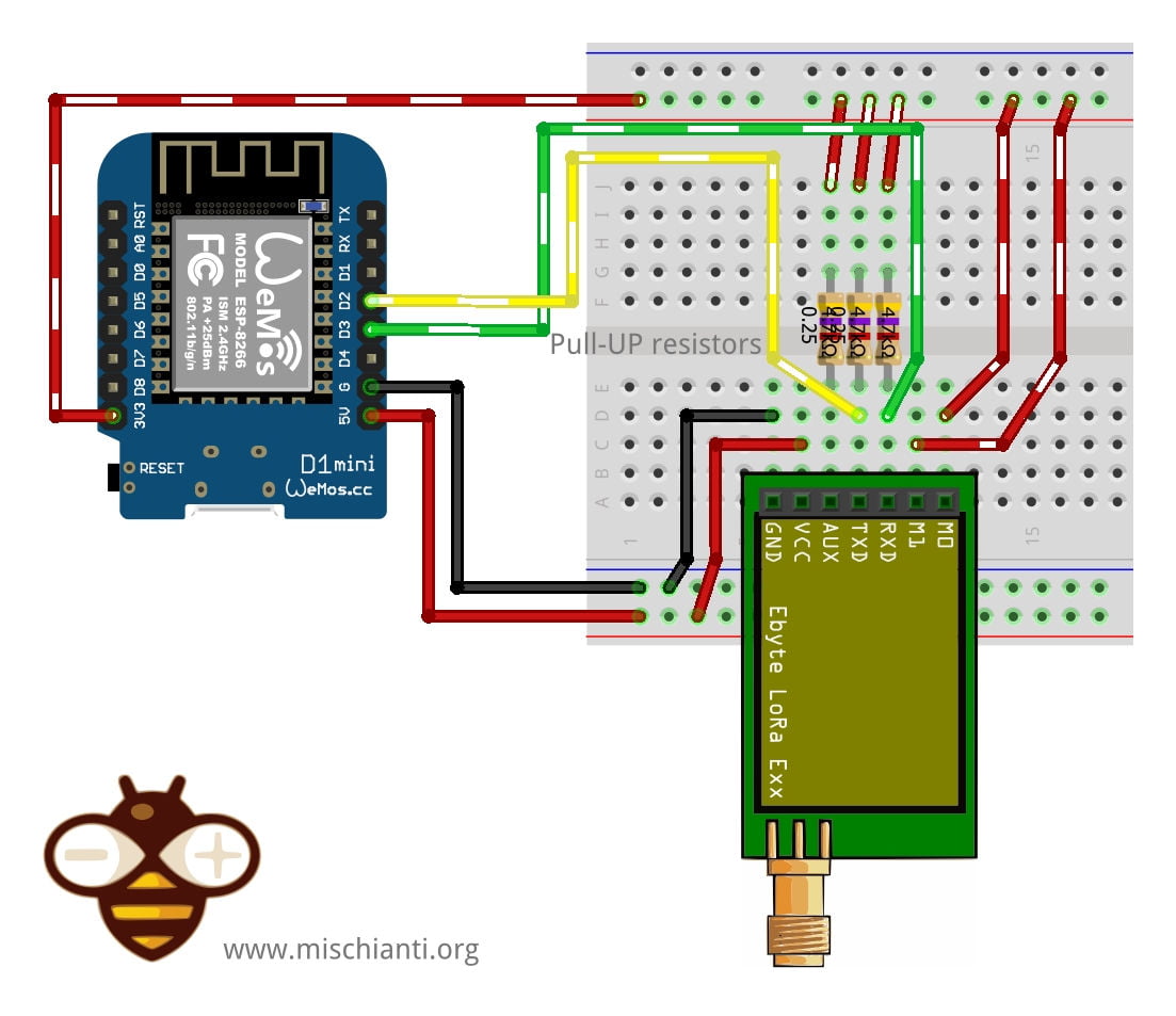
try to connect the AUX pin also to pin 15 and send the output of your program.f you don’t connect M0 and M1 remove it from the constructor.
LoRa_E220 e220ttl(&Serial2, 15);If you have a nodeMCU you must follow the schematic of esp8266.

M0	VCC (Set programming/sleep mode)
M1	VCC (Set programming/sleep mode)
TX	PIN D2 (PullUP 4,7KΩ)
RX	PIN D3 (PullUP 4,7KΩ)
AUX	Not connected better PIN D5 (PullUP 4,7KΩ)
VCC	5v
GND	GND
LoRa_E220 e220ttl(D2, D3, D5); // Arduino RX <-- e220 TX, Arduino TX --> e220 RX AUX M0 M1Bye Renzo
-
13 July 2022 at 21:01 #21867
Hi, Renzo,
I tried to follow your instructions but I still can’t get the module info. Actually, my microcontroller is a LoLin NodeMCU with this pinout:

I’m getting only strangers characters on Serial Monitor. Sorry for delayed response btw.
-
14 July 2022 at 08:20 #21875
Hi Warleysr,
use the connection schema linked here and enable debug by uncomment the debug define, connect also the AUX pin to D5 and send me the output.
Bye Renzo -
16 July 2022 at 00:07 #21882
Hi Renzo,
I followed your instructions and this is what I got:
The M0 and M1 pins is not set, this mean that you are connect directly the pins as you need!
AUX HIGH!
Complete!
3
Available buffer: 10 structure size: 11
----------------------------------------
HEAD : 0 17 3

AddH : 0
AddL : 0

Chan : 3 -> 413MHz

SpeedParityBit     : 0 -> 8N1 (Default)
SpeedUARTDatte     : 110 -> 57600bps
SpeedAirDataRate   : 1 -> 2.4kbps

OptionSubPacketSett: 0 -> 200bytes (default)
OptionTranPower    : 0 -> 22dBm (Default)
OptionRSSIAmbientNo: 0 -> Disabled (default)

TransModeWORPeriod : 0 -> 500ms
TransModeEnableLBT : 0 -> Disabled (default)
TransModeEnableRSSI: 0 -> Disabled (default)
TransModeFixedTrans: 0 -> Transparent transmission (default)
----------------------------------------
The M0 and M1 pins is not set, this mean that you are connect directly the pins as you need!
AUX HIGH!
Complete!
Data size not match!
7
----------------------------------------
HEAD : 0 17 3

AddH : 0
AddL : 0

Chan : 3 -> 413MHz

SpeedParityBit     : 0 -> 8N1 (Default)
SpeedUARTDatte     : 110 -> 57600bps
SpeedAirDataRate   : 1 -> 2.4kbps

OptionSubPacketSett: 0 -> 200bytes (default)
OptionTranPower    : 0 -> 22dBm (Default)
OptionRSSIAmbientNo: 0 -> Disabled (default)

TransModeWORPeriod : 0 -> 500ms
TransModeEnableLBT : 0 -> Disabled (default)
TransModeEnableRSSI: 0 -> Disabled (default)
TransModeFixedTrans: 0 -> Transparent transmission (default)
----------------------------------------
The M0 and M1 pins is not set, this mean that you are connect directly the pins as you need!
AUX HIGH!
Complete!
3
Available buffer: 6 structure size: 6
AUX HIGH!
Complete!
The M0 and M1 pins is not set, this mean that you are connect directly the pins as you need!
AUX HIGH!
Complete!
----------------------------------------
HEAD: 10110 193 0
Model no.: 8
Version  : 0
Features : 0
Status : Save mode returned not recognized!
----------------------------------------
Save mode returned not recognized!
11
----------------------------------------
HEAD: 16 C1 0
Model no.: 8
Version  : 0
Features : 0
----------------------------------------
When I connected on RX/TX named pins (D9 and D10) I got the strangers characters.
-
18 July 2022 at 08:05 #21890
Hi warleysr,
a similar problem also here (resolved with the properly use of library).Try to add an external power supply and check if M0 and M1 go HIGH correctly.
Bye Renzo
-
18 July 2022 at 21:18 #21897
Hi Renzo,
I checked the pins with the voltimeter and all except the GND have a p.d. of 3.3 V. I defined the ACTIVATE_SOFTWARE_SERIAL variable on LoRa_E220.h file but I started to got this error on Serial Monitor:
The M0 and M1 pins is not set, this mean that you are connect directly the pins as you need!
Timeout error!

Exception (28):
epc1=0x4000df7c epc2=0x00000000 epc3=0x00000000 excvaddr=0x00000000 depc=0x00000000

>>>stack>>>

ctx: cont
sp: 3ffffdc0 end: 3fffffc0 offset: 01a0
3fffff60:  feefeffe feefeffe feefeffe feefeffe
3fffff70:  feefeffe feefeffe feefeffe feefeffe
3fffff80:  00000000 00000924 feefef00 feefeffe
3fffff90:  feefeffe feefeffe feefeffe 3ffee5c4
3fffffa0:  3fffdad0 00000000 3ffee584 40204358
3fffffb0:  feefeffe feefeffe 3ffe84e4 4010120d
<<<stack<<<
⸮⸮
Connect the cables again!
RX MIC ---> 4
TX MIC ---> 0
AUX ---> 14
M0 ---> -1
M1 ---> -1
Init AUX pin!
Begin ex
Begin Software Serial
Begin
The M0 and M1 pins is not set, this mean that you are connect directly the pins as you need!
Timeout error!
The error persisted for some time, and stopped occasionally. The only difference between my physical circuit and the schematic is that I’m using 10k ohms resistors. Can it produce this behavior?
-
20 July 2022 at 08:31 #21925
Hi Warleysr,
I don’t know because you have this behavior.
Try to remove completely the resistor.
Bye Renzo
-
-
AuthorPosts

- You must be logged in to reply to this topic.