Home › Forums › The libraries hosted on the site › EByte LoRa e32 UART devices sx1262/sx1268 › E32-900T20D Lora repeater settings
Tagged: E32-900T20D
- This topic has 11 replies, 2 voices, and was last updated 1 year ago by
g0730n.
-
AuthorPosts
-
-
21 January 2024 at 01:58 #29311
I am making a low power repeater using a 3.3v arduino and E32-900T20D module.
All I want repeater to do is receive any sent message, then resend it. I will have this device with bigger antenna mounted on roof for maximum line of sight.
What is best setting for this use case? Fixed or transparent?
I don’t quite understand the high and low address bits… do they need to be set when using transparent?
Thanks! The libraries provided have been very helpful for interfacing these modules. I am successfully able to send and receive messages between pi pico with micropython module and ATMEGA328P with arduino library.
Attachments:
You must be logged in to view attached files. -
22 January 2024 at 08:24 #29316
Hi g0730n,
you must create a repeater specified for your kind of network.If you create a transparent transmission network, you must use a transparent transmission and set the devices on the same ADDH ADDL and CHAN, but every time you repeat a message also, the sender receives It.
Ebyte LoRa E32 device for Arduino, esp32 or esp8266: fixed transmission – 4
For the fixed transmission you must create/manage a protocol or similar.
For example, you want to repeat a message that all devices must read: you must send the message to the repeater, and the repeater sends a broadcast message.If you want to send a message to a specified device, you must send the message to the repeater (or broadcast), and the repeater reads some information inside and sends a specified message.
There isn’t a specified solution.
For example, E22 has the repeater function, but It’s quite complex; here is a schema.
[caption id="attachment_21940" align="alignnone" width="300"]
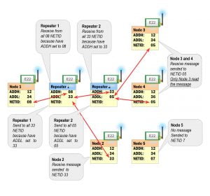 EByte LoRa E22 repeater mode schema[/caption]
I’d also like to ask you if you have some problems with the interoperation of MicroPyton and Arduino env because @Woto opened a topic on this forum with some encoding communication problem that I can’t replicate, can you give some advise to he please.
E220 Receive-Intervall and MycroPython and Arduino Env communication
Thanks, Renzo
-
22 January 2024 at 21:45 #29350
My idea was the sender sends the message, if the repeater receives it, the repeater wakes up the radio module and arduino, reads the message, then it resends it.
The sender waits for 5 seconds after sending, and if it receives the same message back, it uses that as a confirmation that the message was received by repeater, if it doesn’t receive it back, option to resend.
I will look into fixed mode with addressing, could be cool if multiple devices can use repeater to direct messages to devices with seperate channels or addresses, and have confirmation end node received message.
I have had some issues getting arduino to talk to pico, with some “unicode” errors and such… but I think I have narrowed it down to timing issues. My case is different than linked thread as my repeater microcontroller and e32 module are both sleeping, so I had to add calculated delays to sender and repeater to make sure there were no conflicts…
I will be playing around with settings more, as well as take a more in depth look at code from linked thread to see if I can figure out whats going on…
In linked thread, code is trying to send messages very frequently. To me this is not food practice for lora devices. And in some countries there are limits to the amount of data sent in a certain time period. In my opinion 1 message per 30 seconds sent from each device should be max. This also allows devices to time each other better and spend more time listening.
I have been using Pi Pico and Micropython for several years, but completely new to arduino and Arduino IDE. So learning as I go…
Attatched are photos of schematic and 3d view of PCB I am designing for low power Arduino repeater. I have tested this setup on breadboard and it works fine. The 3.3v LDO I am using can supply up to 250mA, and I have not had any issues with power using this LDO. I have put place for 100uF capacitor on PCB incase it’s needed.
On breadboard I am not using pullup resistor on TXD and RXD and it works fine. I did need to use pullup on AUX.
On Pi Pico, I needed pullups on TXD, RXD, and AUX. I believe Pico’s internal pullup is much higher value than ATMEGA328p… Unsure though.
I put optional pullup resistor spaces for all pins of E32, as well as I2C header for BME280 sensor (in case a different I2C sensor installed without pullup already.)
M0, and M1 do not need pullup correct? I am not using pullup on breadboard setup, but decided to put space for them on PCB in any case it’s ever needed.
PCB size was designed for this box: 115 x 90 x 55 mm I did not put any mounting screw holes, as the space inside the box is perfect fit. SMA connector will protrude into hole drilled in box, with o-ring and washer.
5v solar cell will be sealed to lid of box, and charge battery when sunny. a 200mA solar panel should keep LiPo charged as this device only uses <1mA when sleeping…
Attachments:
You must be logged in to view attached files. -
25 January 2024 at 09:46 #29370
Here is a 3d view and schematic of the Arduino repeater I am making. I appreciate any ideas. I was designing this to specifically fit inside this box:
https://www.amazon.com/dp/B092HS9CMR?th=1
Solar panel will be sealed to outside of box, and SMA connector will protrude through box, sealed with an o-ring.Code can be modified to use as a TEMP/PRESSURE/HUMIDITY sensor node, or connect any I2C or SPI sensor.
The PCB is exactly as I have it setup on breadboard. I put option for pullups on all lines to E32 module… I don’t think M0, and M1 need them, but there is a space there incase it ever did.
This device is ATMEGA328p running at 8mhz on internal oscillator, 3.3v. The HT7333 LDO seems to have no trouble at all powering LORA module and arduino IC. It can supply up to 250mA. On breadboard I have used it without the 100uf capacitor shown in schematic. I added that to be optionally put in if needed.
What is interesting… on arduino setup I have, 3.3v, pi pico setup, also all 3.3v. Pi pico needs pullups on TXD, RXD, and AUX. Or it will not work.
Arduino setup, only pullup on AUX works, TXD, and RXD not needed. Any reason why? Does arduino chip have lower value internal pullup resistor than pico? I think pico internal pullup is 70k…
Attachments:
You must be logged in to view attached files. -
25 January 2024 at 09:47 #29376
Here is the updated PCB design, designed to fit in this box: https://www.amazon.com/dp/B083H9FNRT
This design is a larger sized PCB, with mounting holes for the board. I figured the mounting holes, especially if the box provides is a better idea.
Schematic is the same.
Attachments:
You must be logged in to view attached files. -
25 January 2024 at 09:50 #29406
Hi g,
The idea is very interesting; It can be useful.
no, M0 and M1 do not need pull-up, but have you resolved the Unicode problem?
Bye Renzo-
31 March 2024 at 22:33 #30233
I have not had the chance to experiment further. I am still waiting for my PCB from JLPCB, they were supposed to arrive several months ago but have not.
The breadboard setup i had going I have since disassembled and using breadboards for other projects.
Am in process of contacting shipping companies to track PCB down.
This is my 4th order with JLPCB and all previous orders were manufactured and shipped quickly so not sure what happened with this one.
-
-
30 June 2024 at 21:27 #30877
I have FINALLY received the PCB’s for this project. The first order was indeed lost. JLCPCB gave me a coupon, so basically was able to reorder and only pay $2 for shipping. New shipment came in quick like the service I usually received from them.
So far I have assembled everything on one PCB except the LORA module. I wanted to make sure everything else worked first before soldering that on as it is a more expensive component for this project.
Everything works great. Battery Charge and LDO are working flawlessly. The header breakout and reset button also work. Next I will solder on LORA module and test with that.
The difference is I am using a E22-900T22S module. Which is different from the E32 I was using before. I will update progress with this device.
I call it a “Repeater” but it could function in many ways.
- Battery Powered Arduino
- Battery Powered Arduino with sensors
- Solar/Battery Powered Arduino
- Arduino sensor/ Lora node.
- Lora repeater.
The main idea is it’s in a sealed weatherproof box, powered by a small solar panel. I have tested the same size panel and charge module for over a year and have been able to power a low powered device consistently. Where I live, there is little sun 6 months out of the year, yet the device was able to keep running.
The box I tested in elements with tissue paper in for 4 months. When I checked it, it was still dry. The box had been in rain/ice/snow.
My idea is to mount one of these in a tall tree nearby with a good antenna, and see what sort of range I can get.
-
1 July 2024 at 12:48 #30878
Hi g,
remember that the power supply and antenna are crucial for the range of transmission; put also a good capacitor on the battery to supply sufficient peak current.
Bye Renzo -
16 December 2024 at 12:05 #31938
Oof…
Finally got around to this project some more. It is all assembled I just need to pop in the BME280 sensor.
I spent several hours trying to get it to talk to my E32 modules, before finally reading some more that these will not talk to E32’s haha! Oh well, I will just have to assemble another one to fully test it.
Everything else on the board is working great, and I am able to set the configuration for the module, but as the E22 modules I have are all SMD like this one, I cannot test transmission until I assemble another board.
I have two e32 modules with pins on them, which I have played around with a bit. I will probably only use E22 now that I have built this device with the E22.
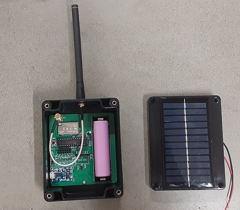
Attachments:
You must be logged in to view attached files. -
16 December 2024 at 12:14 #31941
Hi g,
Well done! The project looks clean and well-designed, with the PCB neatly housed in the box. The solar panel and antenna add a practical and professional touch. If you’d like to share it on the site, I’m happy to help!
Bye Renzo-
4 January 2025 at 08:49 #32016
Hey Renzo, I have too many projects going at once, so haven’t had much time to work on this but after I have done all tests and comfirmed everything is working right I will let you know and if you want to put it on site then thats great.
I got 2 more E22-900T22 devices so I can test with the module i installed on this board, but with the little time I had to work on it still didn’t get them to communicate. Will post when I do.
-
-
-
AuthorPosts
- You must be logged in to reply to this topic.