- This topic has 8 replies, 2 voices, and was last updated 3 years, 10 months ago by
Renzo Mischianti.
-
AuthorPosts
-
-
17 February 2022 at 17:19 #18757
Hello.
I am working on a personal project using the LoRa module E32-TTL-100.
My setup is composed of two Arduinos and two E32 modules. I am basically connecting each Arduino to each E32 module, and my aim is to successfully set a communication between these two pairs using LoRa.
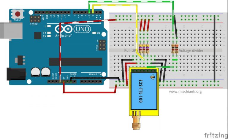
For the connection between Arduino and E32 I am using the following circuit.
For the code, I am using the one in Ebyte LoRa E32 device for Arduino, esp32 or esp8266: fixed transmission – 4.
/*
 * LoRa E32-TTL-100
 * Write on serial to transfer a message to other device
 * http://mischianti.org
 *
 * E32-TTL-100----- Arduino UNO
 * M0         ----- GND
 * M1         ----- GND
 * TX         ----- PIN 2 (PullUP)
 * RX         ----- PIN 3 (PullUP & Voltage divider)
 * AUX        ----- Not connected
 * VCC        ----- 3.3v/5v
 * GND        ----- GND
 *
 */
#include "Arduino.h"
#include "LoRa_E32.h"

LoRa_E32 e32ttl100(2, 3); // e32 TX e32 RX

void setup() {
  Serial.begin(9600);
  delay(500);

  Serial.println("Hi, I'm going to send message!");

  // Startup all pins and UART
  e32ttl100.begin();

  // Send message
  ResponseStatus rs = e32ttl100.sendMessage("Hello, world?");
  // Check If there is some problem of successfully send
  Serial.println(rs.getResponseDescription());
}

void loop() {
    // If something available
  if (e32ttl100.available()>1) {
      // read the String message
    ResponseContainer rc = e32ttl100.receiveMessage();
    // Is something goes wrong print error
    if (rc.status.code!=1){
        rc.status.getResponseDescription();
    }else{
        // Print the data received
        Serial.println(rc.data);
    }
  }
  if (Serial.available()) {
      String input = Serial.readString();
      e32ttl100.sendMessage(input);
  }
}
I have uploaded this same code to both Arduinos and then opened the Serial consoles to monitor if the communication was happening as expected. However, I only get the prints saying that the message was sent succesfully on the sender’s end, but never see the receiving end printing the received message.
Am I doing something wrong? I am totally new to LoRa, so I am also very lost in this and kinda burned out, since I’ve being trying to get it to work for days now.
I wonder if I am skipping some configuratin step I was supposed to be doing before this.
Thanks in advance for any help.
-
17 February 2022 at 17:24 #18764
Hi linx9,
to have more information attach also the AUX pin, which gives an immediate response on wiring.And get the configuration of the devices to be sure are correctly configured.
Post your response on this topic.
I wait for your feedback Renzo
-
17 February 2022 at 20:15 #18772
I decided to try switching to Sleep Mode and check what the Get Configuration code would output for each of my circuits.
Output for Arduino 1:
No response from device! (Check wiring)
12
----------------------------------------
HEAD BIN: 0 0 0

AddH BIN: 0
AddL BIN: 1100101
Chan BIN: 115 -> 525MHz

SpeedParityBit BIN    : 1 -> 8O1
SpeedUARTDataRate BIN : 110 -> 57600bps
SpeedAirDataRate BIN  : 11 -> 4.8kbps
OptionTrans BIN       : 0 -> Transparent transmission (default)
OptionPullup BIN      : 0 -> TXD, RXD, AUX are open-collectors
OptionWakeup BIN      : 0 -> 250ms (default)
OptionFEC BIN         : 0 -> Turn off Forward Error Correction Switch
OptionPower BIN       : 0 -> 20dBm (Default)
----------------------------------------
No response from device! (Check wiring)
12
----------------------------------------
HEAD BIN: 0 0 0
Freq.: 0
Version  : 64
Features : 42
----------------------------------------
Output for Arduino 2:
No response from device! (Check wiring)
12
----------------------------------------
HEAD BIN: 0 0 0

AddH BIN: 0
AddL BIN: 11000011
Chan BIN: 115 -> 525MHz

SpeedParityBit BIN    : 1 -> 8O1
SpeedUARTDataRate BIN : 110 -> 57600bps
SpeedAirDataRate BIN  : 11 -> 4.8kbps
OptionTrans BIN       : 0 -> Transparent transmission (default)
OptionPullup BIN      : 0 -> TXD, RXD, AUX are open-collectors
OptionWakeup BIN      : 0 -> 250ms (default)
OptionFEC BIN         : 0 -> Turn off Forward Error Correction Switch
OptionPower BIN       : 0 -> 20dBm (Default)
----------------------------------------
Success
1
----------------------------------------
HEAD BIN: 11000011 195 C3
Freq.: 32
Version  : 53
Features : 14
----------------------------------------
Does this give us any information on where there might be a problem?
Thanks for the help.
-
17 February 2022 at 21:08 #18779
Hi linx9,
the message is clearNo response from device! (Check wiring) 12there is a problem with the connection.
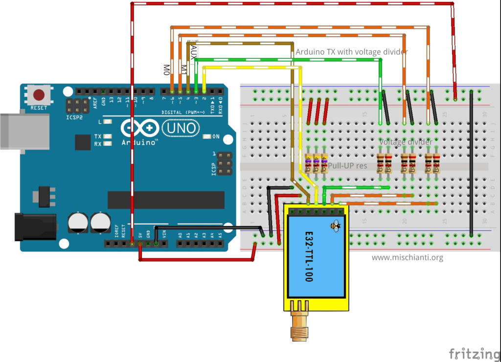
Connect AUX of e32 to pin 4 and change the constructor like so
LoRa_E32 e32ttl100(2, 3, 4); // e32 TX e32 RX AUXcheck your wiring, and try to remove the resistor if needed.
Bye Renzo
-
17 February 2022 at 21:35 #18782
Thanks for the help.
I have connected the AUX to pin 4 from Arduino. However I’m still getting the error message “No response from device! (Check wiring) 12”.
Which of the resistors in the circuit are you refering to?
Best,
Linx -
17 February 2022 at 22:18 #18783
The pull up resistor (the three closer).
Inside the Lora_e32.h you can also enabled the DEBUG by uncomment the relative define.
Bye Renzo
-
21 February 2022 at 12:53 #18821
Hello. Thanks a lot for the tips.
I have enabled the debugging mode and now I’m getting the following message in the serial monitor.
Init AUX pin!
Begin ex
Begin Software Serial
Begin
The M0 and M1 pins is not set, this mean that you are connect directly the pins as you need!
AUX HIGH!
Complete!
The M0 and M1 pins is not set, this mean that you are connect directly the pins as you need!
AUX HIGH!
Complete!
3
Available buffer: 0 structure size: 6
----------------------------------------
HEAD : 0 0 0

AddH : 0
AddL : 207
Chan : 239 -> 649MHz

SpeedParityBit     : 10 -> 8E1
SpeedUARTDatte  : 111 -> 115200bps
SpeedAirDataRate   : 110 -> 19.2kbps
OptionTrans        : 1 -> Fixed transmission (first three bytes can be used as high/low address and channel)
OptionPullup       : 1 -> TXD, RXD, AUX are push-pulls/pull-ups
OptionWakeup       : 111 -> 2000ms
OptionFEC          : 0 -> Turn off Forward Error Correction Switch
OptionPower        : 0 -> 20dBm (Default)
----------------------------------------
The M0 and M1 pins is not set, this mean that you are connect directly the pins as you need!
AUX HIGH!
Complete!
No response from device! (Check wiring)
12
----------------------------------------
HEAD BIN: 0 0 0

AddH BIN: 0
AddL BIN: 11001111
Chan BIN: 239 -> 649MHz

SpeedParityBit BIN    : 10 -> 8E1
SpeedUARTDataRate BIN : 111 -> 115200bps
SpeedAirDataRate BIN  : 110 -> 19.2kbps
OptionTrans BIN       : 1 -> Fixed transmission (first three bytes can be used as high/low address and channel)
OptionPullup BIN      : 1 -> TXD, RXD, AUX are push-pulls/pull-ups
OptionWakeup BIN      : 111 -> 2000ms
OptionFEC BIN         : 0 -> Turn off Forward Error Correction Switch
OptionPower BIN       : 0 -> 20dBm (Default)
----------------------------------------
The M0 and M1 pins is not set, this mean that you are connect directly the pins as you need!
AUX HIGH!
Complete!
3
Available buffer: 4 structure size: 4
AUX HIGH!
Complete!
The M0 and M1 pins is not set, this mean that you are connect directly the pins as you need!
AUX HIGH!
Complete!
----------------------------------------
HEAD BIN INSIDE: 11000011 195 C3
Freq.: 32
Version  : 53
Features : 14
----------------------------------------
Success
1
----------------------------------------
HEAD BIN: 11000011 195 C3
Freq.: 32
Version  : 53
Features : 14
----------------------------------------
I checked all wires multiples times with multimeter and have redone all wire connections. Do you have any insight on what may be going wrong?
Best,
Linx -
21 February 2022 at 13:19 #18822
I have realized that it was not working because I was not using the complete circuit.
Now I have built with the complete circuit (below), and stopped getting the error in the getConfiguration routine.
Now I will try to make a simple communication using the Part 1 tutorial and will report back with the results.
Thank you!
-
21 February 2022 at 14:01 #18823
Ahh! Perfect, tell me if you fix your problem.
Bye Renzo
-
-
AuthorPosts
- You must be logged in to reply to this topic.