Home › Forums › The libraries hosted on the site › PCF8575 16bits i2c digital I/O expander › PCF8575 on esp32
- This topic has 9 replies, 2 voices, and was last updated 2 years, 9 months ago by
Renzo Mischianti.
-
AuthorPosts
-
-
23 November 2021 at 07:11 #16494
 Zohair Hassan
Hi,,
I have been trying to use this library with esp32 but no luck so far.. All I want to do is toggle some relays connected on the extender IC but while running the IC doesn’t seem to respond..
The I2C scanner shows the address at 0x20.. and my SDA, SCL pins are connected to 21 and 22 respectively.. Not sure, what I am doing wrong.. code below..
#include "Arduino.h"
#include "PCF8575.h"// Set i2c address
PCF8575 pcf8575(0x20);void setup() {
Serial.begin(115200);
// Set pinMode to OUTPUT
for(int i=0;i<8;i++) {
pcf8575.pinMode(i, OUTPUT);
}
pcf8575.begin();
}void loop()
{
static int pin = 0;
pcf8575.digitalWrite(pin, HIGH);
Serial.println("ON");
delay(1000);
pcf8575.digitalWrite(pin, LOW);
Serial.println("OFF");
delay(1000);
pin++;
if (pin > 7) pin = 0;} -
23 November 2021 at 23:17 #16497
Hi Zohair,
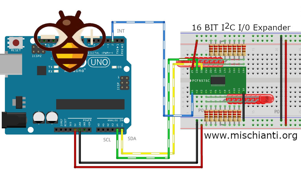
I do the test with the example sketch/* * PCF8575 GPIO Port Expand * Inverted led test: all led is connected with anodo to the IC * * PCF8575 ----- esp32 * GND ----- GND * VDD ----- 3.3V * SDA ----- 21 * SCL ----- 22 * * P0 ----------------- LED0 * P1 ----------------- LED1 * P2 ----------------- LED2 * P3 ----------------- LED3 * P4 ----------------- LED4 * P5 ----------------- LED5 * P6 ----------------- LED6 * P7 ----------------- LED7 * P8 ----------------- LED8 * P9 ----------------- LED9 * P10 ----------------- LED10 * P11 ----------------- LED11 * P12 ----------------- LED12 * P13 ----------------- LED13 * P14 ----------------- LED14 * P15 ----------------- LED15 * */ #include "Arduino.h" #include "PCF8575.h" // https://github.com/xreef/PCF8575_library // Set i2c address PCF8575 pcf8575(0x20); void setup() { Serial.begin(9600); // Set pinMode to OUTPUT for(int i=0;i<16;i++) { pcf8575.pinMode(i, OUTPUT); } for(int i=0;i<16;i++) { pcf8575.digitalWrite(i, HIGH); } pcf8575.begin(); } void loop() { static int pin = 0; Serial.print("SET LOW "); Serial.println(pin); pcf8575.digitalWrite(pin, LOW); Serial.print("READ pin and pin5 "); Serial.print(pcf8575.digitalRead(pin)); Serial.print(" - "); Serial.println(pcf8575.digitalRead(P5)); delay(1000); Serial.print("SET HIGH "); Serial.println(pin); pcf8575.digitalWrite(pin, HIGH); delay(1000); pin++; if (pin > 15) pin = 0; }And all work ok, check the connection schema on the article
Remember that IT hasn’t enought power to light a led, so you must put the LED catodo on PCF and power with resistor on anodo.
Bye Renzo -
5 April 2023 at 10:02 #25107
Hello,
Not sure why but I have tried this library with a NodeMCU ESP32s and the PCF8575 module.Even the simple blink program does not work.
Followed
* PCF8575 —– esp32
* GND —– GND
* VCC —– 3.3V
* SDA —– 21
* SCL —– 22LED Cathode is connected to PCF8575 P0 and Anode is connected to
3.3 V of ESP32Is there something wrong with my setup?
-
5 April 2023 at 12:32 #25229
Hi Mark,
I retest the library again, and It’s working ok.Can you do an i2c scanner and paste the result here?
#include <Wire.h>

void setup()
{
  Wire.begin();

  Serial.begin(9600);
  Serial.println("\nI2C Scanner");
}

void loop()
{
  byte error, address;
  int nDevices;

  Serial.println("Scanning...");

  nDevices = 0;
  for(address = 1; address < 127; address++ )
  {
    // The i2c_scanner uses the return value of
    // the Write.endTransmisstion to see if
    // a device did acknowledge to the address.
    Wire.beginTransmission(address);
    error = Wire.endTransmission();

    if (error == 0)
    {
      Serial.print("I2C device found at address 0x");
      if (address<16)
        Serial.print("0");
      Serial.print(address,HEX);
      Serial.println("  !");

      nDevices++;
    }
    else if (error==4)
    {
      Serial.print("Unknow error at address 0x");
      if (address<16)
        Serial.print("0");
      Serial.println(address,HEX);
    }
  }
  if (nDevices == 0)
    Serial.println("No I2C devices found\n");
  else
    Serial.println("done\n");

  delay(5000);           // wait 5 seconds for next scan
}
you must have a this result
Scanning...
I2C device found at address 0x20  !
done

Scanning...
I2C device found at address 0x20  !
done

Scanning...
I2C device found at address 0x20  !
done
Bye Renzo
-
5 April 2023 at 13:08 #25230
I2C Scanner is okay though as that is the first thing I have tested.
Scanning...
I2C device found at address 0x20!
done

Scanning...
I2C device found at address 0x20!
done
But the LED does not blink. I changed the pins to the different output ports of PFC8575 but I am not successful as well.
#include "Arduino.h"
#include "PCF8575.h"

// Set i2c address
PCF8575 pcf8575(0x20);

const int PIN = P7;
void setup()
{
  Serial.begin(9600);

  // Set pinMode to OUTPUT
  pcf8575.pinMode(PIN, OUTPUT);
  pcf8575.begin();
  pcf8575.digitalWrite(PIN, HIGH);
}

void loop()
{
  Serial.println("HIGH");
  pcf8575.digitalWrite(PIN, LOW);
  delay(2000);
  Serial.println("LOW");
  pcf8575.digitalWrite(PIN, HIGH);
  delay(2000);
}
In this video of yours, I notice a resistor there where is it connected? https://www.youtube.com/watch?v=jWeHzBLeN6s
-
5 April 2023 at 15:39 #25234
Tried it on both my 30 pins and 38 pins ESP32.
They both detected the I2C device at the default address of 0x20 but even the basic blink led of this library does not work.
I have tried switching the connection of the P0 on the PCF from anode to cathode but it does not work also.
If the anode is connected to P0 and the cathode is to ground, the LED lights up but it does not blink.
If the cathode is connected to P0 and the anode is to 3.3V, the LED does not light up.I tried connecting a normal I2C LCD to the SCL/SDA pins and it was successful.
Not sure what is missing but maybe some compatibility problem with my ESP32.
The original poster of this post has the same issue. I guess I am encountering the same.
-
5 April 2023 at 22:24 #25235
Hi,
It’s improbably that there is a compatibility problem, I think there is a mistake on the wiring or power supply to the LEDs.
Bye Renzo -
6 April 2023 at 01:00 #25236
Hi,
Can you tell me what is the mistake on the wiring or power supply to the LEDs?The README.MD files of your library and on your site are different also so what is the correct wiring?
Also, this is my ESP32 board that I have purchased https://www.aliexpress.com/item/1005004180608116.html
Maybe the original poster and I have the same board.
Thanks and more power!
-
6 April 2023 at 07:30 #25237
Hi mark,
I replicate the test with an esp32 dev kit v1 and a pcf8575 with 16 led, and It’s work without a problem, so if I can’t replicate your problem, I can only do some supposition to try to help.For the scheme follow the site.
Bye Renzo -
8 April 2023 at 12:58 #25238
Hello
Hey,
Let me try with a devkit, may I know if the wiring you are saying is the link above?
Cathode is connected to the P0-P17 of the PCF8575 and the anode is connected to the Arduino pins.Which is quite different from the GitHub page image
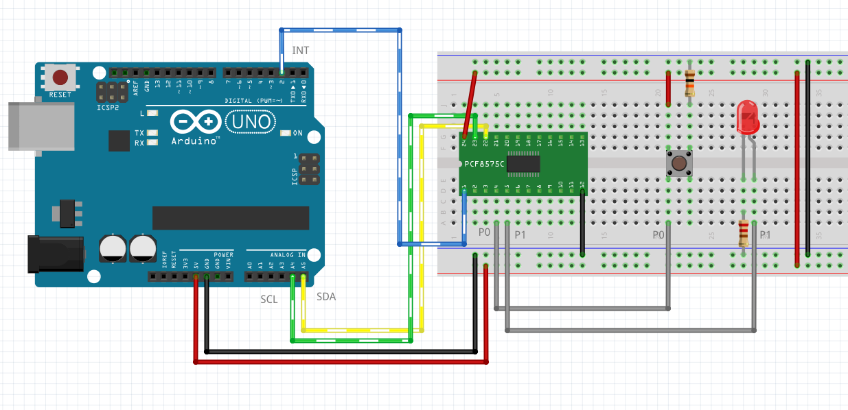
I am using the module type and not the IC Type so there is no other external connection like a resistor because your YouTube video has a resistor connected to some pins.
* PCF8575 —– esp32
* GND —– GND
* VCC —– 3.3V
* SDA —– 21
* SCL —– 22Thank you!
-
10 April 2023 at 08:48 #25280
Hi Mark,
refer to the article, the documentation that is maintained is that.
PCF8575 i2c 16 bit digital I/O expanderThe pcf8575 doesn’t have sufficient power to light 5mm led, use It to put GND to the Catode.
Bye Renzo
-
-
AuthorPosts
- You must be logged in to reply to this topic.