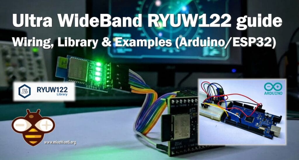
Precision Indoor Positioning with Ultra WideBand UWB, ESP32 & Arduino: Hardware & Basics
In the landscape of wireless communication, we are accustomed to Bluetooth and WiFi. While excellent for data transfer, they often struggle when it comes to precise distance measurement. RSSI (Received Signal Strength Indicator) fluctuates wildly due to obstacles and interference, making it unreliable for accurate localization.
I try to do this video, it isn’t my world, so be patient and give me suggestions. Thanks
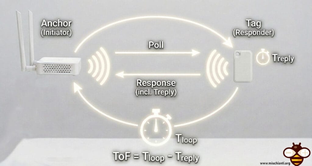
This is where Ultra-Wideband (UWB) technology steps in. Unlike narrowband signals, UWB transmits data across a very wide frequency spectrum using ultra-short pulses (nanoseconds). This physical characteristic allows for Time-of-Flight (ToF) measurement: calculating distance based on the exact time it takes for a radio wave to travel from the transmitter to the receiver. The result? Centimeter-level accuracy.
| Feature | UWB | Bluetooth | Wi-Fi | RFID | GPS |
| Where Used | Outdoor / Indoor | Outdoor / Indoor | Outdoor / Indoor | Outdoor / Indoor | Outdoor |
| Accuracy | Centimeter | 1-5 meters | 5-15 meters | Centimeter to 1 meter | 5-20 meters |
| Reliability | ⭐⭐⭐⭐⭐ Strong immunity to multi-path and interference | ⭐⭐ Very sensitive to multi-path, obstructions and interference | ⭐⭐ Very sensitive to multi-path, obstructions and interference | ⭐⭐⭐⭐ | ⭐⭐⭐ Very sensitive to obstructions |
| Range / Coverage | Typ. 70m (Max 250m) Typ. 250m² per anchor | Typ. 15m (Max 100m) Typ. 25m² per beacon (for 2m accuracy) | Typ. 50m (Max 150m) Typ. 100m² per access point (for 5m accuracy) | Typ. 1m (Max 5m) Typ. 25m² per reader | N/A |
| Data Communications | ✅ up to 27Mbps | ✅ up to 2Mbps | ✅ up to 1Gbps | ❌ | ❌ |
| Security (PHY Layer) | ⭐⭐⭐⭐⭐ Distance-Time bounded protocol | ⭐⭐ Can be spoofed using relay attack | ⭐⭐ Can be spoofed using relay attack | ⭐⭐ Can be spoofed using relay attack | N/A |
| Latency | ⭐⭐⭐⭐⭐ Typ. <1ms to get XYZ | ⭐⭐ Typ. >3s to get XYZ | ⭐⭐ Typ. >3s to get XYZ | ⭐⭐⭐ Typ. 1s to get XYZ | ⭐⭐ Typ. 100ms to get XYZ |
| Scalability Density | ⭐⭐⭐⭐ >10’s of thousands of tags | ⭐⭐⭐ Hundreds to a thousand tags | ⭐⭐ Hundreds to a thousand tags | ⭐⭐⭐⭐⭐ Unlimited | ⭐⭐⭐⭐⭐ Unlimited |
| Power & Battery | 5nJ/b TX · 9nJ/b RX (Coin Cell) | 15nJ/b RX/TX (Coin Cell) | 50nJ/b RX/TX (Lithium Battery) | Passive | Lithium Battery |
| Total Cost | $ | $ | $$$ | $$$ | $$$ |
The Reyax RYUW122 Module
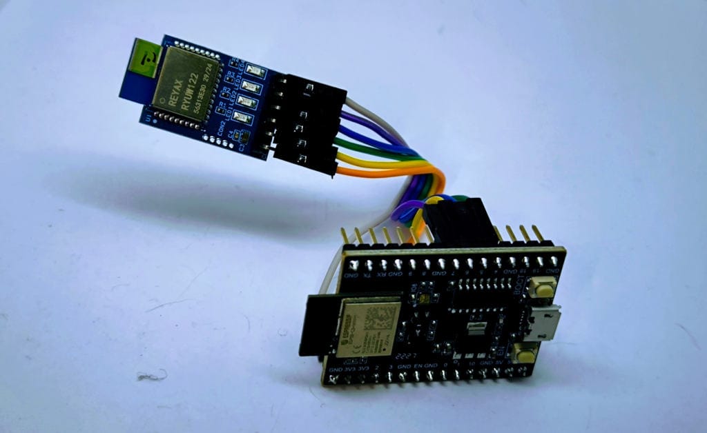
The Reyax RYUW122 is a compact UWB transceiver module compliant with IEEE 802.15.4z standards. It simplifies the complexity of RF design by integrating the antenna and the necessary firmware to handle ranging via simple UART (Serial) AT commands.
Here you can find the device RYUW122 Reyax distributor RYUW122_lite - Amazon RYUW122_lite - First Components RYUW122_lite
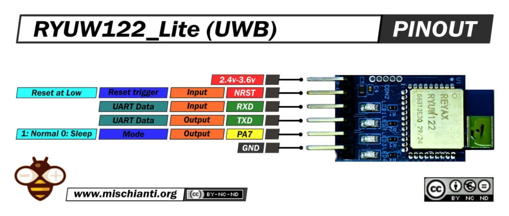
For makers and prototypers, the RYUW122_Lite breakout board is the best choice. It exposes the module’s pins to a standard 2.54mm header:
- VDD: 2.4V – 3.6V (Typically 3.3V)
- TXD/RXD: UART Interface
- NRST: Active Low Reset
- PA7: Mode Indicator (High = Active, Low = Sleep)
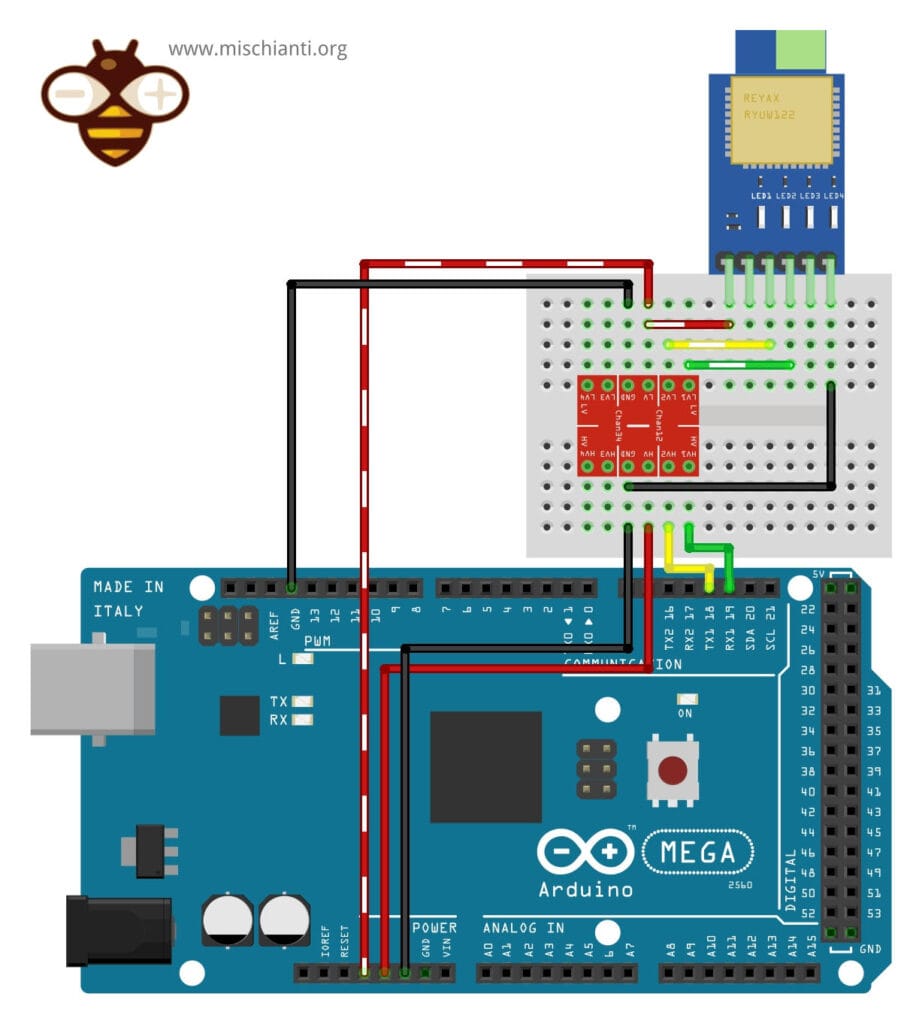
Wiring Guide: Arduino Mega
One critical detail must be addressed: The RYUW122 is a 3.3V device. Most classic Arduino boards (UNO, Nano, Mega) operate at 5V logic.
WARNING: Connecting the Arduino’s 5V TX pin directly to the RYUW122’s RXD pin will damage the module. You must use a Logic Level Converter or a Voltage Divider.
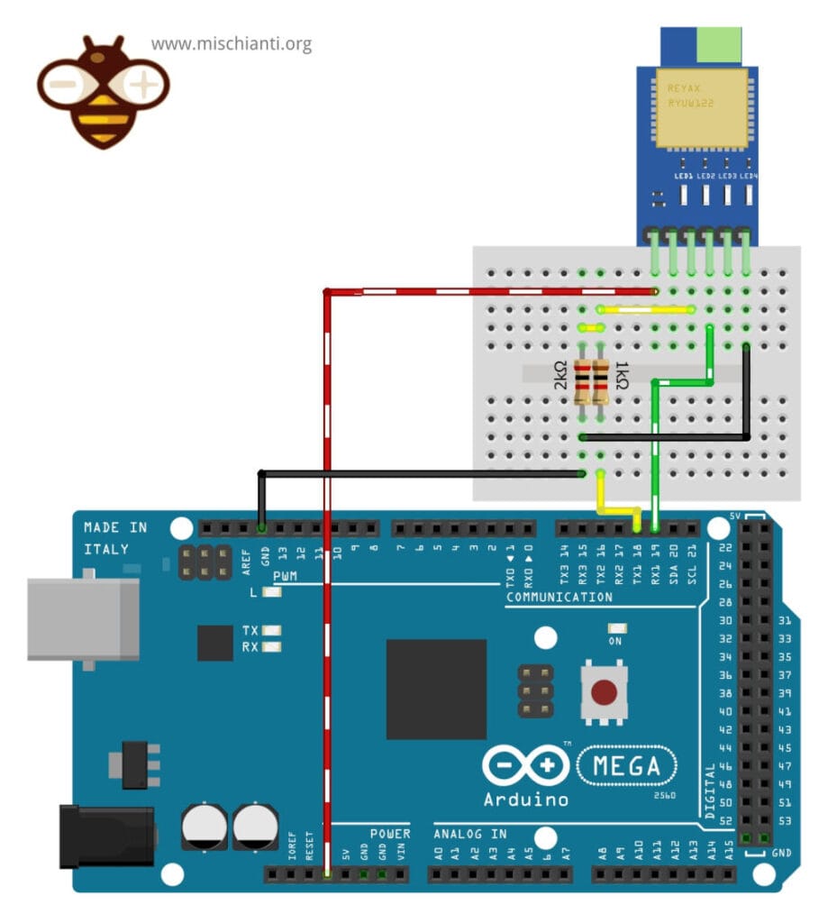
Wiring with Voltage Divider (The DIY Way)
We will use SoftwareSerial on the Arduino to communicate with the module. The voltage divider reduces the 5V signal from the Arduino to a safe 3.3V for the module.
Here you can find the Arduino Arduino UNO - Arduino MEGA 2560 R3 - Arduino Nano - Arduino Pro Mini
| Arduino Mega Pin | Voltage Divider / Connection | RYUW122 Lite Pin |
| 3.3V | Direct Wire | VDD |
| GND | Direct Wire | GND |
| RX1 (19) | Direct Wire (Green) | TX |
| TX1 (18) | 1kΩ Resistor (Series) & 2kΩ Resistor (to GND) | RX |
Wiring with Logic Level Converter (The Pro Way)
For a more robust connection, especially at higher baud rates, a bi-directional Logic Level Converter (LLC) is recommended.
| Arduino Mega Pins | Logic level converter | RYUW122 Lite Pin |
| 5V | HV | – |
| 3.3V | LV | VDD |
| GND | GND (both sides) | GND |
| TX1 (18) | HV1 | |
| RX1 (19) | HV2 | |
| LV1 | RX | |
| LV2 | TX |
RYUW122 uwb(&Serial1);
Important Notes
SoftwareSerial & Baud Rate: If you plan to use SoftwareSerial on Arduino UNO (or other AVR boards with only one hardware UART), note that SoftwareSerial is reliable only at low baud rates. Configure the RYUW122 module to 9600 baud before running sketches that use SoftwareSerial. You can do this by sending the AT command AT+IPR=9600 to the module while it is temporarily connected to a hardware serial at 115200 or the current baudrate. Failing to match a stable baud rate will result in lost or corrupted data.
Reset (NRST) pin: On ESP32 platforms the hardware reset pin (NRST) is often required to reliably initialize the RYUW122 module during startup. If you notice inconsistent behavior or missing responses, wire NRST to a GPIO and perform a hardware reset sequence during boot.
Voltage and Levels: The module is strictly 3.3V (not 5V tolerant). To use with 5V boards you need a logic level converter or a voltage divider. For further reading see the articles on mischianti.org about level shifting and safe wiring.
Wiring guide: ESP32
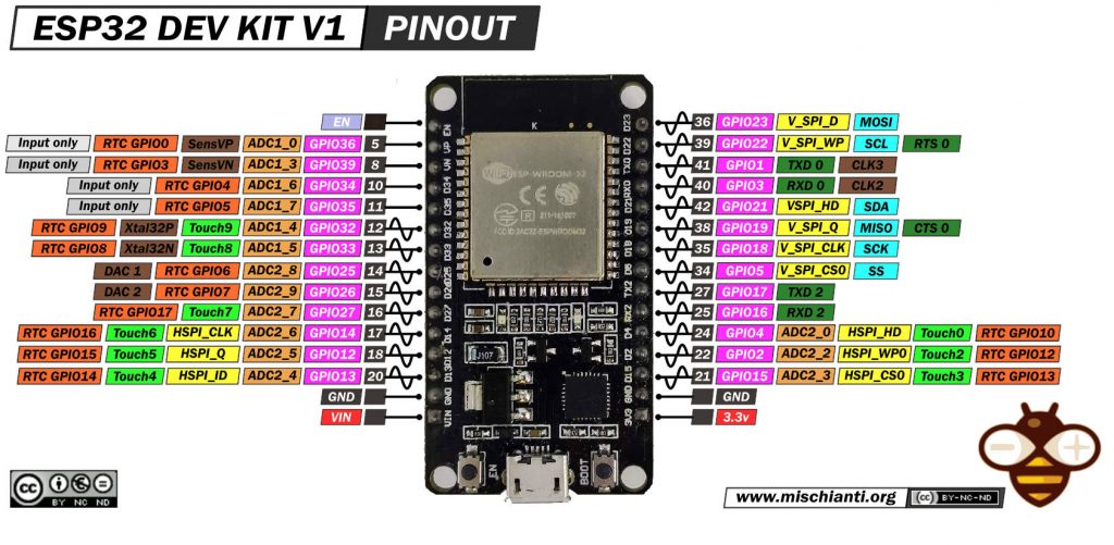
Here you can find my selection of esp32 ESP32 Dev Kit v1 - TTGO T-Display 1.14 ESP32 - NodeMCU V3 V2 ESP8266 Lolin32 - NodeMCU ESP-32S - WeMos Lolin32 - WeMos Lolin32 mini - ESP32-CAM programmer - ESP32-CAM bundle - ESP32-WROOM-32 - ESP32-S - ESP32-WROOM-32 - ESP32 2.8 Inch Touch ESP32-2432S028
The connection of ESP32 devices (or other 3.3v devices) It’s very simple.
ESP32
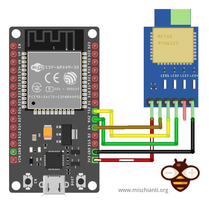
| ESP32 Pin | RYUW122 Lite Pin | Description |
| 3V3 | VDD | Power Supply |
| GND | GND | Ground |
| RX2 (16) | TX | Data Receive |
| TX2 (17) | RX | Data Transmit |
| 4 | NRST | Reset device |
#define RX_PIN 16  // Connect to RYUW122 TX
#define TX_PIN 17  // Connect to RYUW122 RX
#define RESET_PIN 4 // Connect to RYUW122 NRST (active LOW)

RYUW122 uwb(TX_PIN, RX_PIN, &Serial1, RESET_PIN);

// RYUW122 uwb(&Serial2, RESET_PIN);
ESP32-C3
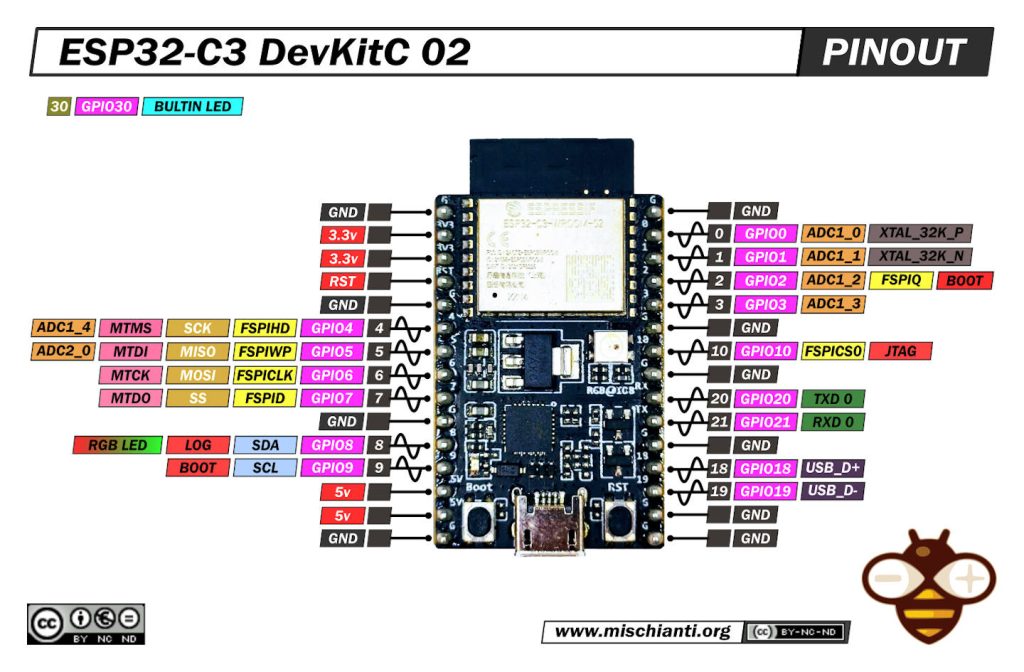
Here you can find my selection of esp32c3 LuatOS esp32c3 Core - ESP32-C3-DevKitC-02 - ESP32-C3-MINI-1 - WeMos LOLIN C3 PICO - WeMos LOLIN C3 Mini v2.1 - WeMos LOLIN C3 Mini v1.0 - ESP32 S3 Purlple AI-S3 - ESP32 C3 Zero - ESP32 C3 SuperMini
Now the wiring.

| ESP32-C3 Pin | RYUW122 Lite Pin |
| 3V3 | VDD |
| GND | GND |
| GPIO 5 (Green Wire) | RX |
| GPIO 4 (Yellow Wire) | TX |
| GPIO 6 (Blue Wire | NRST |
#define RX_PIN 5  // Connect to RYUW122 TX
#define TX_PIN 4  // Connect to RYUW122 RX
#define RESET_PIN 6 // Connect to RYUW122 NRST (active LOW)

RYUW122 uwb(TX_PIN, RX_PIN, &Serial1, RESET_PIN);
Library Installation
To abstract the complexity of AT commands, I have developed the RYUW122 Library. It handles parsing, timeouts, and asynchronous callbacks.
Arduino IDE
- Open the Arduino IDE.
- Go to Sketch -> Include Library -> Manage Libraries…
- Search for
RYUW122. - Click Install.

PlatformIO
Open your platformio.ini file and add the dependency:
lib_deps =
    xreef/RYUW122@^1.0.0
Device Communication Test (Setup)

This basic example demonstrates how to initialize the library, configure the module’s identity, and verify communication.
/*
 * Author: Renzo Mischianti
 * Website: https://mischianti.org
 * Copyright (c) 2025 Renzo Mischianti
 * Part of the RYUW122 Arduino library examples. See LICENSE for details.
 */

/**
 * @file device_communication_test.ino
 * @brief Basic example for testing RYUW122 module communication and configuration
 *
 * This example performs basic AT command tests to verify:
 * - Serial communication with the module
 * - Configuration of basic parameters
 * - Reading module information
 *
 * Hardware connections:
 * - RYUW122 TX  -> Arduino RX (e.g., Pin 10 for SoftwareSerial)
 * - RYUW122 RX  -> Arduino TX (e.g., Pin 11 for SoftwareSerial)
 * - RYUW122 GND -> Arduino GND
 * - RYUW122 VCC -> Arduino 3.3V or 5V (check module specifications)
 * For esp32 like device It's important to set also NRST
 * - RYUW122 NRST-> ESP32 GPIO for RESET
 *
 * Open the Serial Monitor at 115200 baud to see the test results.
 */

#include <RYUW122.h>


// ------------------ ARDUINO UNO SOFTWARE SERIAL ------------------
// Define pins for SoftwareSerial (adjust based on your board)
// #define RX_PIN 10  // Connect to RYUW122 TX
// #define TX_PIN 11  // Connect to RYUW122 RX
//
// // Create RYUW122 instance with SoftwareSerial for Arduino UNO
// RYUW122 uwb(TX_PIN, RX_PIN, RYUW122BaudRate::B_9600);
// -----------------------------------------------------------------
// -------------------------- ARDUINO MEGA -------------------------
// RYUW122 uwb(&Serial1);
// -----------------------------------------------------------------
// ------------------------ ESP32 ----------------------------------
#define RX_PIN 5  // Connect to RYUW122 TX
#define TX_PIN 4  // Connect to RYUW122 RX
#define RESET_PIN 6 // Connect to RYUW122 NRST (active LOW)

RYUW122 uwb( TX_PIN, RX_PIN, &Serial1, RESET_PIN);
// -----------------------------------------------------------------

void printTestResult(const char* testName, bool result) {
    Serial.print(F("["));
    Serial.print(result ? F("PASS") : F("FAIL"));
    Serial.print(F("] "));
    Serial.println(testName);
}

void printSeparator() {
    Serial.println(F("========================================"));
}

void setup() {
    // Initialize serial for debugging
    Serial.begin(115200);
    while (!Serial) {
        ; // Wait for serial port to connect (needed for native USB)
    }

    delay(1000); // Give time for module to power up

    Serial.println(F("\n"));
    printSeparator();
    Serial.println(F("RYUW122 Basic Test"));
    printSeparator();

    // Test 1: Initialize module
    Serial.println(F("\nTest 1: Initialize Module"));
    bool initResult = uwb.begin();
    printTestResult("Module Initialization", initResult);
    if (!initResult) {
        Serial.println(F("ERROR: Cannot initialize module!"));
        Serial.println(F("Check connections and baud rate."));
        while (1) {
            delay(1000);
        }
    }

    delay(500);

    // Test 2: AT command test
    Serial.println(F("\nTest 2: AT Command Communication"));
    bool atResult = uwb.test();
    printTestResult("AT Command Test", atResult);
    if (!atResult) {
        Serial.println(F("ERROR: Module not responding to AT commands!"));
        while (1) {
            delay(1000);
        }
    }

    delay(500);

    // Test 3: Get firmware version
    Serial.println(F("\nTest 3: Read Firmware Version"));
    char version[32];
    bool versionResult = uwb.getFirmwareVersion(version);
    printTestResult("Get Firmware Version", versionResult);
    if (versionResult) {
        Serial.print(F("  Version: "));
        Serial.println(version);
    }

    delay(500);

    // Test 4: Get unique ID
    Serial.println(F("\nTest 4: Read Unique ID"));
    char uid[32];
    bool uidResult = uwb.getUid(uid);
    printTestResult("Get Unique ID", uidResult);
    if (uidResult) {
        Serial.print(F("  UID: "));
        Serial.println(uid);
    }

    delay(500);

    // Test 5: Set and verify mode
    Serial.println(F("\nTest 5: Set Operating Mode (TAG)"));
    bool setModeResult = uwb.setMode(RYUW122Mode::TAG);
    printTestResult("Set Mode", setModeResult);

    RYUW122Mode currentMode = uwb.getMode();
    bool verifyModeResult = (currentMode == RYUW122Mode::TAG);
    printTestResult("Verify Mode", verifyModeResult);
    if (verifyModeResult) {
        Serial.print(F("  Current Mode: "));
        Serial.println(RYUW122Mode_description(currentMode));
    }

    delay(500);

    // Test 6: Set and verify baud rate
    Serial.println(F("\nTest 6: Verify Baud Rate"));
    RYUW122BaudRate currentBaud = uwb.getBaudRate();
    Serial.print(F("  Current Baud Rate: "));
    Serial.println(RYUW122BaudRate_description(currentBaud));

    delay(500);

    // Test 7: Set and verify RF channel
    Serial.println(F("\nTest 7: Set RF Channel"));
    bool setChannelResult = uwb.setRfChannel(RYUW122RFChannel::CH_5);
    printTestResult("Set RF Channel", setChannelResult);

    RYUW122RFChannel currentChannel = uwb.getRfChannel();
    bool verifyChannelResult = (currentChannel == RYUW122RFChannel::CH_5);
    printTestResult("Verify RF Channel", verifyChannelResult);
    if (verifyChannelResult) {
        Serial.print(F("  Current Channel: "));
        Serial.println(RYUW122RFChannel_description(currentChannel));
    }

    delay(500);

    // Test 8: Set and verify bandwidth
    Serial.println(F("\nTest 8: Set Bandwidth"));
    bool setBandwidthResult = uwb.setBandwidth(RYUW122Bandwidth::BW_850K);
    printTestResult("Set Bandwidth", setBandwidthResult);

    RYUW122Bandwidth currentBandwidth = uwb.getBandwidth();
    bool verifyBandwidthResult = (currentBandwidth == RYUW122Bandwidth::BW_850K);
    printTestResult("Verify Bandwidth", verifyBandwidthResult);
    if (verifyBandwidthResult) {
        Serial.print(F("  Current Bandwidth: "));
        Serial.println(RYUW122Bandwidth_description(currentBandwidth));
    }

    delay(500);

    // Test 9: Set and verify network ID
    Serial.println(F("\nTest 9: Set Network ID"));
    const char* testNetworkId = "REYAX123";
    bool setNetworkResult = uwb.setNetworkId(testNetworkId);
    printTestResult("Set Network ID", setNetworkResult);

    char currentNetworkId[16];
    bool getNetworkResult = uwb.getNetworkId(currentNetworkId);
    printTestResult("Get Network ID", getNetworkResult);
    if (getNetworkResult) {
        Serial.print(F("  Network ID: "));
        Serial.println(currentNetworkId);
    }

    delay(500);

    // Test 10: Set and verify address
    Serial.println(F("\nTest 10: Set Address"));
    const char* testAddress = "TEST1234";
    bool setAddressResult = uwb.setAddress(testAddress);
    printTestResult("Set Address", setAddressResult);

    char currentAddress[16];
    bool getAddressResult = uwb.getAddress(currentAddress);
    printTestResult("Get Address", getAddressResult);
    if (getAddressResult) {
        Serial.print(F("  Address: "));
        Serial.println(currentAddress);
    }

    delay(500);

    // Test 11: Set RF power
    Serial.println(F("\nTest 11: Set RF Power"));
    bool setPowerResult = uwb.setRfPower(RYUW122RFPower::N32dBm);
    printTestResult("Set RF Power", setPowerResult);

    RYUW122RFPower currentPower = uwb.getRfPower();
    bool verifyPowerResult = (currentPower == RYUW122RFPower::N32dBm);
    printTestResult("Verify RF Power", verifyPowerResult);
    if (verifyPowerResult) {
        Serial.print(F("  RF Power: "));
        Serial.println(RYUW122RFPower_description(currentPower));
    }

    delay(500);

    // Test 12: RSSI display setting
    Serial.println(F("\nTest 12: RSSI Display Setting"));
    bool setRssiResult = uwb.setRssiDisplay(RYUW122RSSI::ENABLE);
    printTestResult("Set RSSI Display", setRssiResult);

    RYUW122RSSI currentRssi = uwb.getRssiDisplay();
    bool verifyRssiResult = (currentRssi == RYUW122RSSI::ENABLE);
    printTestResult("Verify RSSI Display", verifyRssiResult);
    if (verifyRssiResult) {
        Serial.print(F("  RSSI Display: "));
        Serial.println(RYUW122RSSI_description(currentRssi));
    }

    delay(500);

    // Test 13: Distance calibration
    Serial.println(F("\nTest 13: Distance Calibration"));
    bool setCalResult = uwb.setDistanceCalibration(0);
    printTestResult("Set Calibration", setCalResult);

    int currentCal = uwb.getDistanceCalibration();
    Serial.print(F("  Calibration Value: "));
    Serial.print(currentCal);
    Serial.println(F(" cm"));

    delay(500);

    bool resetResult = uwb.factoryReset();
    Serial.print(F("Reset Result: "));
    Serial.println(resetResult ? F("Success") : F("Failed"));

    delay(500);

    // Summary
    printSeparator();
    Serial.println(F("Basic Test Complete!"));
    Serial.println(F("All essential functions tested."));
    printSeparator();
    Serial.println(F("\nModule is ready for operation."));
    Serial.println(F("Use RYUW122_Anchor_Example or RYUW122_Tag_Example"));
    Serial.println(F("for communication testing."));
}

void loop() {
    // Nothing to do in loop for basic test
    delay(1000);
}
The device_communication_test.ino example is the fundamental diagnostic sketch for the RYUW122 library. Its primary purpose is to act as a “sanity check” to verify that the physical wiring is correct and that the microcontroller can successfully communicate with the Reyax module via UART.
Unlike the operational examples (Tag/Anchor), this sketch does not attempt to communicate with other UWB devices. Instead, it runs a sequential suite of 13 internal tests . For every configurable parameter (such as Operating Mode, Network ID, RF Channel, Bandwidth, etc.), the sketch performs a “Write and Verify” operation: it sends a command to change a setting, reads the setting back from the module, and compares the results to ensure the configuration was successful.
This is the recommended first step for any new project: if this sketch prints “PASS” for all tests, your hardware is ready for advanced positioning or messaging tasks.
========================================
RYUW122 Basic Test
========================================

Test 1: Initialize Module
[PASS] Module Initialization

Test 2: AT Command Communication
[PASS] AT Command Test

Test 3: Read Firmware Version
[PASS] Get Firmware Version
  Version: RYUW122_V1.0.21

Test 4: Read Unique ID
[PASS] Get Unique ID
  UID: 1747363035343632

Test 5: Set Operating Mode (TAG)
[PASS] Set Mode
[PASS] Verify Mode
  Current Mode: TAG (mobile) mode

Test 6: Verify Baud Rate
  Current Baud Rate: 115200 bps

Test 7: Set RF Channel
[PASS] Set RF Channel
[PASS] Verify RF Channel
  Current Channel: Channel 5 (6489.6 MHz)

Test 8: Set Bandwidth
[PASS] Set Bandwidth
[PASS] Verify Bandwidth
  Current Bandwidth: 850 Kbps

Test 9: Set Network ID
[PASS] Set Network ID
[PASS] Get Network ID
  Network ID: REYAX123

Test 10: Set Address
[PASS] Set Address
[PASS] Get Address
  Address: TEST1234

Test 11: Set RF Power
[PASS] Set RF Power
[PASS] Verify RF Power
  RF Power: -32 dBm

Test 12: RSSI Display Setting
[PASS] Set RSSI Display
[PASS] Verify RSSI Display
  RSSI Display: RSSI display enabled

Test 13: Distance Calibration
[PASS] Set Calibration
  Calibration Value: 0 cm
========================================
Basic Test Complete!
All essential functions tested.
========================================
Key Code Explanations
Here are the most critical parts of the code that demonstrate how to interact with the library.
Flexible Constructor (Hardware Abstraction)
The library is designed to work across different platforms. The code demonstrates how to instantiate the ryuw122 object depending on your board. This is crucial because SoftwareSerial (used on UNO) requires defined pins, whereas HardwareSerial (ESP32/Mega) uses the UART interface directly.
// ------------------------ ESP32 ----------------------------------
#define RX_PIN 5  // Connect to RYUW122 TX
#define TX_PIN 4  // Connect to RYUW122 RX
#define RESET_PIN 6 // Connect to RYUW122 NRST (active LOW)

// The constructor takes specific pins and the Serial interface
RYUW122 uwb(TX_PIN, RX_PIN, &Serial1, RESET_PIN);
Initialization and Safety Check
In the setup(), the uwb.begin() method is the entry point. It initializes the serial port and toggles the Reset pin (if provided) to ensure the module is in a clean state. The code immediately checks the return value; if begin() returns false, it means the microcontroller cannot “see” the module (likely a wiring issue), and the program halts to prevent further errors.
    // Test 1: Initialize Module
    bool initResult = uwb.begin();
    // ... handling error ...
    if (!initResult) {
        Serial.println(F("ERROR: Cannot initialize module!"));
        // ...
    }
The “Set and Verify” Pattern
The core logic of this sketch relies on setting a parameter and immediately reading it back. This confirms that the AT command was sent, received, understood, and executed by the module.
- Set:
uwb.setMode(...)sends the command to change the mode. - Get:
uwb.getMode()asks the module for its current status. - Verify: The code compares the requested mode with the actual mode.
    // Test 5: Set and verify mode
    Serial.println(F("\nTest 5: Set Operating Mode (TAG)"));

    // 1. Action: Set the mode to TAG
    bool setModeResult = uwb.setMode(RYUW122Mode::TAG);

    // 2. Verification: Ask the module what mode it is in
    RYUW122Mode currentMode = uwb.getMode();

    // 3. Validation: Did the module actually switch to TAG?
    bool verifyModeResult = (currentMode == RYUW122Mode::TAG);
    printTestResult("Verify Mode", verifyModeResult);
Network Identity Configuration
These lines establish the identity of the device within a UWB network. This is critical for the “Anchor/Tag” examples that follow.
- Network ID: Acts like a WiFi SSID; only devices with the same Network ID can range or exchange data.
- Address: Acts like an IP address; it must be unique for every device.
    // Test 9: Set Network ID
    const char* testNetworkId = "REYAX123";
    bool setNetworkResult = uwb.setNetworkId(testNetworkId);

    // ...

    // Test 10: Set Address
    const char* testAddress = "TEST1234";
    bool setAddressResult = uwb.setAddress(testAddress);

Message Exchange (Sync & Async)
UWB isn’t just for distance; it can also transmit data. This is useful for sending telemetry or commands along with positioning data.
The Anchor (Sender)
/**
 * @file basic_anchor.ino
 * @author Renzo Mischianti
 * @brief Unified example for basic ANCHOR communication, demonstrating both Async and Sync methods.
 * @version 1.0.0
 * @date 2025-10-10
 *
 * This sketch contains two methods for communicating with a Tag.
 * METHOD 1 (Asynchronous) is recommended as it does not block the main loop.
 * METHOD 2 (Synchronous) is simpler but blocks the loop while waiting for a response.
 *
 * **Instructions:** Uncomment the method you want to use in the `loop()` function and comment out the other.
 *
 * @copyright Copyright (c) 2024
 *
 */

#include <RYUW122.h>

// --- Configuration ---
const char* NETWORK_ID = "AABBCCDD";
const char* ANCHOR_ADDRESS = "A1A1A1A1";
const char* TAG_ADDRESS = "T1T1T1T1";

// ------------------ ARDUINO UNO SOFTWARE SERIAL ------------------
// Define pins for SoftwareSerial (adjust based on your board)
// #define RX_PIN 10  // Connect to RYUW122 TX
// #define TX_PIN 11  // Connect to RYUW122 RX
//
// // Create RYUW122 instance with SoftwareSerial for Arduino UNO
// RYUW122 uwb(TX_PIN, RX_PIN, RYUW122BaudRate::B_9600);
// -----------------------------------------------------------------
// -------------------------- ARDUINO MEGA -------------------------
// RYUW122 uwb(&Serial1);
// -----------------------------------------------------------------
// ------------------------ ESP32 ----------------------------------
#define RX_PIN 5  // Connect to RYUW122 TX
#define TX_PIN 4  // Connect to RYUW122 RX
#define RESET_PIN 6 // Connect to RYUW122 NRST (active LOW)

RYUW122 uwb(TX_PIN, RX_PIN, &Serial1, RESET_PIN);
// -----------------------------------------------------------------

// --- State Variables (for both methods) ---
unsigned long lastSendTime = 0;
const unsigned long SEND_INTERVAL = 5000; // 5 seconds
int loopCounter = 0;
volatile bool responseReceived = false; // Used by Async method

/**
 * @brief Callback function for the Asynchronous method.
 * This function is automatically called when a response from a Tag is received.
 */
void onAnchorDataReceived(const char* tagAddress, int payloadLength, const char* data, int distance, int rssi) {
    Serial.println(F("\n--- Callback Triggered (Async Response) ---"));
    Serial.print(F("Response from TAG: ")); Serial.println(tagAddress);
    Serial.print(F("Data: ")); Serial.println(data);
    Serial.print(F("Distance: ")); Serial.print(distance); Serial.println(F(" cm"));
    Serial.print(F("RSSI: ")); Serial.print(rssi); Serial.println(F(" dBm"));
    Serial.println(F("-------------------------------------------"));
    responseReceived = true;
}

void setup() {
    Serial.begin(115200);
    while (!Serial) { delay(100); }
    Serial.println(F("RYUW122 Unified Anchor Example (Async/Sync)"));

    if (!uwb.begin()) {
        Serial.println(F("Failed to initialize RYUW122 module. Halting."));
        while (1);
    }

    // Configure module settings
    uwb.setMode(RYUW122Mode::ANCHOR);
    uwb.setNetworkId(NETWORK_ID);
    uwb.setAddress(ANCHOR_ADDRESS);
    // Enable RSSI display on the TAG as well, although distance is calculated at Anchor
    // This ensures consistency if we ever look at logs here
    uwb.setRssiDisplay(RYUW122RSSI::ENABLE);

    // Register the callback function. It's needed for the async method.
    // It doesn't harm to have it registered for the sync method too.
    uwb.onAnchorReceive(onAnchorDataReceived);

    Serial.println(F("Anchor configured. Starting main loop."));
}

void loop() {
    // =================================================================================
    // === CHOOSE YOUR METHOD: Uncomment the desired section and comment out the other ===
    // =================================================================================

    // --- METHOD 1: Asynchronous (Non-Blocking) Communication (Recommended) ---
    // The main loop continues to run while waiting for a response.
    // Serial.print(F("Main loop running... Counter: "));
    // Serial.println(loopCounter++);

    // Periodically send a non-blocking request
    if (millis() - lastSendTime >= SEND_INTERVAL) {
        lastSendTime = millis();
        const char* message = "PING (Async)";
        Serial.print(F("\nSending '")); Serial.print(message); Serial.print(F("' to TAG ")); Serial.println(TAG_ADDRESS);
        uwb.anchorSendData(TAG_ADDRESS, strlen(message), message); // Returns immediately
    }
    // The uwb.loop() function processes incoming data and triggers the callback when a response arrives.
    uwb.loop();
    delay(500); // Slow down loop for readability

    // --- METHOD 2: Synchronous (Blocking) Communication ---
    /*
    Serial.println(F("\nAttempting to send data to Tag (blocking)..."));
    const char* message = "PING (Sync)";

    // This function WAITS for a response or timeout
    AnchorResponse response = uwb.anchorSendDataSync(TAG_ADDRESS, strlen(message), message);

    if (response.success) {
        Serial.println(F("--- Sync Response Received ---"));
        Serial.print(F("Data: ")); Serial.println(response.responseData);
        Serial.print(F("Distance: ")); Serial.print(response.distance); Serial.println(F(" cm"));
        Serial.print(F("RSSI: ")); Serial.print(response.rssi); Serial.println(F(" dBm"));
        Serial.println(F("------------------------------"));
    } else {
        Serial.println(F("Failed to receive sync response from Tag."));
    }
    delay(SEND_INTERVAL); // Wait before sending the next blocking request
    */
}
The Tag (Receiver)
/**
 * @file basic_tag.ino
 * @author Renzo Mischianti
 * @brief Unified example for a TAG to respond to an Anchor.
 * @version 1.0.0
 * @date 2025-10-10
 *
 * This sketch configures the module as a Tag. It listens for incoming data
 * from an Anchor and sends a response back. This single Tag sketch works
 * seamlessly with both the Asynchronous and Synchronous methods in the
 * corresponding Anchor sketch.
 *
 * @copyright Copyright (c) 2024
 *
 */

#include <RYUW122.h>

// --- Configuration ---
const char* NETWORK_ID = "AABBCCDD";
const char* TAG_ADDRESS = "T1T1T1T1";

// ------------------ ARDUINO UNO SOFTWARE SERIAL ------------------
// Define pins for SoftwareSerial (adjust based on your board)
// #define RX_PIN 10  // Connect to RYUW122 TX
// #define TX_PIN 11  // Connect to RYUW122 RX
//
// // Create RYUW122 instance with SoftwareSerial for Arduino UNO
// RYUW122 uwb(TX_PIN, RX_PIN, RYUW122BaudRate::B_9600);
// -----------------------------------------------------------------
// -------------------------- ARDUINO MEGA -------------------------
// RYUW122 uwb(&Serial1);
// -----------------------------------------------------------------
// ------------------------ ESP32 ----------------------------------
#define RX_PIN 5  // Connect to RYUW122 TX
#define TX_PIN 4  // Connect to RYUW122 RX
#define RESET_PIN 6 // Connect to RYUW122 NRST (active LOW)

RYUW122 uwb(TX_PIN, RX_PIN, &Serial1, RESET_PIN);
// -----------------------------------------------------------------

/**
 * @brief Callback function to handle data received from an Anchor.
 * This is the standard way for a Tag to operate. It automatically
 * processes incoming requests without blocking the main loop.
 */
void onTagDataReceived(int payloadLength, const char* data, int rssi) {
    Serial.println(F("\n--- Data Received from Anchor ---"));
    Serial.print(F("Data: ")); Serial.println(data);
    Serial.print(F("RSSI: ")); Serial.print(rssi); Serial.println(F(" dBm"));

    // Prepare and send a response back to the Anchor
    const char* response = "PONG";
    Serial.print(F("Sending response: '")); Serial.print(response); Serial.println(F("'"));
    uwb.tagSendData(strlen(response), response);
    Serial.println(F("---------------------------------"));
}

void setup() {
    Serial.begin(115200);
    while (!Serial) { delay(100); }
    Serial.println(F("RYUW122 Unified Tag Example"));

    if (!uwb.begin()) {
        Serial.println(F("Failed to initialize RYUW122 module. Halting."));
        while (1);
    }

    // Configure module settings
    uwb.setMode(RYUW122Mode::TAG);
    uwb.setNetworkId(NETWORK_ID);
    uwb.setAddress(TAG_ADDRESS);
    // Enable RSSI display on the TAG as well, although distance is calculated at Anchor
    // This ensures consistency if we ever look at logs here
    uwb.setRssiDisplay(RYUW122RSSI::ENABLE);

    // Register the callback for incoming data
    uwb.onTagReceive(onTagDataReceived);

    Serial.println(F("Tag configured and listening for messages."));
}

void loop() {
    // The library's loop() function processes incoming serial data.
    // When a message from an Anchor arrives, it will trigger the
    // `onTagDataReceived` callback automatically.
    uwb.loop();

    // A small delay is good practice to prevent the loop from spinning
    // too fast, which can be inefficient on some microcontrollers.
    delay(10);
}
These sketches are designed to work together to demonstrate the two fundamental ways to handle UWB communication: Asynchronous (Non-blocking) and Synchronous (Blocking).
The first example sketch configures the module as an Anchor (Master). Its role is to initiate communication by sending data (“PING”) to a specific Tag and waiting for a reply (“PONG”) containing the distance measurement.
The unique feature of this example is that it demonstrates two different programming patterns in a single file:
- Method 1: Asynchronous (Recommended): The code sends a command and immediately continues running the main loop. When the Tag replies, a specific function (callback) is automatically triggered. This allows the Arduino to do other tasks (like blinking LEDs, reading sensors, or updating a display) while waiting for the UWB transmission.
- Method 2: Synchronous (Blocking): The code sends a command and pauses the entire program until the Tag replies or a timeout occurs. This is easier to write for simple scripts but prevents the Arduino from doing anything else while waiting.
Key Code Explanations:
Configuration The Anchor needs to know its own ID, the Network ID, and who it is talking to (TAG_ADDRESS).
const char* NETWORK_ID = "AABBCCDD";
const char* ANCHOR_ADDRESS = "A1A1A1A1"; // My ID
const char* TAG_ADDRESS = "T1T1T1T1";    // Target ID
The Asynchronous Workflow (Method 1) This requires three parts: sending, listening, and handling.
- Sending: We use
anchorSendData. Note that this function returns immediately.
// Send "PING" and move on immediately
uwb.anchorSendData(TAG_ADDRESS, strlen(message), message);
- Listening: We must call
uwb.loop()inside the mainloop()to process incoming serial data.
uwb.loop(); // Essential for Async! checks serial buffer
- Handling (The Callback): We register a function (
onAnchorDataReceived) that the library calls only when data arrives.
// In setup():
uwb.onAnchorReceive(onAnchorDataReceived);

// The function definition:
void onAnchorDataReceived(...) {
    // This runs when the Tag replies
    Serial.print("Distance: "); Serial.println(distance);
}
The Synchronous Workflow (Method 2) This is a linear flow. The function anchorSendDataSync handles sending, waiting, and parsing all in one step. It returns a struct containing the results.
// This line BLOCKS the code for up to 2 seconds (default timeout)
AnchorResponse response = uwb.anchorSendDataSync(TAG_ADDRESS, strlen(message), message);

if (response.success) {
    // We only reach here after the exchange is finished
    Serial.println(response.distance);
}
This sketch configures the module as a Tag (Slave). Unlike the Anchor, the Tag is reactive: it sits idle and waits for an incoming message.
The second single Tag sketch is compatible with both the Async and Sync methods of the Anchor. It doesn’t care how the Anchor sent the message; it simply processes the request and sends a reply.
The Reactive Loop The loop() function in the Tag is very simple. It keeps the library active so it can “hear” the Anchor.
void loop() {
    // Constantly check for incoming data from the module
    uwb.loop();
    delay(10);
}
Handling Incoming Data When the Anchor sends a “PING”, the library triggers the onTagDataReceived callback. Inside this function, we process the data and send a reply.
void onTagDataReceived(int payloadLength, const char* data, int rssi) {
    // 1. Print what we received
    Serial.print("Data: "); Serial.println(data); // Prints "PING"

    // 2. Send a reply (The "PONG")
    // The library handles the timing to ensure the Anchor can calculate distance
    const char* response = "PONG";
    uwb.tagSendData(strlen(response), response);
}
Here is the Serial output result for Tag:
RYUW122 Unified Tag Example
Tag configured and listening for messages.

--- Data Received from Anchor ---
Data: PING (Async)
RSSI: -86 dBm
Sending response: 'PONG'
---------------------------------

--- Data Received from Anchor ---
Data: PING (Async)
RSSI: -86 dBm
Sending response: 'PONG'
---------------------------------

--- Data Received from Anchor ---
Data: PING (Async)
RSSI: -87 dBm
Sending response: 'PONG'
---------------------------------

--- Data Received from Anchor ---
Data: PING (Async)
RSSI: -87 dBm
Sending response: 'PONG'
---------------------------------
And here is for Anchor:
RYUW122 Unified Anchor Example (Async/Sync)
Anchor configured. Starting main loop.

Sending 'PING (Async)' to TAG T1T1T1T1

--- Callback Triggered (Async Response) ---
Response from TAG: T1T1T1T1
Data: PONG
Distance: 38 cm
RSSI: -73 dBm
-------------------------------------------

Sending 'PING (Async)' to TAG T1T1T1T1

--- Callback Triggered (Async Response) ---
Response from TAG: T1T1T1T1
Data: PONG
Distance: 45 cm
RSSI: -73 dBm
-------------------------------------------

Sending 'PING (Async)' to TAG T1T1T1T1

--- Callback Triggered (Async Response) ---
Response from TAG: T1T1T1T1
Data: PONG
Distance: 38 cm
RSSI: -73 dBm
-------------------------------------------

Sending 'PING (Async)' to TAG T1T1T1T1

--- Callback Triggered (Async Response) ---
Response from TAG: T1T1T1T1
Data: PONG
Distance: 62 cm
RSSI: -60 dBm
-------------------------------------------

Sending 'PING (Async)' to TAG T1T1T1T1

--- Callback Triggered (Async Response) ---
Response from TAG: T1T1T1T1
Data: PONG
Distance: 50 cm
RSSI: -63 dBm
-------------------------------------------
API Reference & Documentation
The library provides a tiered API: High-Level Helpers for standard tasks (ranging, text messages) and Core Methods for system configuration. Below is the complete schematic reference.
Initialization & Constructors
Requirement: Instantiate the object globally, then initialize it inside setup().
| Signature | Hardware Target | Description |
RYUW122(rx, tx, baud) | Arduino Uno/Nano, ESP8266 (SoftwareSerial) | Creates instance using SoftwareSerial. Note: Recommended baud 9600. |
RYUW122(HardwareSerial*) | All (HardwareSerial) | Uses standard hardware serial. Ex: RYUW122(&Serial1); |
RYUW122(rx, tx, &Serial, rst) | ESP32 / ESP8266 / STM32 / SAMD (HW Serial + Remap) | Defines RX/TX pins and optional Reset Pin (Recommended for stability). |
bool begin(baud) | All | Starts serial & toggles Reset pin. Returns: true if module is detected. |
void loop() | All | CRITICAL: Must be called in main loop(). Processes data & triggers callbacks. |
Configuration (Identity)
Methods to configure the network topology. Returns true if successful.
| Method | Description |
setMode(RYUW122Mode) | • TAG: Passive, responds to polls.• ANCHOR: Active, initiates polls.• SLEEP: Low power (~2µA). |
setNetworkId(char* id) | Sets Network ID (Max 8 chars). Devices must match ID to talk. |
setAddress(char* addr) | Sets unique Device Address (Max 8 chars). |
setPassword(char* key) | Sets 32-char Hex key for AES128 Encryption. |
factoryReset() | Restores default settings (Baud 115200, Mode TAG). |
Ranging (Distance Measurement)
Context: Available only in ANCHOR mode.
| Method | Type | Description |
getDistanceFrom(target, unit) | Blocking | Polls specific target and waits for result. Returns: Distance (float) or -1.0 (Timeout). |
getMultipleDistances(...) | Blocking | Polls an array of tags sequentially. Useful for trilateration. Returns: Count of successful reads. |
Messaging (Data Transfer)
Transmits small data payloads (max 12 bytes) alongside ranging signals.
| Method | Context | Description |
sendMessageToTag(addr, msg) | Anchor | Sends text to Tag. Blocking call, waits for ACK. |
sendMessageFromTag(msg) | Tag | Queues data on Tag. Sent automatically when next polled by Anchor. |
Asynchronous Callbacks
Register these functions in setup() to handle events without blocking the loop.
| Callback Name | Signature | Trigger Event |
onMessageReceived | (from, msg, rssi) | Received simple text message. |
onDistanceMeasured | (addr, dist, unit, rssi) | Anchor successfully calculated distance. |
onTagReceive | (len, data, rssi) | (Low Level) Tag received raw packet. |
onAnchorReceive | (addr, len, data, dist...) | (Low Level) Anchor received raw response. |
RF Tuning (Advanced)
| Method | Options | Default |
setRfChannel(ch) | CH_5 (6.5GHz) / CH_9 (8.0GHz) | CH_5 |
setBandwidth(bw) | BW_850K (Long Rng) / BW_6_8M (High Spd) | 850K |
setRfPower(pwr) | N0dBm to N32dBm (Max) | N32dBm |
For more details, visit the GitHub Repository.
Thanks
- Reyax RYUW122_Lite (UWB): Pinout, Datasheet, Schema & Specs
- Precision Indoor Positioning (cm) with UWB, ESP32 & Arduino: Hardware & Basics
- UWB Indoor Positioning: Standard Architecture (Anchor & Tag) with RYUW122
- Standalone UWB Positioning: The “IPS” Reverse Architecture (GPS-like) with RYUW122