Voltage divider: calculator and application
In electronics, a voltage divider (also known as a potential divider) is a passive linear circuit that produces an output voltage (Vout) that is a fraction of its input voltage (Vin).
Voltage division is the result of distributing the input voltage among the components of the divider.
A simple example of a voltage divider is two resistors connected in series, with the input voltage applied across the resistor pair and the output voltage emerging from the connection between them. (wikipedia)

Votage Divider Formula: Vout = Vin*R2/(R1+R2)
- Vin: source voltage in volts (V),
- R1: resistance of the 1st resistor in Ohms (Ω).
- R2: resistance of the 2nd resistor in Ohms (Ω).
- Vout: output voltage in volts (V),
Simple calculator
Resistor size
Natually voltage divider will draw current (since the two resistors are in series with the supply voltage).
Choosing resistor values is not as simple as getting any two resistors with the right ratio: you could get a 5 V signal by using two 1 Ω resistors as a voltage divider with a 10 V supply, but then of course your voltage divider itself would be drawing I = U / R = 10 V / 2 Ω = 5 A and the resistors would have to dissipate P = I × U = 5 A × 10 V = 50 W total (25 W each).
On the other hand you could take two 1 MΩ resistors in this same setup and draw virtually no current at all, but then the 5 V would be incredibly sensitive to any load and even the generally high impedance of a microcontroller’s analog input would drop the voltage.
Alternatively, to get a stable output voltage while putting a minimal load on the supply, you can buffer the voltage divider’s output with an opamp.
Application: check 18650 (3.7V) charge level
One of the most common application is to check a charge level on esp8266.
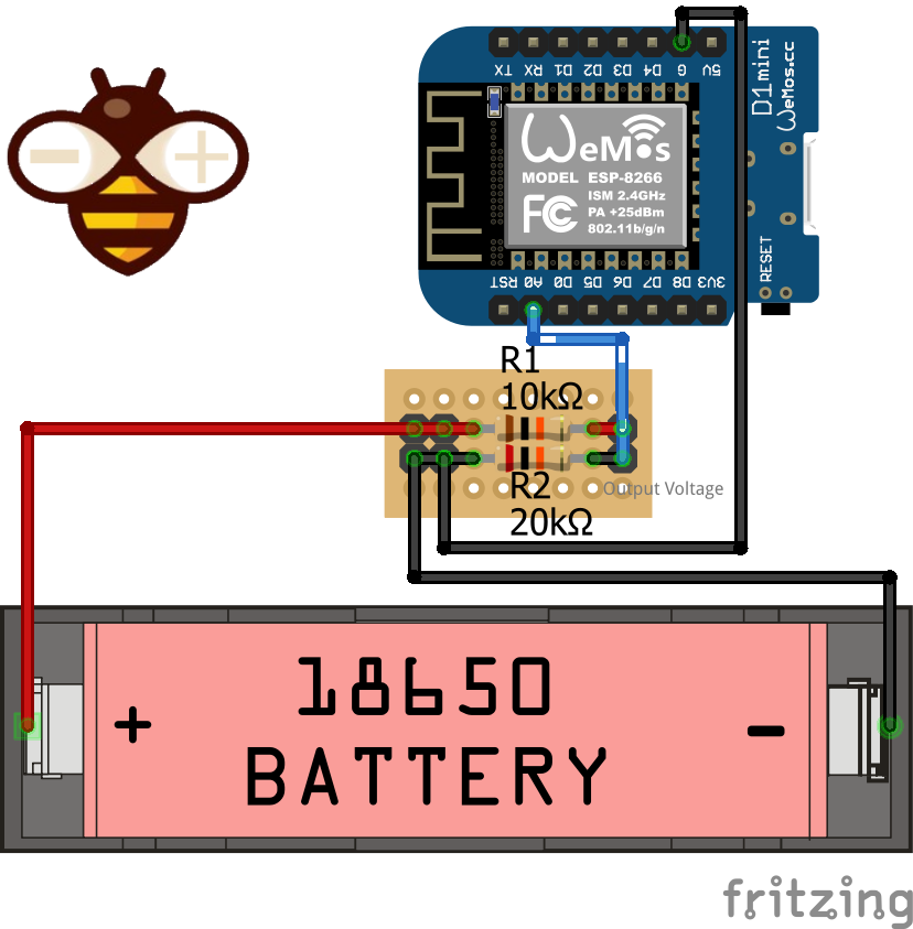
Battery can have 4.2v on full charge and when arrive to 3.3v It can be considered discharged, if you use It with esp8266 you can’t connect directly because esp analog pin have 3.3v as max input supported, and you can’t apply 4.2v.
So you must apply a voltage divider to check voltage.
I use a R1=10kohom and R2=20kohom, so when the battery have full charge (4.2v) to analog input arrive about 2.8v (check on calculator).
Remember to share Ground to have a good sample.
Pay attention the ADC of an esp8266 is from 0v to 1v, the board like WeMos D1 mini have an internal voltage divider to manage input at 3.3v.
In my current work in progress project a centraline to check the status of solar panel Inverter (an ABB Power-One)
I need to put a battery to power the microcontroller when sun is not present, here the code that I use.
// Battery voltage resistance
#define BAT_RES_VALUE_GND 20.0
#define BAT_RES_VALUE_VCC 10.0

[...]

float getBatteryVoltage(){
	//************ Measuring Battery Voltage ***********
	float sample1 = 0;
	// Get 100 analog read to prevent unusefully read
	for (int i = 0; i < 100; i++) {
		sample1 = sample1 + analogRead(A0); //read the voltage from the divider circuit
		delay(2);
	}
	sample1 = sample1 / 100;
	// REFERENCE_VCC is reference voltage of microcontroller 3.3v for esp8266 5v Arduino
	// BAT_RES_VALUE_VCC is the kohom value of R1 resistor
	// BAT_RES_VALUE_GND is the kohom value of R2 resistor
	// 1023 is the max digital value of analog read (1024 == Reference voltage)
	float batVolt = (sample1 * REFERENCE_VCC  * (BAT_RES_VALUE_VCC + BAT_RES_VALUE_GND) / BAT_RES_VALUE_GND) / 1023;
	return batVolt;
}
So I can check the status of the battery.
Pay attention 1023 is the correct value for an esp8266 but not for an esp32, for this device you must substitute this value with 4095.
Application: bluetooth RX pin
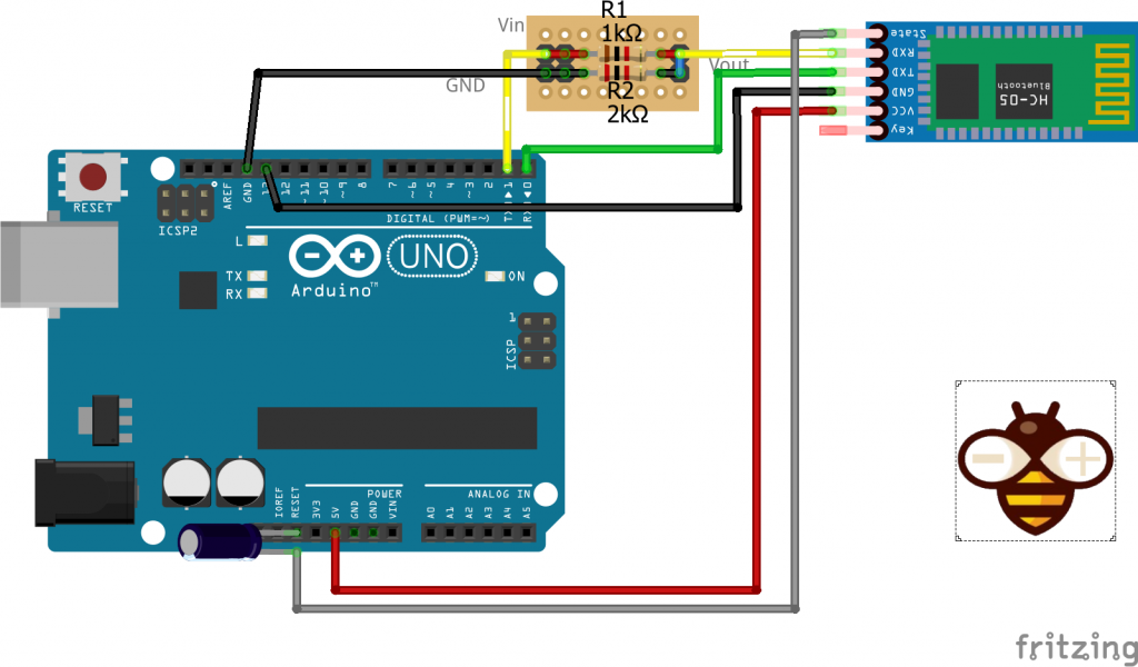
Another common application is to add a divider to RX pin of bluetooth HC-05, HC-06 or SPP-C that works at 3.3v even if have a voltage regulator to VCC in.
Thanks
I write this articles because I never remember how to calculate the resistor.


replace 1023 to 4095 since ESP32 ADC are 12bit
Thanks Moe,
i add this notation for esp32 to the article.
Bye Renzo
I have esp32 led1 pin gpio33 connected to 1uF cap and minus to ground of gournd on esp32 or i should ground it do battery ground? its go throught power bank module what is better? when i connect cap ground to battery i have lot of noise when to esp32 ground i stable but on our picture says i should connect to ground of battery?
Hi John,
the ground must be shared from battery and esp32, so there isn’t difference on GND connection.
Bye Renzo