Checking Battery Capacity with Arduino: Temperature Monitoring and Type Selection
Unraveling the veracity of a battery’s capacity is akin to unveiling the heart that powers our modern-day gadgets. Amidst an era where the marketplace is flooded with batteries claiming towering capacities, having a reliable battery capacity tester at hand is nothing short of wielding a wand of truth.
I restored this old article, which was never published, because I think it can interest many people.
Particularly for the fervent aficionados of 18650 batteries, acid batteries, and other varied types, having a precise measure of the capacity is paramount. The largest battery I’ve tested with this device is a 6V acid battery boasting a capacity of 4.2A. The results of the testing are meticulously rendered in milliampere-hours, providing a clear value into the battery’s actual prowess.
The inception of this device was fueled by a necessity— a pressing need to discern the authenticity of battery capacities, particularly those heralding from China which often sport dubious specifications.
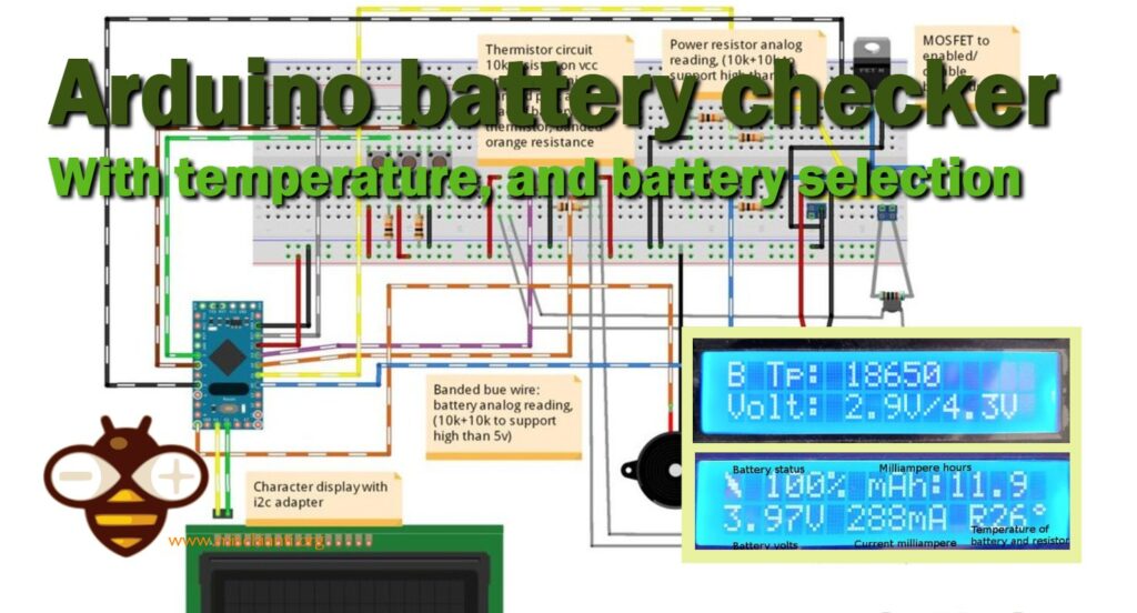
Safety is an important factor, so I pushed myself to incorporate a thermistor to monitor the temperature of the power resistance and the battery under test. This addition forestalls any overheating issues, ensuring a safe testing environment even for the 6V acid batteries.
The design intricately pauses the discharge cycle whenever the power resistor’s temperature ventures into the higher value, waiting a prudent span of 20 seconds to let the temperatures subside before resuming the test.
The heart of this tester is a compact microcontroller, specifically an Atmega328 compatible Nano sourced from AliExpress, orchestrating the operations seamlessly.
Get the Arduino Pro Mini from here Arduino UNO - Arduino MEGA 2560 R3 - Arduino Nano - Arduino Pro Mini
The complete code powering this device is shared here.
Progressive Enhancements: Evolution of the Board
Over time, refinements have been made to the board, each iteration introducing a suite of features, inching it closer to a more generalized and user-friendly avatar. Below is a chronicle of the board’s evolution, marked by two significant versions: v0.1 and v0.2.
v0.1: Laying the Foundation
- Automated Calculation: The VCC of the Arduino is now autonomously computed, eliminating manual calculations.
- Enhanced Settings Management: Introduced a variable to tweak settings effortlessly.
- Discharge Monitoring: Implemented a feature to display the percentage of discharge, offering a real-time insight into the battery’s status.
- Thermal Monitoring: Incorporated temperature monitoring for both the battery and power resistor, ensuring safe operation.
v0.2: Advancing Towards a Modular Design
- Battery Selection Feature: A new addition that facilitates the selection of different battery types.
- Prototype Board Creation: Realized a prototype board (schematic available), relocating the screen, button, and speaker off the board. This modular approach lays the groundwork for a future packaged solution.
- Temperature Limit Management: Introduced a mechanism to halt the process if the power resistor’s temperature ascends beyond 70°C, preventing derating and ensuring operational safety.
With each iteration, the board is crafted not just to test battery capacities accurately, but to offer a user-friendly, safe, and adaptive environment for all testing requisites. The journey from v0.1 to v0.2 mirrors a quest for a seamless user experience while adhering to the high standards of safety and functionality.
V0.2 Board
Tailoring the Board to Accommodate Diverse Batteries
The evolution from v0.1 to v0.2 marked a significant leap towards accommodating a diverse spectrum of batteries. This was orchestrated by crafting a structure that encapsulates the battery name alongside its minimum and maximum voltage thresholds. Below is a snippet illuminating this enhancement:
// Structure of battery type
struct BatteryType {
	char name[10];
	float maxVolt;
	float minVolt;
};
#define BATTERY_TYPE_NUMBER 4
BatteryType batteryTypes[BATTERY_TYPE_NUMBER] = {
		{ "18650", 4.3, 2.9 },
		{ "17550", 4.3, 2.9 },
		{ "14500", 4.3, 2.75 },
		{ "6v Acid", 6.50, 5.91  }
};
To accurately gauge the temperature, a voltage divider composed of a set of 10k resistors has been employed, doubling the temperature readout on the analog input. Adjusting the voltage support entails tweaking these values as illustrated below:
// Battery voltage resistance
#define BAT_RES_VALUE_GND 10.0
#define BAT_RES_VALUE_VCC 10.0
// Power resistor voltage resistance
#define RES_RES_VALUE_GND 10.0
#define RES_RES_VALUE_VCC 10.0
The implementation embraces flexibility, allowing for the disengagement of the thermistor if not in use, as depicted below:
#define USING_BATTERY_TERMISTOR true
#define USING_RESISTO_TERMISTOR true
For those employing a disparate i2c display, a method rewriting is necessitated to ensure compatibility:
void draw(void)
The project repository is a treasure trove of resources, harboring Fritzing schematics, photographs, and a plethora of additional information, aiding in both understanding and potentially extending the functionality of this versatile battery capacity tester.
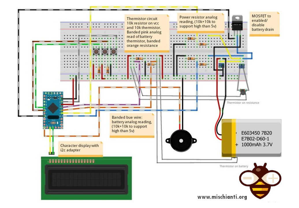
Breadboard: I2c Character Display Controller Expanded
I used a generic character display, and I built the i2c controller and used it with my custom library.
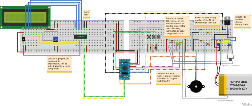
But if you want, you can take a normal i2c controller (less than 1€) with a standard library, and the code remains the same. All code of display is in draw function so you can change that without changing other things.
You can find more information here:
Breadboard: Character Display With I2c Integrated
The same schema without i2c controlled expanded.
Realization
For measuring voltage we use the principle of a Voltage divider.
Fine-Tuning Voltage and Current Measurements: Delving into the Code
The essence of accurately gauging a battery’s capacity lies in meticulous voltage and current measurements. This segment delineates the code snippets and the rationale behind the computations involved in measuring the battery voltage and deducing the current, ensuring a precise assessment of the battery’s capacity.
- Voltage Measurement Multiplier: The formula
batResValueGnd / (batResValueVolt + batResValueGnd)serves as a multiplier factor crucial for voltage measurement. Here,batResValueGndandbatResValueVoltare the values of resistances incorporated before and after the analog read wire respectively.
float multiplier = batResValueGnd / (batResValueVolt + batResValueGnd);
- Voltage Measurement: The voltage across the battery is calculated with the formula provided below, where
sample1represents the average analog readings,vccis the reference Arduino voltage, and1023.0denotes the maximum value an Arduino analog read can yield.
float batVolt = (sample1 / (1023.0 - ((BAT_RES_VALUE_GND / (BAT_RES_VALUE_VCC + BAT_RES_VALUE_GND)) * 1023.0))) * vcc;
- Current Measurement: To ascertain the current, voltage readings before and after the power resistor are imperative. Once these voltages are measured, the current (in milliampere) that the battery consumes can be calculated using Ohm’s Law.
- MOSFET Utilization: A MOSFET is deployed to initiate or halt the battery drain from the power resistor, thereby controlling the discharge process and aiding in accurate capacity measurement.
- Thermal Monitoring: For an added layer of safety, two thermistors are embedded to vigilantly monitor the temperatures of both the battery and the power resistor. This precaution ensures that the testing environment remains within safe thermal boundaries, averting any potential hazards.
The code snippets elucidated above encapsulate the essence of how voltage and current measurements are intricately linked to the accurate assessment of battery capacity, while also emphasizing on safety through thermal monitoring.
Embracing Extensibility
At the heart of this prototype board lies the essence of extensibility, although it currently harnesses only a minimal set of pins. The horizon envisions the integration of LEDs and additional buttons to augment its functionality.
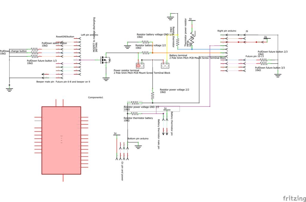
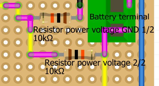
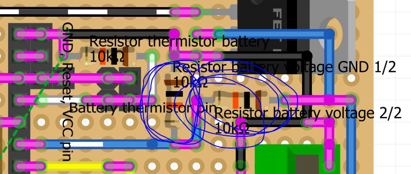
This formula is pivotal when tweaking the schema for the Resistor power voltage, delineated as:
(BAT_RES_VALUE_GND / (BAT_RES_VALUE_VCC + BAT_RES_VALUE_GND)
in the schema Resistor power voltage
Resistor power voltage GND 1/2 / (Resistor power voltage 2/2 + Resistor power voltage GND 1/2)
This articulation in the resistor values ensures that the board can accurately measure and handle the higher voltages, thereby extending its domain of applicability. The journey towards extensibility is marked by these calculated modifications, setting a trajectory towards a more versatile and adaptable board.
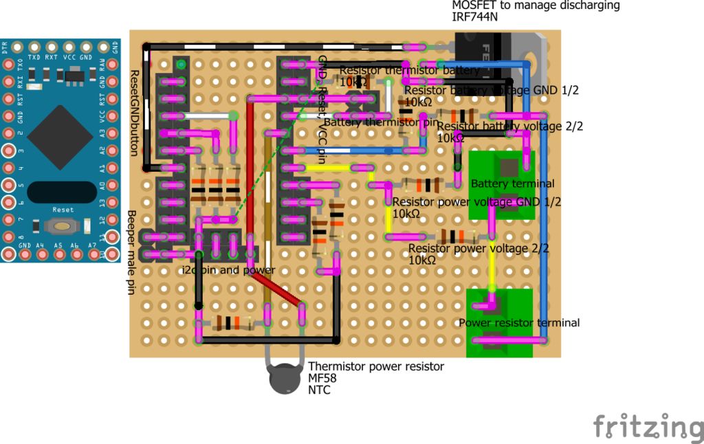
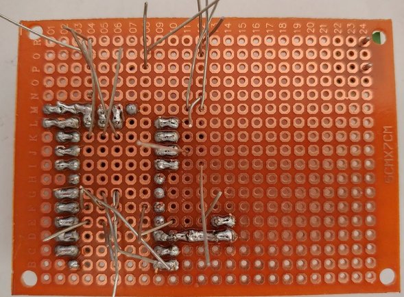
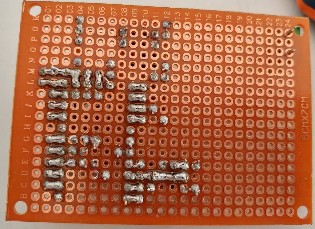
Pink is down-soldering
Bill of Materials
Quantity | Component Description | Specifications
- 2x Screw Terminal Block | 5mm Pitch, PCB Mount, 8A 250V, LW SZUS
Screw Terminal Terminal sh1.0 jst1.25 zh1.5 ph2.0 xh2.54 - 2.54mm PCB Screw Terminal Blocks
- 1x Microcontroller | Arduino Pro Mini Clone (Nano Compatible)
Pro Mini Arduino UNO - Arduino MEGA 2560 R3 - Arduino Nano - Arduino Pro Mini
- 1x MOSFET P-Channel | IRF744N or IRLZ44N
Mosfet IRFZ44 - IRLZ34N IRLZ44N - IRF744N
- 11x Resistors | 10kΩ, Standard Tolerance
- 2x Thermistors | Temperature Sensor, 10kΩ
Thermistor NTC MF58 3950 B 5% 1% 5K 10K 20K 50K 100K
- Connectors | Generic Male Headers (♂)
- Connectors | Generic Female Headers (♀)
- 1x Prototyping Board | PerfBoard, 24×18 cm
Perfored board PCB 5x7 Perfored
- 1x Power Resistor | 10Ω, 10W, salvaged from an old CRT TV
Power resistor Power resistor
Additional Components:
- Control Interface | Buttons for:
- Selecting Battery Type
- Initiating Battery Discharge
- Reset Button to Restart the System and Activate New Operations
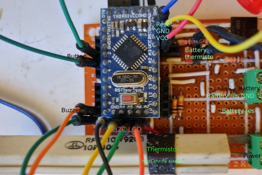
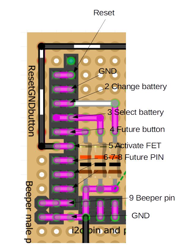
- Indicators and Interfaces | Board includes Reset, Ground, and Select Button, with Buzzer located on the left side of the pins.
All pin is already pulled down so you must activate with VCC.
Reset is activate with GND.
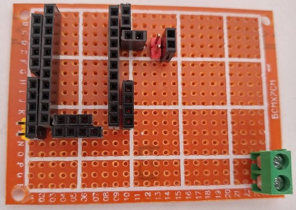
Board details
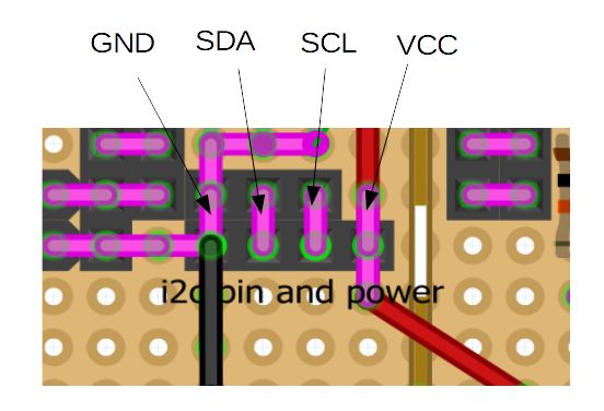
I2c and Power Supply Pins
To the base, you can see the VCC, GND and SDA, SCL for display (and other in the future).
Thermistor and Measuring Voltage
To the right, there are pins to read thermistor value, one for the power resistor thermistor and the other for (male/female pins to attach) battery thermistor.
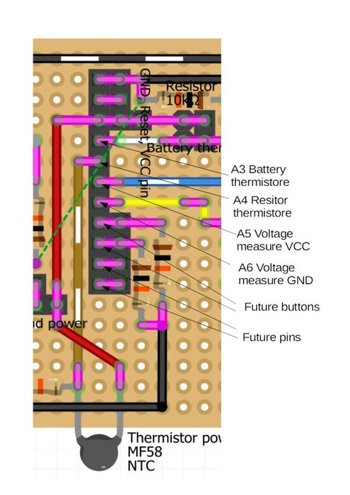
Then there are analog pins that measure differential voltage after and before the power resistor.
Resistor to Measuring Voltage
Here you can see the resistor that permits to support voltage double than Arduino pin (10v). You must change this to support more voltage.
Soldering Step
It’s time to solder and assemble.
All Pins
First, I added all the pins and soldered Them.
Pulldown Resistors and Thermistors
Then I add all pulldown resistors (for buttons) and i2c connectors (display).
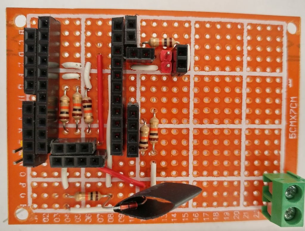
Then the power resistor thermistor It’s very important, with the acid battery going too hot.
MOSFET, Resistance to Check Voltage
Now, we must insert mosfet to activate discharging and resistance to check voltage.
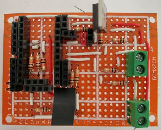
2 resistance for voltage before power resistor 2 resistance for voltage after power resistor. When you have this voltage you can calculate milliampere consumption.
Instructions for Setting Up the Microcontroller:
- Configure Your IDE: The microcontroller used is a Nano-compatible Arduino Pro Mini clone. To upload sketches, set your IDE to recognize the board as an Arduino Nano.
- Code Acquisition: The necessary code can be obtained from my GitHub repository. Ensure you download the latest version for proper functionality.
- Library Integration: You will need to incorporate three specific libraries for the project:a. Wire Library: This is a standard library available in the Arduino IDE, used for I2C communication.b. Thermistor Library: Do not use the default version found in the Arduino IDE. Instead, use my customized version, which can be downloaded from the provided link.c. LiquidCrystal_i2c Library: For those using a non-standard or custom I2C adapter, my version of this library should be used. It is available via a separate link. If your component is standard, the Arduino IDE’s built-in library will suffice. Detailed instructions and differences are explained further at the specified link.
- LCD Compatibility Note: The operation of the LCD with the standard library has not been tested. It’s recommended to follow the instructions carefully for successful integration of the custom libraries provided.
Start usage
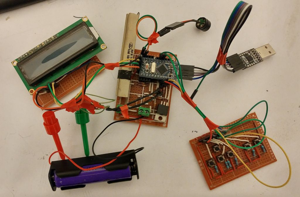
The baseboard is in the photo, and then we can go to test It. Here a demonstrating video.
Here are the connections.
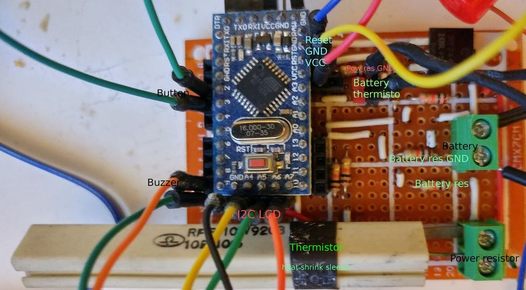
Finally assembled and working.
First Select Battery Type
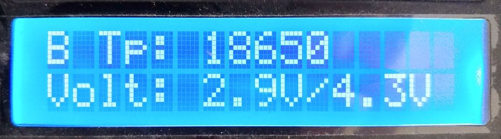
As described we have a map of value with the configuration of the battery.
// Structure of battery type<br>struct BatteryType {
	char name[10];
	float maxVolt;
	float minVolt;
};
#define BATTERY_TYPE_NUMBER 4
BatteryType batteryTypes[BATTERY_TYPE_NUMBER] = {
		{ "18650", 4.3, 2.9 },
		{ "17550", 4.3, 2.9 },
		{ "14500", 4.3, 2.75 },
		{ "6v Acid", 6.50, 5.91  }
};
Start Discharging
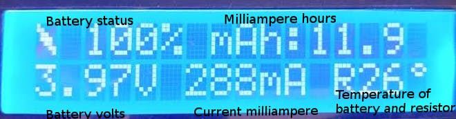
Click the second button to start discharging.
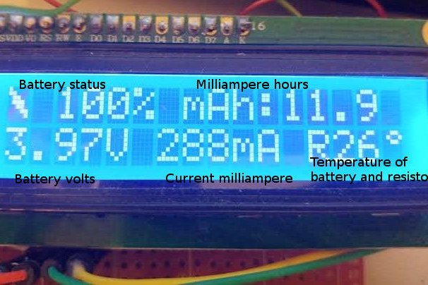
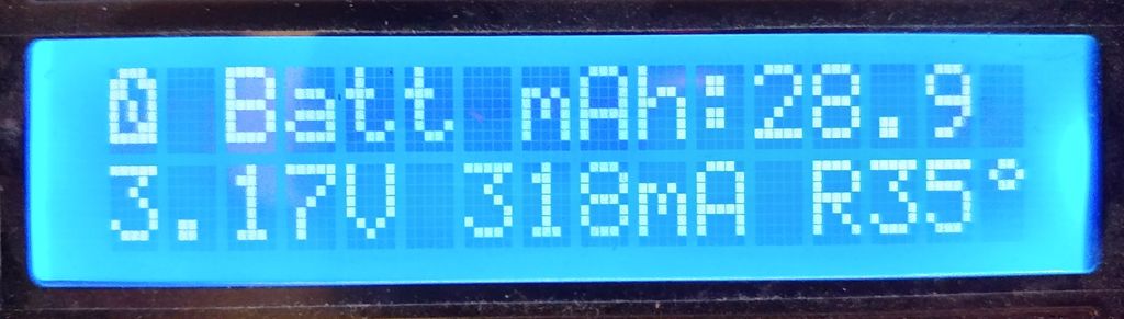
The display shows the current milliampere, milliampere/hours, percentage of discharging, battery voltage, and temperature of the power resistor and battery.
Exceptions: Battery Removed
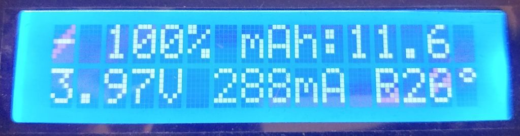
If you remove the battery, the discharging process will pause when you reinsert. It restarts at the last value.
Here is the result on screen.
Exceptions: Temperature Alert
If the temperature (battery or power resistor) is going to be hot, the discharging process goes to pause.
#define BATTERY_MAX_TEMP 50
#define RESISTANCE_MAX_TEMP 69 // 70° on datasheet (Derating resistors)
#define TEMP_TO_REMOVE_ON_MAX_TEMP 20
The default value for max temperature is 50° for the battery and 69 for the power resistor.
As you can see in the comment, the power resistor is affected by derating when going over 70°.
If alert is raised, start TEMP_TO_REMOVE_ON_MAX_TEMP seconds of pause to put low temp.
Test Amperage
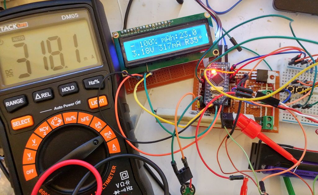
The result of the amperage test is good.
Streamlined Packaging with Separate Components
The strategy of utilizing separate components significantly simplifies the packaging process, leading to a more straightforward realization of the finished product.
The envisioned enclosure is designed to encompass an array of features:
- A designated rectangle for the LCD display ensures clear visibility and easy access.
- Strategically placed holes for the push buttons, facilitating effortless user interaction.
- An external female barrel connector enables hassle-free voltage supply from an external power source.
The integration of a pull-down resistor on the board eliminates the need for one alongside the push button. This thoughtful addition streamlines the setup and augments the ease of assembly.
The manifestation of this setup is on the horizon. When time permits, the complete assembly will be crafted and shared, embodying a seamless blend of functionality and user-friendly design.
Thanks
To simplify the process, I will create a simple PCB. Stay tuned.