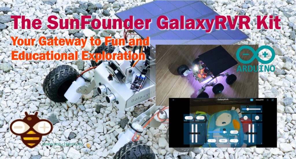
Space Education: The Enhanced GalaxyRVR Mars Rover Kit with Light and Signal Booster
The SunFounder GalaxyRVR Mars Rover Kit is an innovative and educational tool for exploring robotics and space technology. This Arduino-based kit is modeled after NASA’s Mars rovers, featuring a rocker-bogie suspension system allowing smooth movement over different terrains. Key technical specifications include a camera providing a first-person view, sensors for obstacle detection and avoidance, and programmable capabilities for custom functionalities. This kit serves as a practical and engaging way to learn about robotics, programming, and space exploration technologies.
Designed to ignite curiosity and foster learning, this kit blends the thrill of space exploration with hands-on experience in robotics. By replicating the mechanics of real Martian rovers, it offers enthusiasts, students, and educators alike a unique opportunity to delve into the world of space technology and robotics, bridging the gap between theoretical learning and practical application.
You can buy It here.
Design
This sophisticated design is not only integral to the rover’s mobility but also provides an insightful glimpse into the engineering challenges and solutions of real-world space exploration vehicles.
Technical specifications
The technical prowess of the SunFounder GalaxyRVR Mars Rover Kit is highlighted by its camera, sensors for obstacle detection, and Arduino-based programming. The camera offers a first-person view, simulating the perspective of exploring a Martian landscape. Its sensors are adept at detecting and navigating around obstacles, crucial for replicating the challenges faced by real rovers on uneven terrains. The Arduino-based programming element adds an educational dimension, allowing users to delve into coding and robotics, enhancing both their technical skills and understanding of space technology. These features collectively make the GalaxyRVR not just a tool for exploration but also a comprehensive educational resource.
- SunFounder R3 Board: A microcontroller board based on the ATmega328P, similar in function to the Arduino Uno. It has 14 digital input/output pins, 6 analog inputs, a 16 MHz ceramic resonator, USB connection, power jack, ICSP header, and reset button. It’s the heart of the rover, driving its various functions.
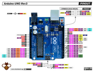
Arduino UNO Arduino UNO - Arduino MEGA 2560 R3 - Arduino Nano - Arduino Pro Mini
- GalaxyRVR Shield: This shield is designed for easy connection of various components to the SunFounder R3 Board. It includes a charge port, battery port, reset button, and several charges, power, and battery indicators. It also features multiple ports for motors, RGB LED strips, obstacle avoidance, camera adapter, and ultrasonic sensors, along with a mode switch for the ESP32-CAM and solar panel port.
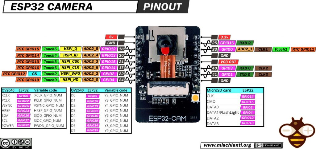
- ESP32 CAM: This is a camera module with Bluetooth and Wi-Fi capabilities. It supports various interfaces like UART, SPI, I2C, and PWM and can handle image output in formats like JPEG, BMP, and Grayscale. The module is designed to be energy-efficient and operate in a wide range of temperatures.
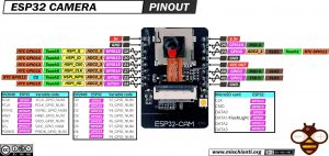
ESP32-CAM and programmer AliExpress ESP32-CAM programmer - AliExpress ESP32-CAM bundle
- Camera Adapter Board: This board is designed to connect the ESP32-CAM to the rover. It includes several pins for resetting the ESP32-CAM, serial data, and clock pins for the QMC6310, RXD and TXD for uploading code, and a 5V DC supply input.
- Ultrasonic Module: The HC-SR04 ultrasonic distance sensor is used for non-contact measurement ranging from 2 cm to 400 cm. It includes an ultrasonic transmitter, receiver, and control circuit. The module operates on a 5V supply and can be easily connected via its four pins.
- IR Obstacle Avoidance Module: Essential for the rover’s navigational capabilities, allowing it to detect and avoid obstacles.
- RGB LED Strip: These strips are used for visual effects and indicators, adding an aesthetic dimension to the rover.
- TT Motor: Powers the movement of the rover, crucial for its mobility.
- Solar Panel: Provides a renewable energy source, allowing the rover to be powered sustainably.
- 18650 Battery: Acts as the primary power source for the rover.
Assembly process
The assembly process and programming environment of the SunFounder GalaxyRVR Mars Rover Kit offer a blend of challenge and learning opportunities, suitable for enthusiasts at various skill levels.
Assembly Process:
- The assembly of the GalaxyRVR is a hands-on experience. It requires careful attention to detail, as it involves several small parts and intricate steps.
- The process is designed to be educational, with each step offering insight into the mechanics of rover construction. It’s akin to building a model, but with more complex, functional components.
- The level of difficulty is moderate. It’s challenging enough to be engaging for those with some experience in building kits or models, but not overly complex for beginners.
- Instructions are usually clear, but some steps might require a bit of problem-solving to enhance the learning experience.
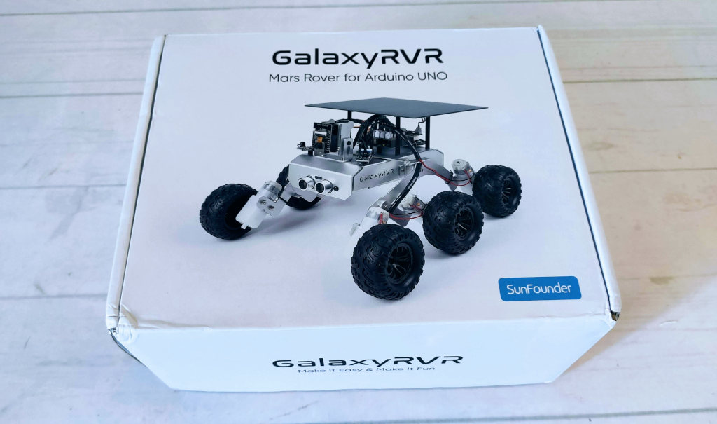
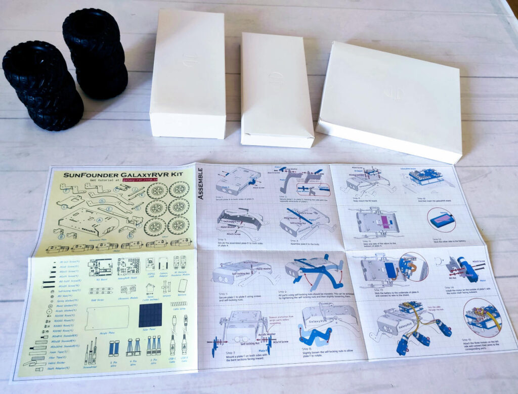
Unboxing the GalaxyRVR: The package reveals three sub-packets containing wheels and opened instructions. Excitement builds as the rover assembly begins.
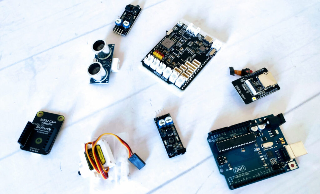
Inside the first sub-packet, a treasure trove of components awaits. The package reveals the Arduino UNO, the GalaxyRVR shield, the ESP32-CAM, the ESP32-CAM holder, two IR sensors, the Ultrasonic sensor, and a servo motor for managing the camera’s vertical position. These crucial elements will form the backbone of the GalaxyRVR’s functionality.
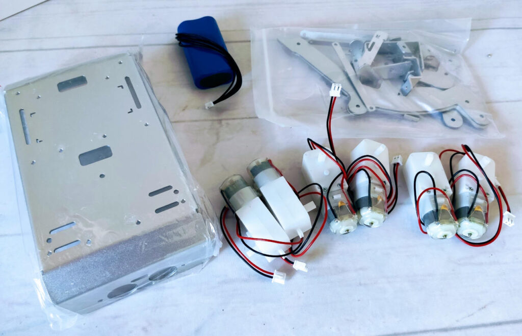
In the second sub-packet, the essential power source and mechanical components are unveiled. This package contains the lithium battery pack, which will fuel the GalaxyRVR’s adventures, as well as six motors that will drive its movements. Additionally, it includes aluminum elements for the basic structural framework, setting the stage for the rover’s robust construction.
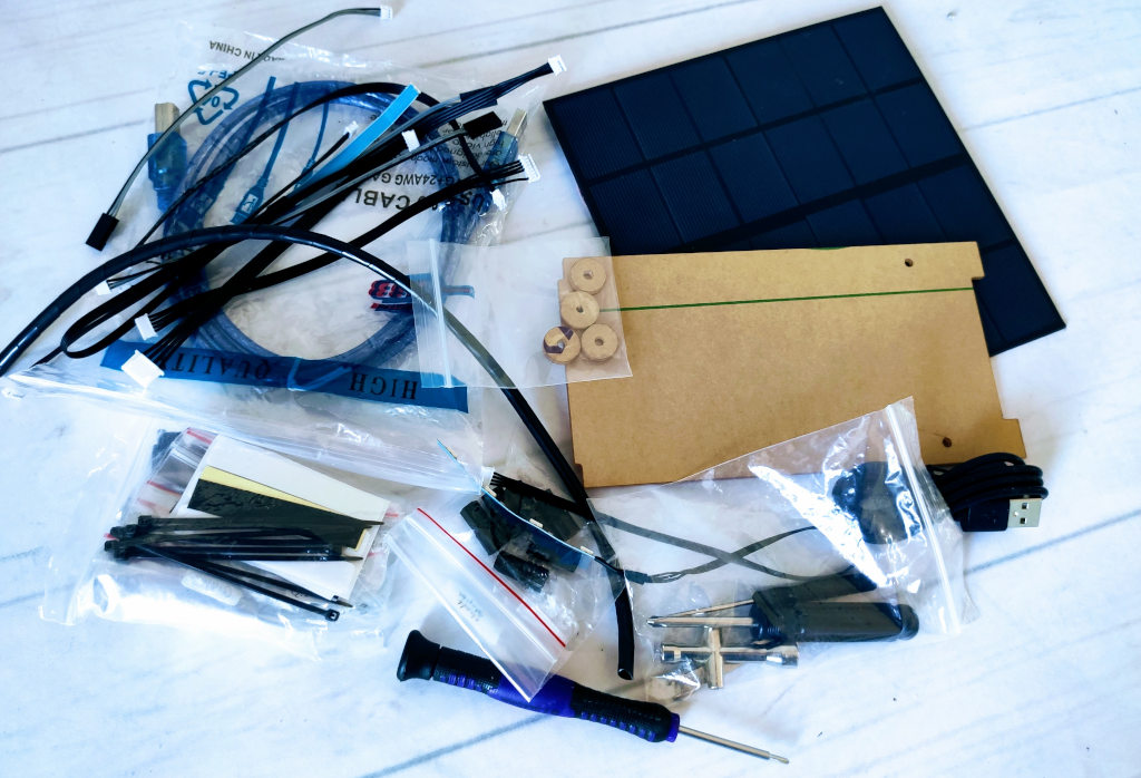
The third sub-packet completes the GalaxyRVR assembly puzzle with a variety of remaining components. It includes an assortment of cables for connecting the various parts, ensuring seamless communication within the rover. Additionally, it houses the solar panel, an integral component for sustainable power. Acrilic parts are also found within, contributing to the rover’s overall structure and design. Furthermore, essential tools like screwdrivers are included, facilitating the assembly process and making sure no detail is overlooked. This comprehensive collection of components ensures that every aspect of the GalaxyRVR comes together seamlessly.
The first assembly step captures the beginning of the GalaxyRVR’s construction journey. It showcases the initial stages of assembling the basic structure, extending it to its maximum dimensions. This step is foundational, setting the stage for the rover’s complete assembly and eventual exploration of its surroundings.
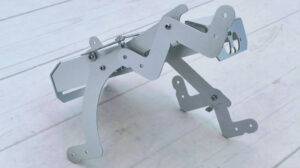
Another perspective.
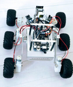
In this assembly step, the GalaxyRVR takes a significant leap forward in its construction process. The motors, Arduino UNO, and GalaxyRVR shield are skillfully attached, forming the core of the rover’s mechanical and electronic systems. Every cable is meticulously connected, ensuring seamless communication between components. This step marks a crucial milestone in bringing the GalaxyRVR to life, setting the stage for its dynamic functionality.
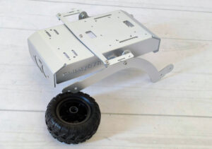
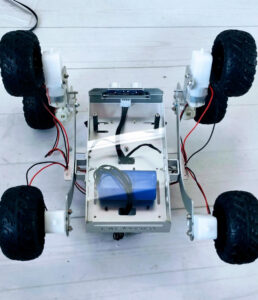
This image provides a clear view of the rover’s underside, highlighting the precise location where the battery pack has been securely attached. This essential step ensures that the GalaxyRVR has a reliable power source for its missions and expeditions.
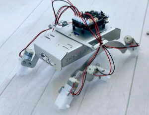
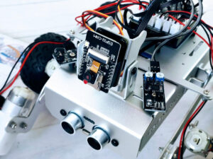
This photograph showcases a pivotal moment in the GalaxyRVR assembly process. The IR and ultrasonic sensors have been expertly attached and wired, enhancing the rover’s navigational capabilities. Additionally, the wheels have been skillfully assembled, setting the stage for the rover’s mobility and exploration.
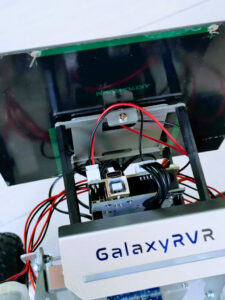
In this detailed view, the fully assembled ESP32-CAM module can be seen, securely mounted on its mobile support. This setup allows the rover to capture images and video with precision, enhancing its observational capabilities for remote exploration.
This perspective offers a view of the rover’s bottom, where the acrylic protection serves as a safeguard for its delicate components. This protective layer shields the rover’s vital electronics, ensuring their safety during missions and adding an extra layer of resilience to the GalaxyRVR.
This overhead view highlights the solar panel support structure, a key component of the GalaxyRVR. The support ensures the solar panel is optimally positioned to harness sunlight, providing sustainable power for the rover’s operations and enabling extended exploration.
In this detailed rear view, the fully assembled solar panel can be seen. It is securely attached to the rover’s structure, ready to capture solar energy from the environment. This component plays a crucial role in powering the GalaxyRVR during its missions, making it more versatile and sustainable.
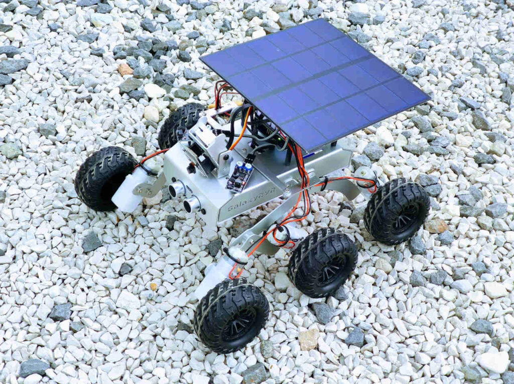
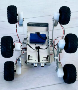
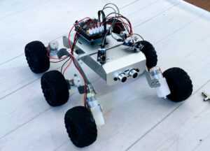
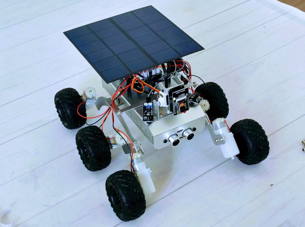
This captivating image showcases the SunFounder GalaxyRVR Mars Rover Kit in all its glory, fully assembled and ready for action. Every component has been skillfully integrated, from its mechanical structure to its electronic systems. The GalaxyRVR embodies the spirit of exploration and innovation, poised to embark on exciting journeys and educational adventures.
Play Mode
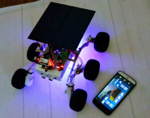
Are you eager to kick-start your Martian journey right away? Our Play Mode is perfectly tailored for those of you who just can’t wait to dive in. Equipped with factory-preloaded code, you can jump straight into the action after assembling your GalaxyRVR. Use the user-friendly SunFounder Controller app to explore its myriad of functions including first-person driving, switching between obstacle avoidance and follow modes, and even voice control.
Quick Guide:
- Let’s start the GalaxyRVR.
- The first time you use your GalaxyRVR, it is recommended that you plug in a Type-C USB cable to fully charge the battery first. Then turn the power on.
- To activate the ESP32 CAM, move the mode switch to the Run position, and press the reset button to reboot the R3 board. You will then observe a cyan light flashing on the bottom strip.
- Install SunFounder Controller from APP Store(iOS) or Google Play(Android).
- Connect to the GalaxyRVR Network.
- For optimal communication between your mobile device and the Rover, you’ll need to connect them to the same local area network (LAN) provided by GalaxyRVR.
- Find GalaxyRVR on the list of available networks on your mobile device (tablet or smartphone), enter the password 12345678, and connect to it.
- The default connection mode is AP mode. After you’ve connected, there might be a prompt warning that there is no internet access on this network. If so, choose “Stay connected”.
- Set up a controller.
- To create a controller on SunFounder Controller, tap the + icon.
- Preset controllers are available for some products, here we choose GalaxyRVR. Give it a name, or simply tap Confirm.
- Once inside, the app will automatically search for the GalaxyRVR. After a moment, you will see a prompt saying “Connected Successfully”.
- If not connected, please confirm that your Wi-Fi is connected to GalaxyRVR.
- You can also tap the app_connect button to connect manually. After a short wait, you should see GalaxyRVR(IP) appear. Tap on it to establish a connection.
- Now, tap the app_run button enables you to view the live video feed from the camera and control the car using the provided widgets.
Let’s now delve into the functions of each widget:
- Servo(D): Controls the tilt mechanism of the Rover’s camera, allowing you to observe a wider range.
- Avoid(E): Switches the Rover into obstacle avoidance mode. The factory-set detection distances for each obstacle avoidance module may differ. Manual adjustment is required.
- Follow(F): Toggles the Rover into follow mode. The factory-set detection distances for each obstacle avoidance module may differ. Manual adjustment is required.
- Stop(I): Immediately halts all Rover movements.
- STT(J): Press this widget to initiate voice recognition and make the Rover perform corresponding actions.
- HeadLamp(M): To turn the LED on/off on the ESP32 CAM.
- Throttle Widgets on K and Q: The throttle widget in the K area controls the Rover’s left motors, while the one in the Q area controls the right motors. Coordinating both widgets allows the GalaxyRVR to move in any direction.
- Left IR(N): Displays the readings from the left obstacle avoidance module.
- Ultrasonic(O): Shows the distance measured by the ultrasonic module.
- Right IR(P): Displays the readings from the right obstacle avoidance module.
Avoid(E): Tap the Avoid(E) widget to activate the obstacle avoidance mode.
Before enabling this mode, you may need to adjust the detection ranges of the sensors according to your current environment, as the factory settings may not be ideal for all situations.
If the detection range of the two infrared modules is too short, the Mars Rover might bump into obstacles. Conversely, if the range is too long, the Rover might start swerving too far away from an obstacle, potentially disrupting its navigation.
Here’s how you can fine-tune the settings:
- Start by adjusting the right obstacle avoidance module. During transportation, collisions may cause the transmitter and receiver on the infrared module to tilt. Therefore, you need to manually straighten them.
- Place an obstacle about 20 cm directly in front of the right module. The box in which our Rover kit came is a good choice for this! Now, turn the potentiometer on the module until the indicator light on the module just lights up. Then, keep moving the obstacle back and forth to check if the indicator light comes on at the desired distance. If the light doesn’t turn on at the correct distance or if it remains on without going out, you’ll need to adjust the other potentiometer.
- Repeat the same process for the other module.
Course Mode
The GalaxyRVR, a product of SunFounder, offers a documentation section known as the “Course Mode.” This is designed for those who have already explored the Play Mode and are eager to delve deeper into the mechanics of how each function operates. The primary objective of this mode is to provide users with a comprehensive understanding of the functionalities and empower them to modify effects based on their preferences and ideas.
Educational Aspect
- Structured Learning: The programming mode is structured meticulously, with each function being categorized into a separate project. In total, there are 17 distinct projects. This modular approach ensures that learners can focus on one aspect at a time, making the learning process more manageable and systematic.
- Detailed Explanations: Accompanying each project is a set of codes and their respective explanations. This ensures that learners not only know what a particular piece of code does but also understand the underlying logic and reasoning behind it. Such a detailed approach reinforces learning and promotes a deeper understanding of the subject.
- Hands-on Experience with Arduino: The projects within the programming mode utilize the Arduino programming language. This offers learners an opportunity to familiarize themselves with one of the most popular microcontroller platforms. Before diving into the projects, users are guided to install the Arduino IDE and the necessary libraries, ensuring they have all the tools needed to embark on their programming journey.
- Diverse Range of Projects: The 17 projects cover a wide array of functionalities, from basic movements and remote control to more advanced features like AI detection from an app and obstacle avoidance. This diversity ensures that learners are exposed to various aspects of robotics and programming, making their learning experience holistic and comprehensive.
- Journey of Discovery: The programming mode is not just about coding; it’s about embarking on a journey of discovery. As learners progress through the projects, they’ll encounter challenges, solve problems, and, most importantly, witness their ideas come to life. This experiential learning approach is invaluable in instilling confidence and fostering a love for robotics and programming.
The Course Mode is an educational tool. It bridges the gap between theory and practice, allowing users to apply what they’ve learned in real-world scenarios. Whether you’re a novice looking to get started in the world of robotics or an experienced programmer seeking to expand your horizons, the GalaxyRVR’s Programming Mode offers a rich, immersive, and, above all, educational experience.
Little enhancements
As for other devices, I’d like to suggest some enhancements.
Adding an antenna
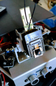
An additional improvement can be made to the GalaxyRVR’s ESP32-CAM by adding an antenna to enhance signal reception. This modification allows for a more stable and powerful signal, enabling the rover to communicate more reliably with the remote control device. The antenna can be strategically positioned to maximize signal coverage, allowing the GalaxyRVR to perform its functions more efficiently, especially in environments where connectivity may be reduced. This improvement is particularly useful when exploring larger areas or facing long-distance communication challenges.
Here the antenna I use 8dbi WiFi antenna
Add a light management
You can find this development in this article.
Here, I add a recap.
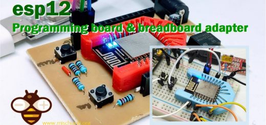
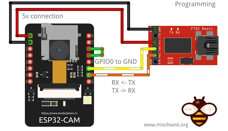
Here the ESP32-CAM and the programmer board AliExpress ESP32-CAM programmer - AliExpress ESP32-CAM bundle
From a technical standpoint, the GalaxyRVR harnesses the capabilities of the ESP32-CAM module for its video streaming functions.
For those who have followed my technical writings, I’ve extensively covered the ESP32-CAM in a series of articles. One such article specifically addresses the integration of a flashlight control mechanism, titled “ESP32-CAM: Upgrade CameraWebServer with Flash Feature”. Given this prior exploration, it becomes a logical step to leverage this knowledge for the GalaxyRVR’s lighting needs.
Our technical roadmap involves a two-pronged approach:
- Firmware Modification: We aim to modify the ai-camera-firmware, enhancing its capabilities to support the new lighting feature.
- Interface Enhancement: A new widget will be introduced to the GalaxyRVR Control dashboard. This widget is designed to activate the flashlight and provide granular control over its intensity, ensuring adaptability to diverse lighting conditions.
For a deeper dive into the technical intricacies of the ESP32-CAM and its various applications, I invite you to explore the comprehensive list of articles available here.
Communication between Arduino and ESP32-CAM
The interaction between the ESP32-CAM and the GalaxyRVR Arduino Firmware is orchestrated through two primary communication channels: Serial and WebSocket.
The Serial interface serves as the primary communication channel. Through this interface, the GalaxyRVR Arduino Firmware uses specific commands to initialize and configure the ESP32-CAM.
GalaxyRVR version 1.1.0
Initialzing...
SET+RESET
...[OK]
ESP32 firmware version 1.3.1
SET+NAMEGalaxyRVR
...[OK]
SET+TYPEGalaxyRVR
...[OK]
SET+SSIDGalaxyRVR
...[OK]
SET+PSK12345678
...[OK]
SET+MODE2
...[OK]
SET+PORT8765
...[OK]
SET+START
...[OK]
WebServer started on ws://192.168.4.1:8765
Okie!
[CAM_I] camera stream start on: http://192.168.4.1:9000/mjpg
During the initialization phase, a series of Serial commands are sent to set up the ESP32-CAM to operate in AP (Access Point) mode. The handshake begins with the GalaxyRVR announcing its version as “GalaxyRVR version 1.1.0” and initializing. Following this, a series of commands are sent:
- SET+RESET to reset settings, receiving an acknowledgment with “…[OK]”.
- The ESP32-CAM then announces its firmware version as “ESP32 firmware version 1.3.1”.
- SET+NAMEGalaxyRVR to set the device name.
- SET+TYPEGalaxyRVR to define the device type.
- SET+SSIDGalaxyRVR and SET+PSK12345678 to set up the network credentials.
- SET+MODE2 to configure the device in AP mode.
- SET+PORT8765 to specify the WebSocket server port.
- Finally, SET+START is sent to initiate the connection, and upon success, the ESP32-CAM confirms with “WebServer started on ws://192.168.4.1:8765” and “Okie!”. Additionally, the camera stream starts and is accessible at “http://192.168.4.1:9000/mjpg“.
On the other hand, the WebSocket, implemented in the ai-camera-firmware, acts as the secondary communication medium. This channel is primarily used by the SunFounder Control app to relay commands to the ESP32-CAM. Messages sent via WebSocket are structured in a positional format.
The code that manages this is in ai-camera-firmware/ws_server.cpp
[...]
    // receive text
    case WStype_TEXT:{
      ws_connected = true;

      out = intToString(payload, length);

      // reset ping_pong time
      lastPingPong = millis();
      if (strcmp(out.c_str(), "ping") == 0) {
        Serial.println("[APPSTOP]");
        return;
      }

      // ------------- send simplified text -------------
      DynamicJsonDocument recvBuffer(WS_BUFFER_SIZE);
      deserializeJson(recvBuffer, out);
      String result = "WS+";

      // REGIONS
      for (int i=0; i<REGIONS_LENGTH; i++){
        String region = String(REGIONS[i]);
        String value;
        if (recvBuffer[region].is<JsonArray>()) {
          for (int j=0; j<recvBuffer[region].size(); j++) {
            value += recvBuffer[region][j].as<String>();
            if (j != recvBuffer[region].size()-1) value += ',';
          }
        } else {
          value = recvBuffer[region].as<String>();
        }

        if (value == "true") value = "1";
        else if (value == "false") value = "0";
        if (value != "null") result += value;
        if (i != REGIONS_LENGTH - 1) result += ';';
      }

      // send
      if (millis() - last_send_time > SEND_INTERVAL ) {
        Serial.println(result);
        last_send_time = millis();
      }
      break;
    }
    // For everything else: do nothing
[...]
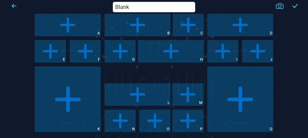
Each message arrives in JSON format, and each position in the message corresponds to a specific value. In the SunFounder Control app, every widget or control element is represented by a unique letter. Each of these letters corresponds to a specific position in the message array. For instance, the letter “L” represents the eleventh value in the message.
Upon receiving a WebSocket message, the ESP32-CAM firmware translates it into a Serial message, such as WS+;;;;;;;;;;;100;;;;;;;;;;;;;;. This format indicates that the position represented by “L” has a value of 100. The ESP32-CAM then sends this Serial message to the GalaxyRVR Arduino Firmware. Upon receipt, the Arduino firmware processes the message and triggers the corresponding function or action. In essence, the SunFounder Control app communicates user commands via WebSocket to the ESP32-CAM, which then translates these commands into Serial messages. These messages are subsequently processed by the GalaxyRVR Arduino Firmware to execute specific functions or actions.
Mod the ai-camera-firmware to manage light
Now, first, you must download the ai-camera-firmware from Git Hub. You can use the git client or download directly from here.
Now open the ino file from your preferred IDE (Arduino IDE works well and to configure ESP32 boards, refer to “ESP32-CAM: pinout, specs and Arduino IDE configuration“).
Dependencies
- WebSockets by Markus Sattler
- ArduinoJson
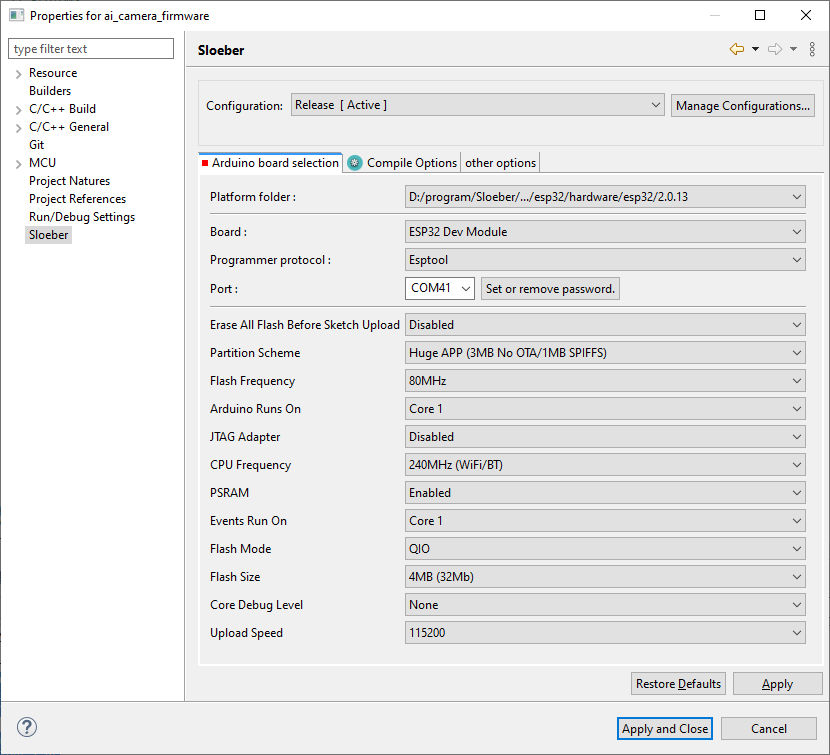
Flash settings
Board: "ESP32 Dev Module"
Upload Speed: "115200" ## You can try more but some device don't work
CPU Frequency: "240MHz (WiFi/BT)"
Flash Frequency: "80MHz"
Flash Mode: "QIO"
Flash Size: "4MB (32Mb)"
Partition Scheme: "Huge APP (3MB No OTA/1MB SPIFFS)"
Core Debug Level: "None"
PSRAM: "Enabled"
Arduino Runs On: "Core 1"
Events Run On: "Core 1"
Now proceed to the change of ws_server.cpp file. First, add 2 define to centralize the configuration:
#include "pins.h"

#define BRIGHTNESS_MULTIPLIER 0.5
#define CAMERA_PIN_FLASH 4
Then, modify the code to parse the eleventh value and set it to LED.
    // receive text
    case WStype_TEXT:{
      ws_connected = true;

      out = intToString(payload, length);

      // reset ping_pong time
      lastPingPong = millis();
      if (strcmp(out.c_str(), "ping") == 0) {
        Serial.println("[APPSTOP]");
        return;
      }

      // ------------- send simplified text -------------
      DynamicJsonDocument recvBuffer(WS_BUFFER_SIZE);
      deserializeJson(recvBuffer, out);
      String result = "WS+";

      // REGIONS
      for (int i=0; i<REGIONS_LENGTH; i++){
        String region = String(REGIONS[i]);
        String value;
        if (recvBuffer[region].is<JsonArray>()) {
          for (int j=0; j<recvBuffer[region].size(); j++) {
            value += recvBuffer[region][j].as<String>();
            if (j != recvBuffer[region].size()-1) value += ',';
          }
        } else {
          value = recvBuffer[region].as<String>();
        }

        if (value == "true") value = "1";
        else if (value == "false") value = "0";
        if (value != "null") result += value;
        if (i != REGIONS_LENGTH - 1) result += ';';

        if (i==11 && value != "null" && value != "" && ledPrecValue != value.toInt()) {
//        	Serial.print(i);Serial.print(" - ");
//			Serial.println(value);

        	ledPrecValue = value.toInt();
        	analogWrite(CAMERA_PIN_FLASH, (int)ledPrecValue*BRIGHTNESS_MULTIPLIER);
		}

      }

      // send
      if (millis() - last_send_time > SEND_INTERVAL ) {
        Serial.println(result);
        last_send_time = millis();
      }
      break;
    }
    // For everything else: do nothing
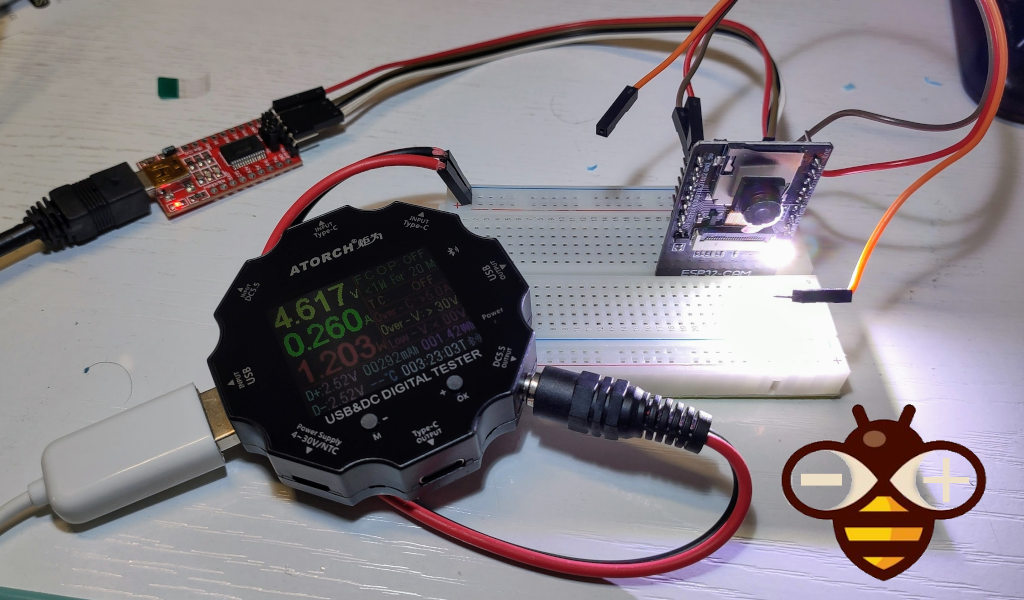
The code is very simple. I check the eleventh element value and get It, and I apply a multiplier that is lower than one because, with max power, the flash sometimes gets too much power and freezes the device (so you can preserve the power), and I set with PWM the value to the camera flash pin (in my case the pin 4 like described in the article linked before).
        if (i==11 && value != "null" && value != "" && ledPrecValue != value.toInt()) {
//        	Serial.print(i);Serial.print(" - ");
//			Serial.println(value);

        	ledPrecValue = value.toInt();
        	analogWrite(CAMERA_PIN_FLASH, (int)ledPrecValue*BRIGHTNESS_MULTIPLIER);
		}

      }
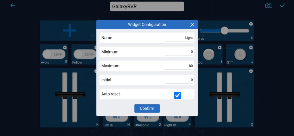
Now, we must set the correct widget at the correct position; position L is the eleventh element, and you must put the control widget there.
To do that, open the SunFounder controller and add GalaxyRVR control. After that, click on the edit button in the top right corner.
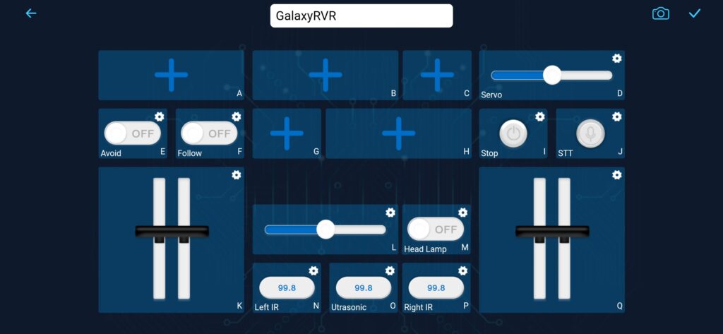
I change only the name and the initial value.
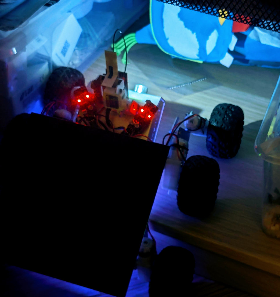
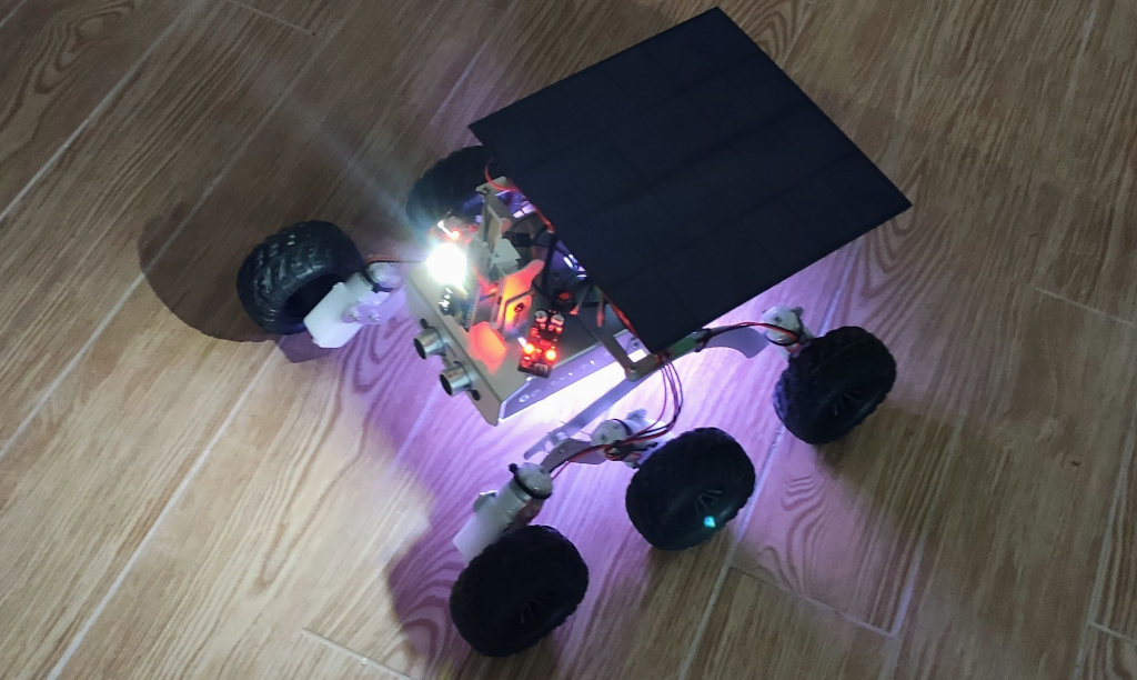
And now, in action, inside the wardrobe, go to discover where the backpack is.
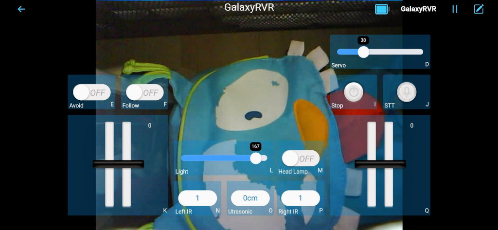
Here the Rover in action.