
Ciclop 3D scanner: assembling electronic and wiring – 3
After assembling the basic mechanical components it is now time to assemble and connect all the electronic parts.
The original documentation is lost, so I grab the old material from the net and I translate and rewrite in this article.
List of standard material to assembly
2 x Laser
1 x C270 Logitech® HD Webcam
1 x bq ZUM BT-328 controller board
1 x bq ZUM SCAN Power Shield
1 x Stepstick Drivers A4988 4 layers
2 x Laser cable duct printed part: 80 mm
1 x Printed part motor cable duct: 240 mm
1 x Printed part electronic cap
1 x Micro-USB Cable
1 x Power supply 12 V 1.5 A
1 x Methacrylate front pattern
1 x Printed part pattern holder
1 x Checkerboard pattern sticker
2 x Screw M3 x 10 mm – DIN 912 class 8.8 black
2 x Nut M3 – DIN 934 class 8 black
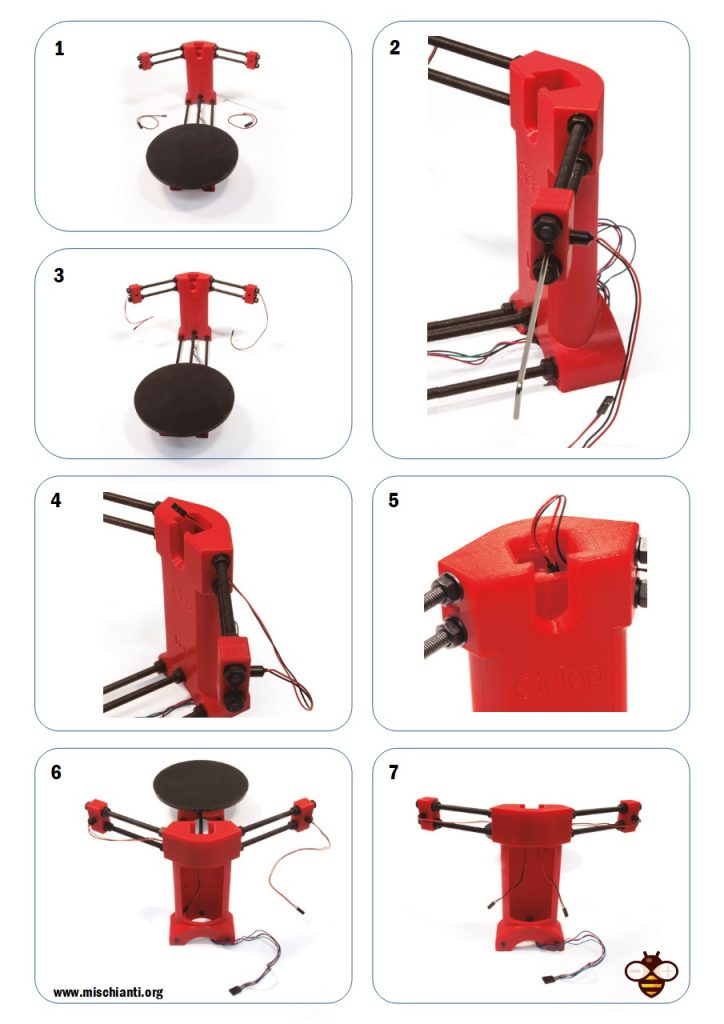
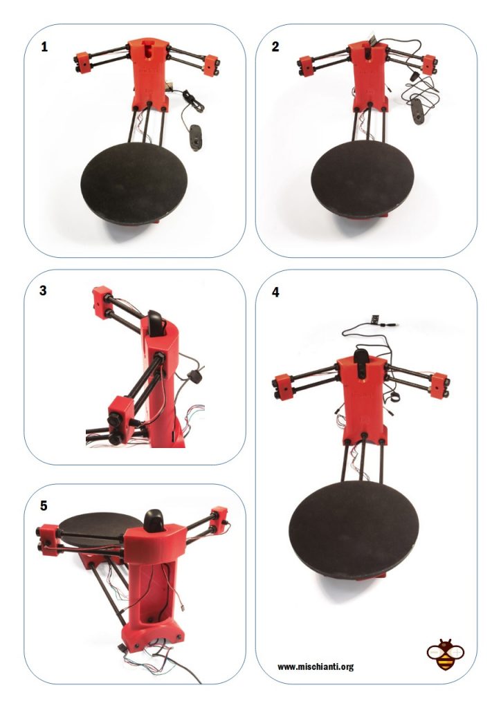
Introduce lasers
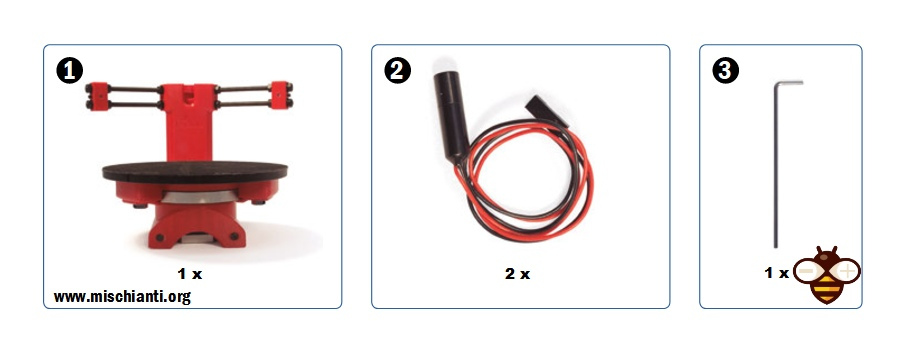
- Assembled structure
- Laser
- Allen wrench
Prepare the camera
Logitech c270 on AliExpress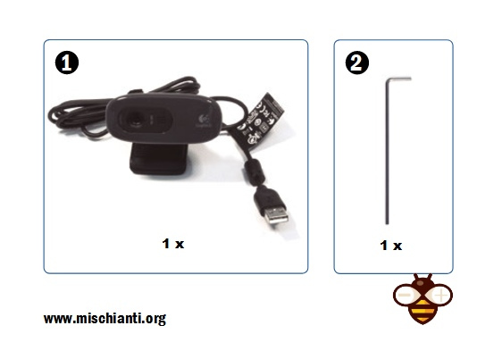
- C270 Logitech® HD Webcam
- Allen wrench
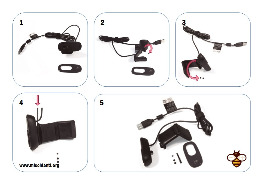
Fit the camera
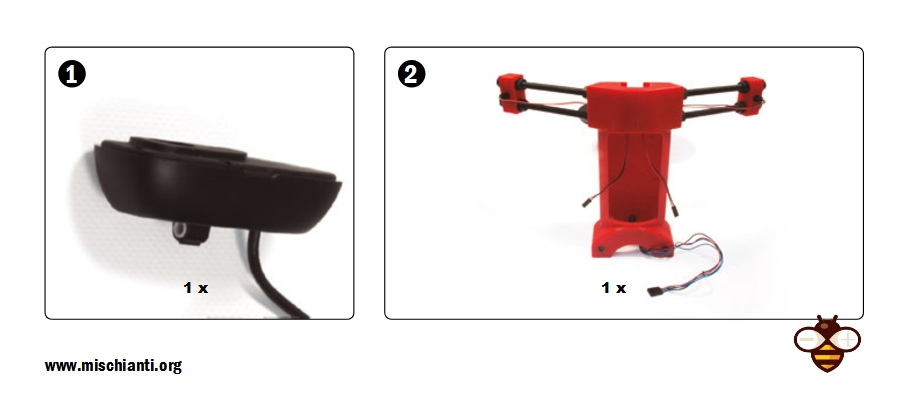
- C270 Logitech® HD Webcam without Add-ons
- Main part assembled
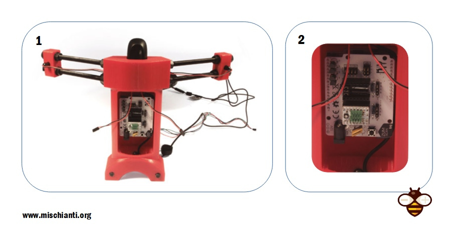
Fit electronics: bq ZUM BT-328 + ZUM SCAN
You can find BQ ZUM Driver Board here Aliexpress
Stepper drivers on AliExpress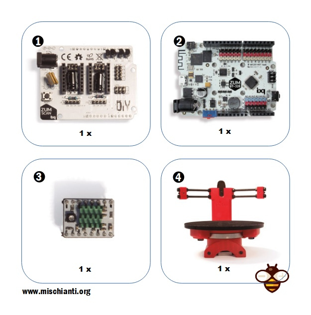
- Bq ZUM SCAN power shield
- Controller board bq ZUM BT-328
- Stepstick Drivers A4988 4 layers
- Main assembled parts
Fit electronics: my PCB
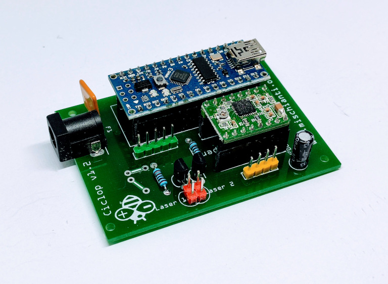
You can get full instruction for my open source PCB (fully ZUM compatible) on the previous article.
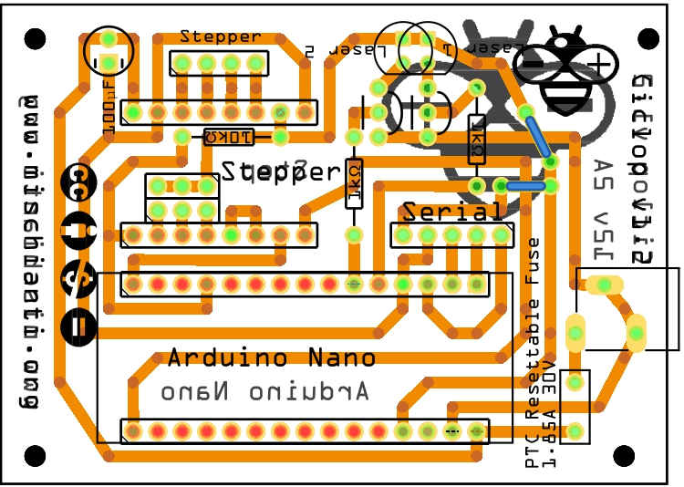
You can order 10 PCB at PCBWay for few dollars here.
Ciclop 3D scanner board v1.2 PCBWay


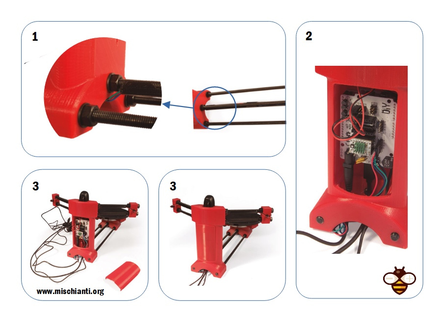
Cable connection and routing
Power supply on Aliexpress 12v
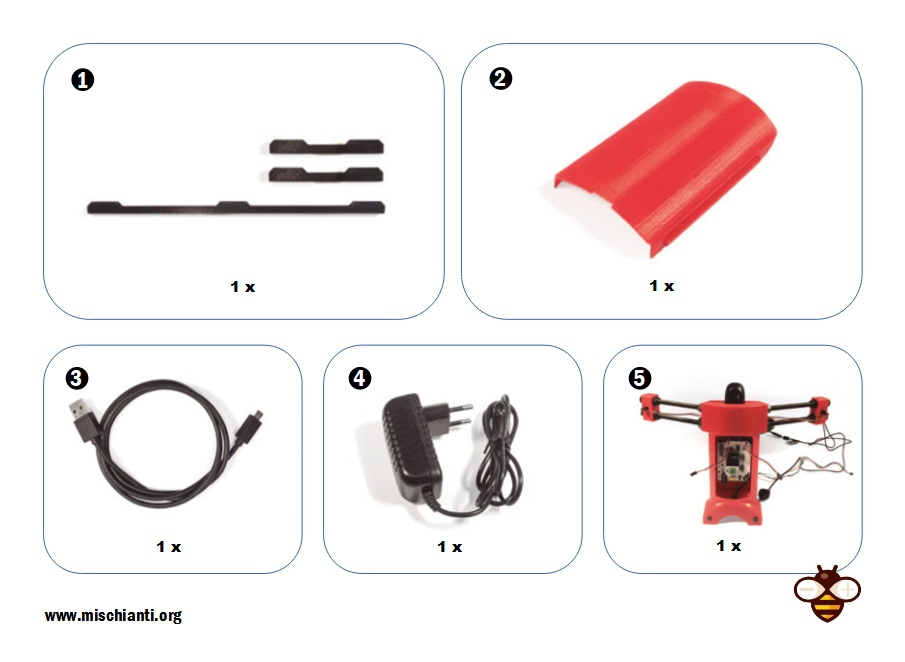
- Printed part for laser cable duct and motor cable duct
- Printed part electronic cover
- Micro-USB cable
- Power supply 12 V 1.5 A
- Main part assembled
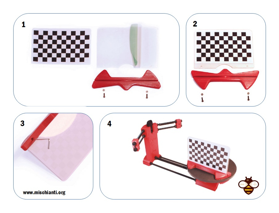
Mounting the calibration pattern

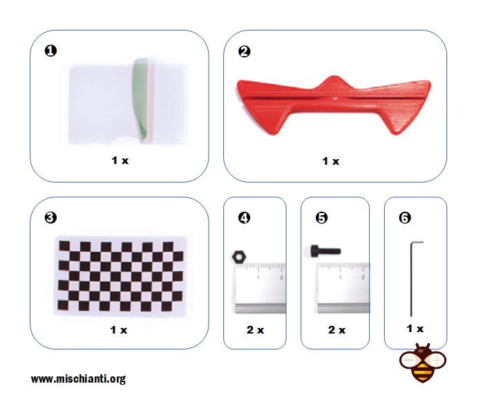
- Methacrylate front pattern
- Checkerboard Sticker
- Printed part pattern support
- Nut M3
- M3 x 10 mm screw
- Allen wrench
Assembling video
Thanks
- Ciclop 3D scanner: component printing and assembly
- Ciclop 3D scanner: production and assembly of the control PCB
- Ciclop 3D scanner: assembling electronic and wiring
- Ciclop 3D scanner: componens testing and calibration


