Exploring the Capabilities of the EByte RF E70 Module (esp32, STM32, Arduino, Raspberry Pi Pico)
The world of wireless communication has been revolutionized by the advent of RF technology, offering a blend of long-range capabilities and low power consumption. The EByte RF E70 module stands out as a prominent player among the various emerging modules. This article delves into the features, applications, and operational modes of the EByte E70, providing insights into its capabilities and potential uses.
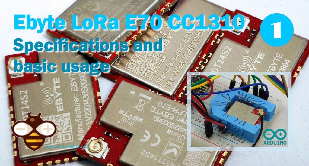
The E70 is based on CC1310 series device. This device is not just a microcontroller (MCU); it is a fully integrated wireless MCU designed specifically for low-power, long-range wireless applications. The CC1310 combines a powerful ARM Cortex-M3 processor with a highly efficient sub-1 GHz radio, making it an ideal solution for a wide range of applications, from smart metering to industrial automation and environmental monitoring.
Introduction to EByte RF E70
The EByte E70 is a RF module designed for long-range wireless communication. It operates in the sub-gigahertz frequency bands, making it ideal for various applications that require long-range communication and low power consumption. Its versatility and efficiency have made it a popular choice in IoT (Internet of Things) applications, smart city projects, and industrial automation.
Key Features of the EByte E70
- Long-Range Communication: The E70 module is known for its exceptional range, capable of transmitting data over several kilometers, depending on environmental conditions.
- Low Power Consumption: It’s optimized for low power usage, extending the battery life of devices, which is crucial for IoT applications.
- Multiple Operation Modes: The E70 supports various modes like transparent mode, fixed mode, continuous mode, and sub-package mode, offering flexibility in different use cases.
- Configurable Parameters: Users can configure parameters like frequency, power output, and data rate, making them adaptable to various communication needs.
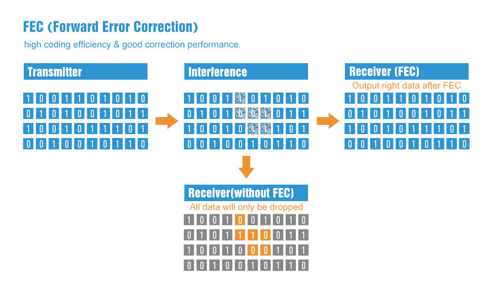
- Forward Error Correction (FEC): FEC is a method for error control in data transmission. It adds redundancy to the transmitted information using a predetermined algorithm. This redundancy allows the receiver to detect and correct errors without the need for retransmission.
Device specifications
- The communication distance tested is up to 1.5/6km
- Maximum transmission power of 1W, software multi-level adjustable;
- Support air date rate of 2.5kbps~168kbps;
- Low power consumption for battery-supplied applications;
- Can achieve up to 115200bps continuous frame unlimited-packet length transmission
- E70-xxxT30S Support 2.6 ~ 5.5V power supply, more than 5V power supply to ensure the best performance;
- E70-xxxT14S/S2 support 2.2 ~ 3.8V power supply, more than 3.3V power supply to ensure the best performance;
- Industrial grade standard design, support -40 ~ 85 °C for working over a long time;
- Support high-speed continuous transmission, send and receive unlimited data packet length;
- Support continuous data frame without packetization, perfect support for ModBus protocol;
- Support custom subcontracting settings to improve communication efficiency;
- Support fixed-point transmission/broadcast transmission/channel monitoring;
- Support RSSI signal strength reading;
- Support over-the-air wake-up, i.e. low-power function, suitable for battery-powered solutions;
- Developed based on CC1310 chip, built-in dual-core ARM;
- Ultra-small volume design;
- Ultra-low receiving current, only about 8mA;
- E70-433 T30S maximum transmit power of 30dBm, the other three models are 25mW, softwaremulti-level adjustable;
- Under ideal conditions, the communication distance can reach 1.5km;
- E70-433T30S built-in PA+LNA, transmission power 1W, communication distance up to 6km;
- Supports the global license-free ISM 433MHz band;
- Support 2.5K~168kbps air transmission rate;
- Support 2.2~3.8V power supply, greater than 3.3V power supply can ensure the best performance;
- E70-433T30S supports 2.6~5.5V power supply , morethan 5V power supply can ensure the best performance;
- Dual antenna optional (IPEX/stamp hole) is convenient for users to develop and facilitate integration.
Transmission Modes
Transparent Mode
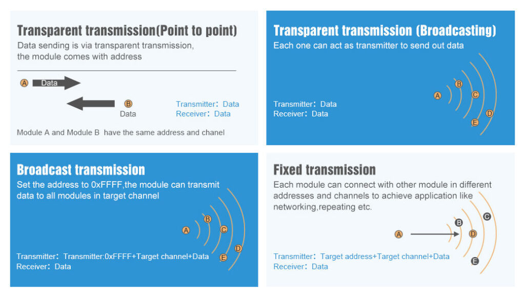
In transparent mode, the E70 module allows for straightforward data transmission, where the data input in one module is exactly output by another, assuming they share the same address and channel.
This can be considered like a “Demo mode”. By default, you can send messages to all devices of the same configured address and channel.
Fixed Mode
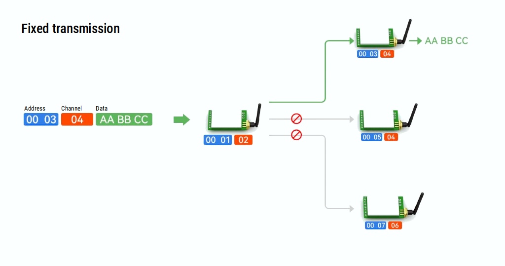
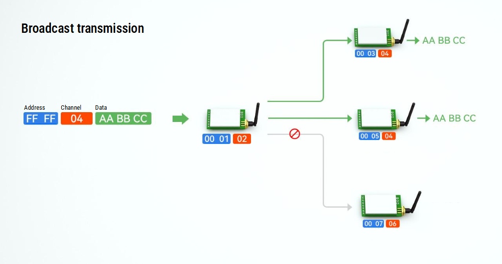
Fixed mode requires data to be sent in a specific format, including the destination address, channel, and hexadecimal data. It’s ideal for structured data communication.
You can select a specified device like in this diagram:
Or to a group of devices identified by the channel:
Variant of transmission
Continuous Mode
Continuous mode is a method of data transmission where the module sends data in a continuous, uninterrupted stream. This mode differs from packet-based transmission, where data is sent in discrete packets. In continuous mode:
- The module continuously transmits data as long as there is data to send.
- It’s typically used in real-time data transmission scenarios, like audio streaming or telemetry.
- This mode can consume more power due to the constant transmission activity.
- It’s effective for applications where latency and timely data delivery are critical.
Continuous mode is ideal for applications that demand a steady data flow without the inherent delays of packet processing and reassembly. However, it requires careful consideration of power management and network bandwidth.
Sub-Package Mode
Sub-packet mode is a data transmission method that divides the data into smaller packets or sub-packets before being sent. In this mode:
- Data is segmented into manageable sizes, making handling easier, especially for larger data sets.
- Each sub-packet is transmitted separately, allowing for better error detection and correction.
- This mode can be more energy-efficient, as the module can enter a low-power state between transmissions.
- It’s suitable for applications where data can be sent intermittently or where data integrity and error handling are more important than real-time transmission.
AUX Pin behavior
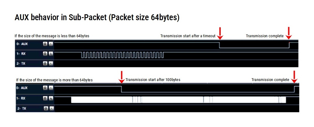
One of the most important things to consider for production solutions is the behavior of the AUX pin. It can be used to optimize the sending performance of managing the wake of external MCU; here are some examples.
Sub-Packet transmission
The diagram begins with the AUX pin in its default inactive state. As the transmission initiates, the image shows the AUX pin activating for each sub-packet sent, followed by a brief return to the inactive state as the module prepares the next sub-packet. This intermittent activation and deactivation pattern is a key feature, highlighting the segmented nature of sub-packet transmission.
Continuous transmission
The diagram highlights the constant active state of the AUX pin as the module transmits data continuously, contrasting it with its behavior in other modes where the AUX pin might change states between packets.

Wake-Up from WOR
The image illustrates a sequential view of the AUX pin transitioning from dormant to active operation. It begins with the AUX pin at a HIGH level, as the wake-up sequence initiates, AUX pin’s transition through HIGH to LOW states, and return HIGH when the message fully received.

RF E70 variants
E70 has various form factors, the design changes, and also specifications.
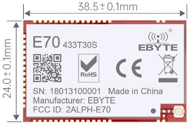
E70-433T30S:
- Logic level voltage: 3.3v and 5v support
- Transmit Power: 30dBm (higher power, capable of longer-distance transmission)
- Receive Sensitivity: -107 to -109 dBm
- Reference Distance: 6000m
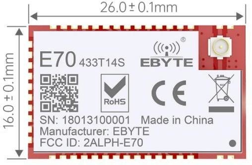
E70-433T14S:
- Logic level voltage: only 3.3v
- Transmit Power: 14dBm (lower power compared to the T30S)
- Receive Sensitivity: -109 to -111 dBm for T14S and -108 dBm for T14S2 (slightly better sensitivity for the T14S)
- Reference Distance: 1500m
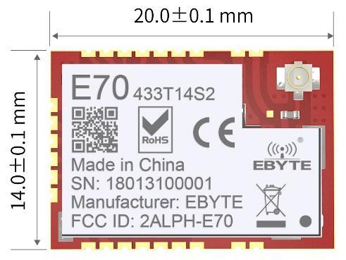
E70-433T14S2:
- Logic level voltage: only 3.3v
- Update of S version.
- Receive Sensitivity: -109 to -111 dBm for T14S and -108 dBm for T14S2 (slightly better sensitivity for the T14S)
- Form factors are simpler to manage.
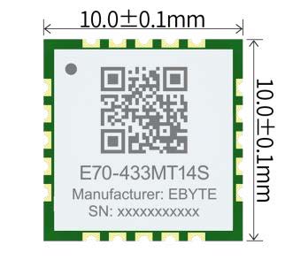
E70-433MT14S:
- Logic level voltage: only 3.3v
- Transmit Power: 14dBm (same as T14S and T14S2)
- Receive Sensitivity: -108 dBm (same as T14S2)
- Reference Distance: 1500m (same as T14S and T14S2)
RF Parameters
| RF parameters | Unit | Model | Remark | |||
|---|---|---|---|---|---|---|
| E70-433T30S | E70-433T14S | E70-433T14S2 | E70-433MT14S | |||
| Transmit power | dBm | 30 | 14 | 14 | 14 | |
| Receive sensitivity | dBm | -107~-109 | -109~-111 | -108 | -108 | The air rate is 2.5kbps |
| Reference distance | M | 6000m | 1500m | 1500m | 1500m | The probability of burning is less when used at close range |
| 5dBi, antenna height 2.5meters, air rate 2.5kbps | ||||||
| Operating frequency band | MHz | 425~450.5 | The factory default is 433MHzand supports the ISM band | |||
| Air velocity | bps | 2.5k~168k | User programmatic control | |||
Blocking power | dBm | 10 | See Transfer Modes for details. | |||
| Launch length | / | The transmission mode is specified | See Transfer Modes for details | |||
Electrical parameter
| Instantaneous power consumption | Unit | Model | Remark | ||||
| E70-433T30S | E70-433T14S | E70-433T14S2 | E70-433MT14S | ||||
| Operating voltage | V | 2.6~5.5 | 2.2~3.8 | 2.2~3.8 | 2.2~3.8 | The software shutdown | |
| Communication level | V | 3.3 | Using 5V TTL carries a risk of burnout | ||||
| Power consumption | Emitted current | mA | 530 | 27 | 36 | 32 | Using 5V TTL carries a risk of burnout |
| Receive current | mA | 14 | 8 | 8 | 9 | ||
| Sleep current | μA | 4 | 1 | 1.2 | 1.7 | Instantaneous power consumption | |
| Temperature | The E70-433T30 Spermanently burns modules over 5.5 V, and the other three models permanently burn modules over 3.8 V. | ℃ | -20~+85 | Industrial grade | |||
| Operating temperature | -40~+125 | ||||||
Hardware parameters
| Hardware parameters | Model | Remark | |||
| E70-433T30S | E70-433T14S | E70-433T14S2 | E70-433MT14S | ||
| Chip | CC1310 | ||||
| Cache capacity | 2048 Byte | User defined | |||
| FLASH | 128 KB | ||||
| RAM | 8 KB | ||||
| Kernel | Cortex-M3(MCU)+Cortex-M0(RF) | ||||
| Communication interface | UART serial port | TTL level | |||
| Modulation method | GFSK | ||||
| Encapsulation method | SMD | ||||
| Antenna interface | IPEX/stamp hole | IPEX/stamp hole | IPEX/stamp hole | Stamp holes | The characteristic impedance is about 50 ohms |
| Size | 24*38.5mm | 16*26 mm | 14 * 20 mm | 10*10mm | The E70-433T14S2 does not include SMA |
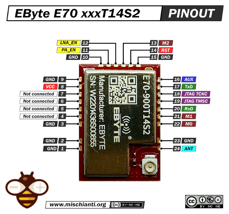
Pinout E70 xxxT14S2
For my test, I’m going to use an E70 S2 version because It’s a comfortable form factor with an onboard SMA antenna.
3D printed socket for breadboard
I created a simple socket with my 3D printer to quickly prototype (and manage) the E70 S2; here is the 3D model and the result on a breadboard.
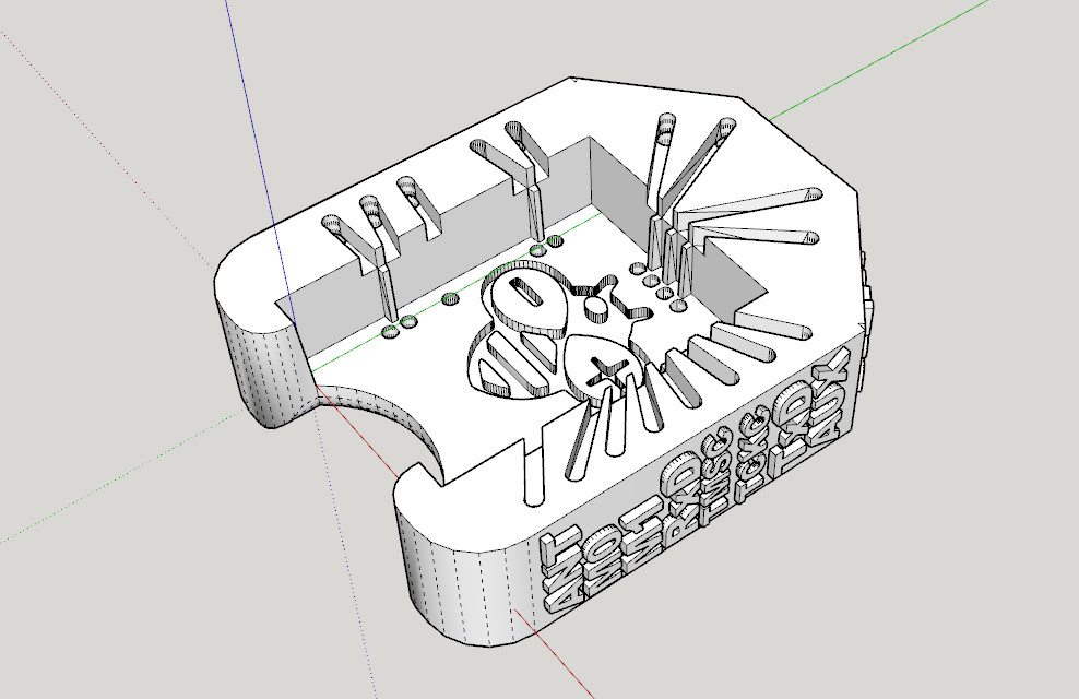
It’s very simple and uses the same technique as other sockets I already created.
After printing, you must add writing inside the hole.
Insert it into the innermost holes and push it out about 3mm
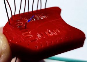
Bend the wire to the external of the adapter.
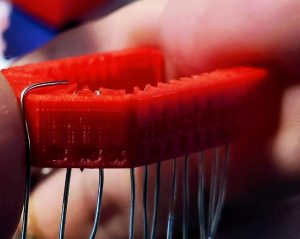
Cut the external part of the wire, and extract,

then reinsert in the internal and external holes.
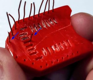
Now check if you need to cut more of the wire of the internal hole and bend It.
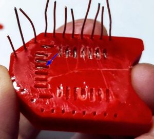
Repeat for all pins. The result It’s very satisfying.
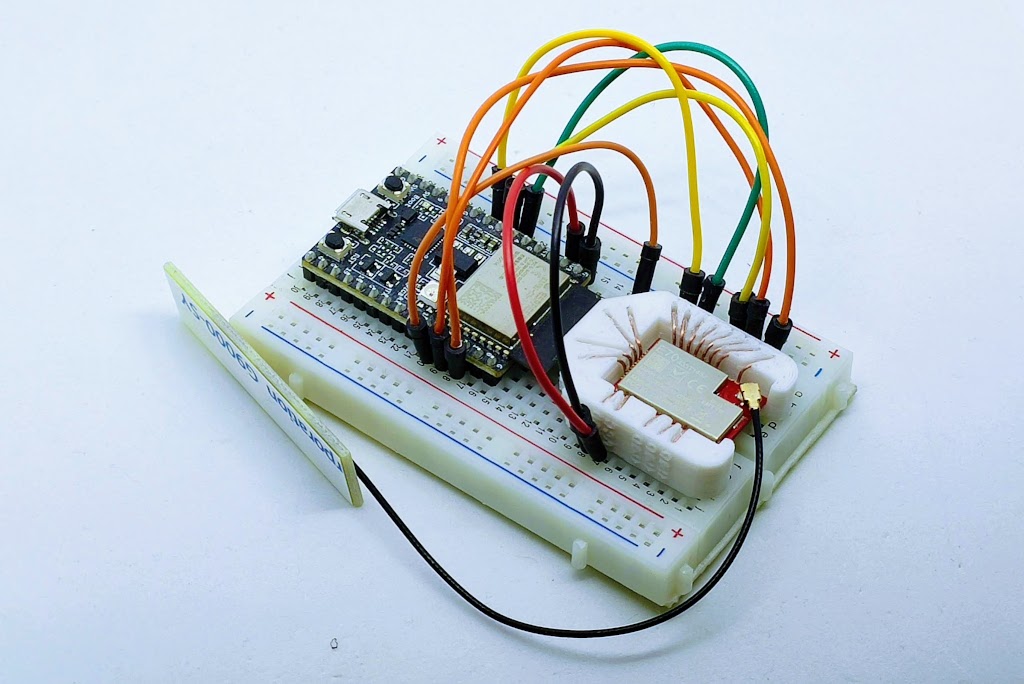
Wiring
The wiring section will be explained better in the next articles.
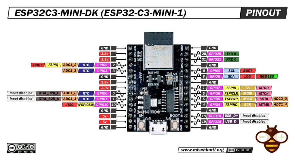
esp32c3
I think one of the most interesting microcontrollers for remote client devices is the esp32c3 series because it is very powerful with low power consumption.
The connection diagram with the socket adapter becomes.
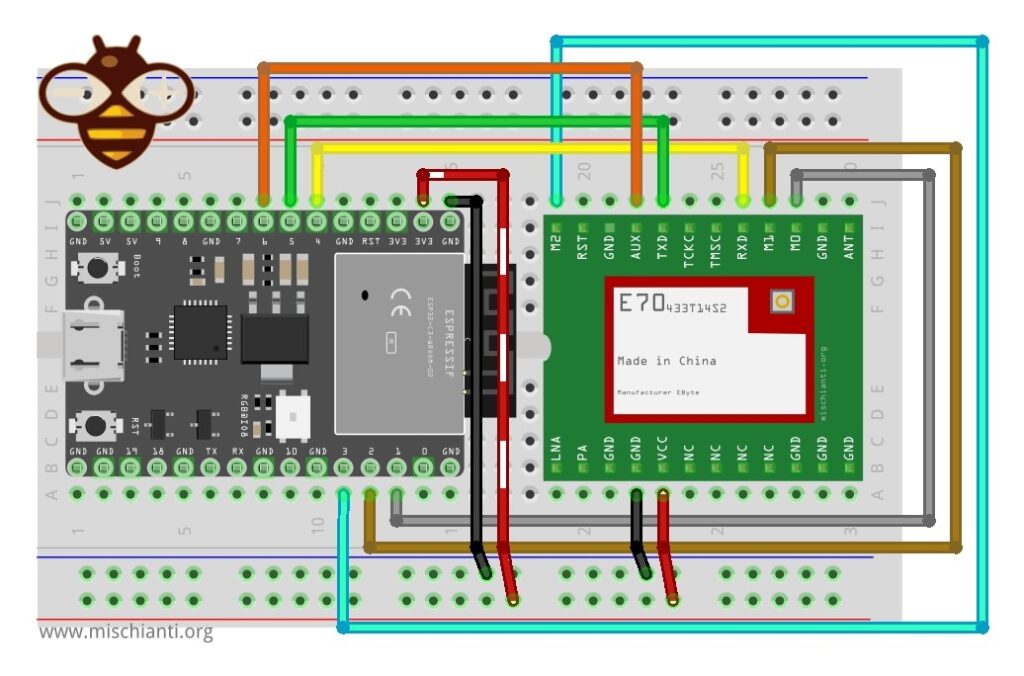
| E70 | ESP32c3 |
|---|---|
| M0 | 1 |
| M1 | 2 |
| M2 | 3 |
| TX | 4 |
| RX | 5 |
| AUX | 6 |
| VCC | 3.3v |
| GND | GND |
Arduino Nano 33 IoT
Onother popular solution is Arduino Nano 33 IoT (probably BLE sense without WiFi It’s a better solution).
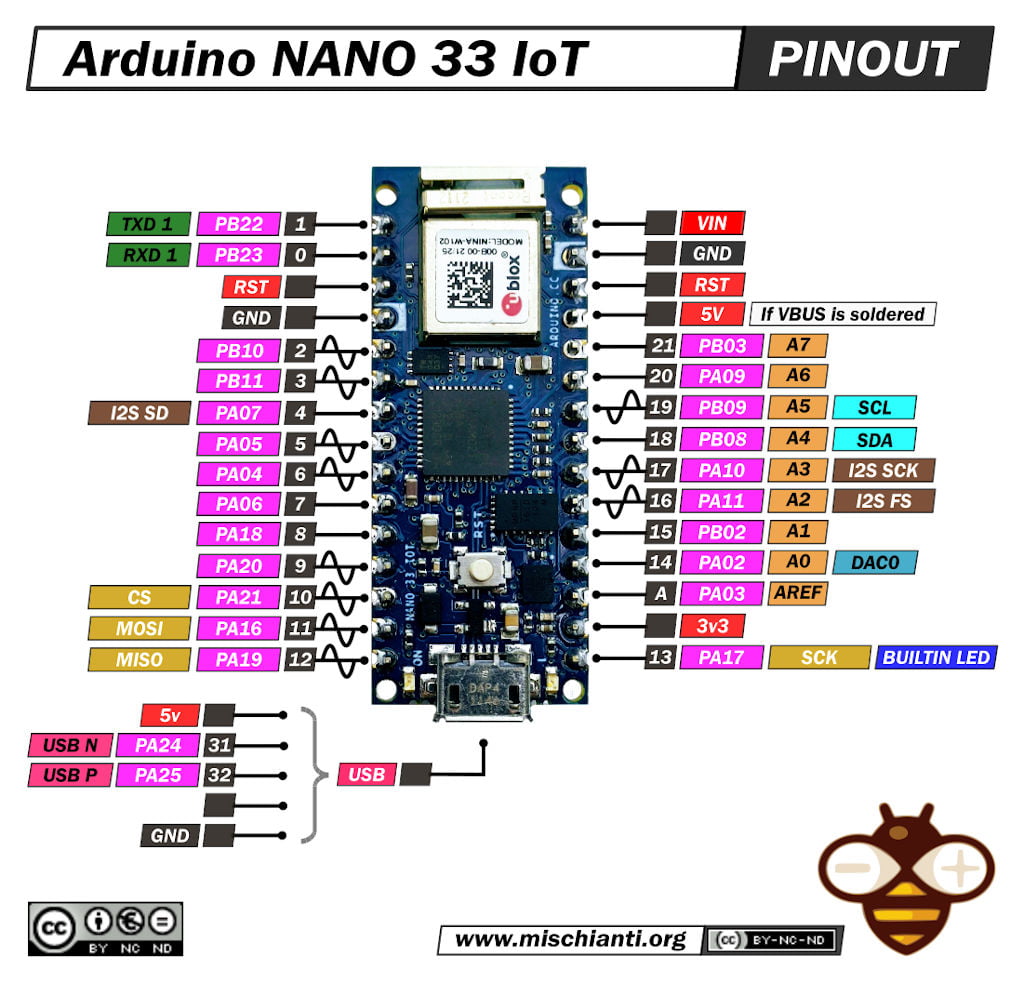
Here the wiring diagram.
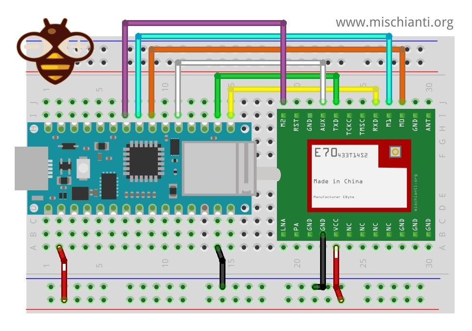
| E70 | Arduino Nano 33 IoT |
|---|---|
| M0 | 4 |
| M1 | 5 |
| M2 | 6 |
| TX | RX1 |
| RX | TX1 |
| AUX | 2 |
| VCC | 3.3v |
| GND | GND |
Raspberry Pi Pico
I don’t like so much but a widely diffused MCU is Raspberry Pi Pico.
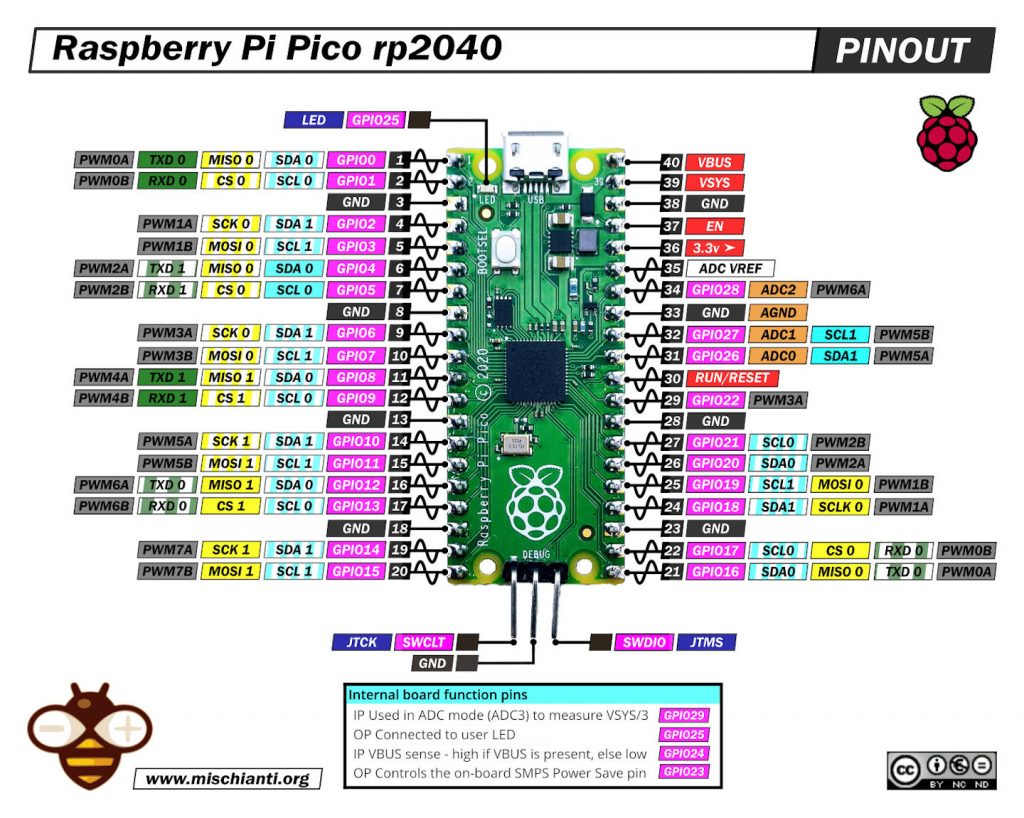
And here the wiring.
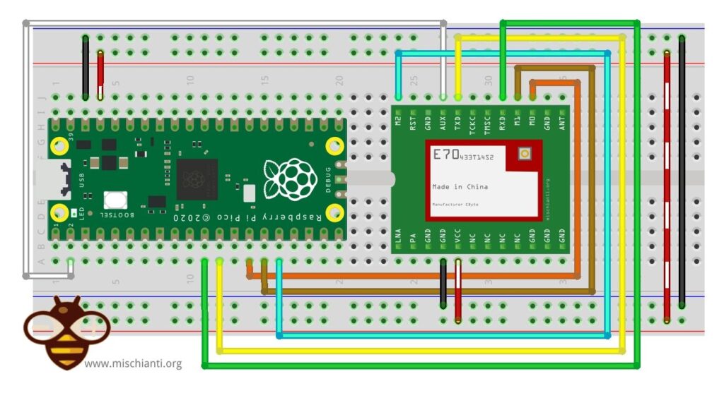
| E70 | rp2040 |
|---|---|
| M0 | 9 |
| M1 | 10 |
| M2 | 11 |
| TX | 8 |
| RX | 9 |
| AUX | 2 |
| VCC | 3.3v |
| GND | GND |
STM32F4
The most powerful and with more features is surely the STM32. It’s without WiFi and probably It’s the best solution.
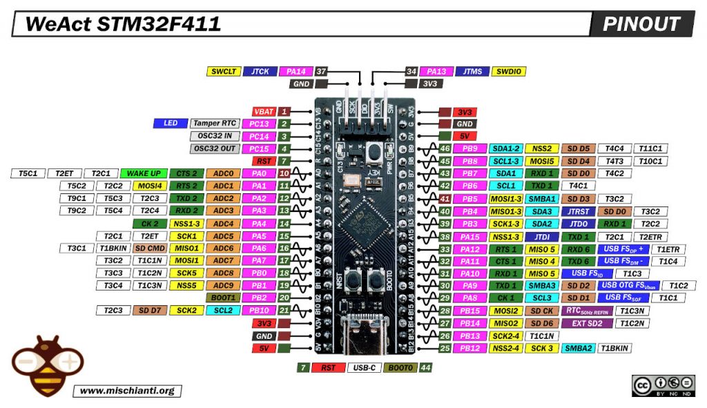
And here the wiring.
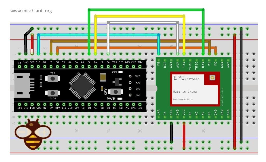
| E70 | STM32 |
|---|---|
| M0 | PB0 |
| M1 | PB1 |
| M2 | PB10 |
| TX | PA2 |
| RX | PA3 |
| AUX | PA0 |
| VCC | 3.3v |
| GND | GND |
Connections note
As you can see, I also connect the M0, M1, and M2, but these are unnecessary; you can select an operation modality by setting these values to those pins.
| Mode (0-7) | M2 | M1 | M0 | Mode introduction | Remark |
|---|---|---|---|---|---|
| 0 RSSI mode | 0 | 0 | 0 | Module outputs RSSI value each 100ms through UART. | The air data rate can be adjusted automatically according to the baud rate. The baud rate must be the same on both the receiver and transmitter. It is applicable for high-speed continuous data transmission. |
| 1 Continuous mode | 0 | 0 | 1 | UART opens. Wireless closes, and sub-package transparent transmission is available. | UART opens. Wireless closes, and continuous transparent transmission is available. |
| 2 Sub-package mode | 0 | 1 | 0 | UART opens. Wireless closes, and parameters can be configured. | Air data rate and baud rate can be adjusted separately. It is applicable for data packet transmission. |
| 3 Configuration mode | 0 | 1 | 1 | The baud rate is fixed as 9600 8N1. | UART opens. Wireless closes, and subpackage transparent transmission is available. |
| 4 WOR mode | 1 | 0 | 0 | Transmission is not available under this mode. It can be woken up by a transmitter under mode 4 to achieve low power consumption receiving. | Receiving is not available under this mode. Preamble code will be added proactively before transmission to wake up the receiver under mode 6. |
| 5 Configuration mode (Same as Mode 3) | 1 | 0 | 1 | – | – |
| 6 Power saving mode | 1 | 1 | 0 | Any M2, M1, or M0 falling edge can wake it up. | UART closes. Wireless works at WOR power saving mode. Multiple-time grades can be configured. |
| 7 Sleep mode | 1 | 1 | 1 | Any falling edge of M2, M1, or M0 can wake it up. | UART closes, wireless transmitting is available, and sleep mode is on. |
For this experiment, you must set the devices in sub-packet mode.
- M0: LOW
- M1: HIGH
- M2: LOW
Send data without library
Naturally, this system is quite limiting, but it isn’t useful for a production system.
Wemos D1 mini sketch
/*
 * RF E70
 * Start device or reset to send a message
 * https://mischianti.org
 *
 * E70       ----- Wemos D1 mini
 * M0         ----- GND
 * M1         ----- HIGH
 * M2         ----- GND
 * TX         ----- PIN D2 (PullUP)
 * RX         ----- PIN D3 (PullUP)
 * AUX        ----- Not connected
 * VCC        ----- 3.3v
 * GND        ----- GND
 *
 */
#include "Arduino.h"
#include <SoftwareSerial.h>

SoftwareSerial mySerial(D3, D4); // e70 TX e32 RX

void setup() {
  Serial.begin(9600);
  delay(500);

  Serial.println("Hi, I'm going to send message!");

  mySerial.begin(9600);
  mySerial.println("Hello, world?");
}

void loop() {
  if (mySerial.available()) {
    Serial.write(mySerial.read());
  }
  if (Serial.available()) {
    mySerial.write(Serial.read());
  }
}
ESP32 sketch
/*
 * RF E70
 * Start device or reset to send a message
 * https://mischianti.org
 *
 * E70        ----- esp32
 * M0         ----- GND
 * M1         ----- HIGH
 * M2         ----- GND
 * TX         ----- RX2 (PullUP)
 * RX         ----- TX2 (PullUP)
 * AUX        ----- Not connected
 * VCC        ----- 3.3v/5v
 * GND        ----- GND
 *
 */
#include "Arduino.h"

void setup() {
  Serial.begin(9600);
  delay(500);

  Serial.println("Hi, I'm going to send message!");

  Serial2.begin(9600);
  Serial2.println("Hello, world?");
}

void loop() {
  if (Serial2.available()) {
    Serial.write(Serial2.read());
  }
  if (Serial.available()) {
    Serial2.write(Serial.read());
  }
}
Arduino SAMD MKR WiFi 1010/Nano 33 IoT
/*
 * RF E70
 * Start device or reset to send a message
 * https://mischianti.org
 *
 * E70        ----- Arduino MKR WiFi 1010
 * M0         ----- GND
 * M1         ----- HIGH
 * M2         ----- GND
 * RX         ----- TX1
 * TX         ----- RX1
 * AUX        ----- Not connected
 * VCC        ----- 3.3v
 * GND        ----- GND
 *
 */
#include "Arduino.h"

void setup() {
  Serial.begin(9600);
  delay(500);

  Serial.println("Hi, I'm going to send message!");

  Serial1.begin(9600);
  Serial1.println("Hello, world?");
}

void loop() {
  if (Serial1.available()) {
    Serial.write(Serial1.read());
  }
  if (Serial.available()) {
    Serial1.write(Serial.read());
  }
}
But this basic usage is quite unuseful, so in the next chapter, we will use my library and go deep into device features.
Library installation
You can find the library on GitHub.
But for simplicity, I added it to the Arduino Library manager.
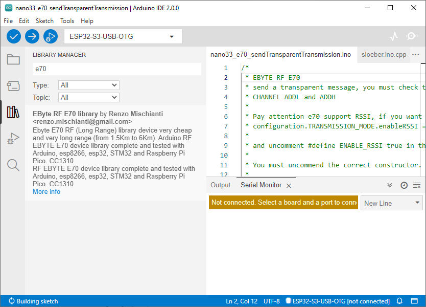
Send data with library
Even if this is a trivial example, we will show how to replicate it with the library. The sketch It’s generic and if you uncomment the correct constructor you can use It for a wide kind of devices.
/*
 * EByte RF E70
 * send a transparent message, you must check that the transmitter and receiver have the same
 * CHANNEL ADDL and ADDH
 *
 * You must uncommend the correct constructor.
 *
 * by Renzo Mischianti <https://www.mischianti.org>
 *
 * https://www.mischianti.org
 *
 * E70		  ----- WeMos D1 mini	----- esp32			----- Arduino Nano 33 IoT	----- Arduino MKR	----- Raspberry Pi Pico   ----- stm32               ----- ArduinoUNO
 * M0         ----- D6 				----- 23 			----- 4 					----- 2 			----- 9 			      ----- PB0 		       	----- 8 Volt div
 * M1         ----- D7 				----- 19 			----- 5 					----- 3 			----- 10 			      ----- PB1 		       	----- 7 Volt div
 * M1         ----- D8 				----- 22 			----- 6 					----- 4 			----- 11 			      ----- PB10 		      	----- 6 Volt div
 * TX         ----- D3 (PullUP)		----- RX2 (PullUP)	----- RX1 (PullUP)			----- 14 (PullUP)	----- 8 (PullUP)	      ----- PA2 RX2 (PullUP)    ----- 4 (PullUP)
 * RX         ----- D4 (PullUP)		----- TX2 (PullUP)	----- TX1 (PullUP)			----- 13 (PullUP)	----- 9 (PullUP)	      ----- PA3 TX2 (PullUP)    ----- 5 Volt div (PullUP)
 * AUX        ----- D5 (PullUP)		----- 18  (PullUP)	----- 2  (PullUP)			----- 0  (PullUP)	----- 2  (PullUP)	      ----- PA0  (PullUP)       ----- 3 (PullUP)
 * VCC        ----- 3.3v/5v			----- 3.3v/5v		----- 3.3v/5v				----- 3.3v/5v		----- 3.3v/5v		      ----- 3.3v/5v             ----- 3.3v/5v
 * GND        ----- GND				----- GND			----- GND					----- GND			----- GND			      ----- GND                 ----- GND
 *
 *	Sub-packet can be emulated by set
 *	M0 = LOW
 *	M1 = HIGH
 *	M2 = LOW
 *	Continuous
 *	M0 = HIGH
 *	M1 = LOW
 *	M2 = LOW
 *
 */

#include "Arduino.h"
#include "RF_E70.h"

// ---------- esp8266 pins --------------
//RF_E70 e70ttl(RX, TX, AUX, M0, M1, M2);  // Arduino RX <-- e70 TX, Arduino TX --> e70 RX
//RF_E70 e70ttl(D3, D4, D5, D7, D6, D7); // Arduino RX <-- e70 TX, Arduino TX --> e70 RX AUX M0 M1
//RF_E70 e70ttl(D2, D3); // Config without connect AUX and M0 M1

//#include <SoftwareSerial.h>
//SoftwareSerial mySerial(D2, D3); // Arduino RX <-- e70 TX, Arduino TX --> e70 RX
//RF_E70 e70ttl(&mySerial, D5, D6, D7, D8); // AUX M0 M1
// -------------------------------------

// ---------- Arduino pins --------------
//RF_E70 e70ttl(4, 5, 3, 8, 7, 6); // Arduino RX <-- e70 TX, Arduino TX --> e70 RX AUX M0 M1
//RF_E70 e70ttl(4, 5); // Config without connect AUX and M0 M1

//#include <SoftwareSerial.h>
//SoftwareSerial mySerial(4, 5); // Arduino RX <-- e70 TX, Arduino TX --> e70 RX
//RF_E70 e70ttl(&mySerial, 3, 8, 7, 6); // AUX M0 M1
// -------------------------------------

// ------------- Arduino Nano 33 IoT -------------
// RF_E70 e70ttl(&Serial1, 2, 4, 5, 6); //  RX AUX M0 M1
// -------------------------------------------------

// ------------- Arduino MKR WiFi 1010 -------------
// RF_E70 e70ttl(&Serial1, 0, 2, 3, 4); //  RX AUX M0 M1
// -------------------------------------------------

// ---------- esp32c3 pins --------------
// RF_E70 e70ttl(&Serial1,  1, 2, 3, 4,); //  RX AUX M0 M1

RF_E70 e70ttl(4, 5, &Serial1, 6, 1, 2, 3, UART_BPS_RATE_9600); //  esp32 RX <-- e70 TX, esp32 TX --> e70 RX AUX M0 M1
// -------------------------------------

// ---------- esp32 pins --------------
// RF_E70 e70ttl(&Serial2, 15, 23, 19, 22); //  RX AUX M0 M1

//RF_E70 e70ttl(&Serial2, 22, 4, 18, 21, 19, UART_BPS_RATE_9600); //  esp32 RX <-- e70 TX, esp32 TX --> e70 RX AUX M0 M1
// -------------------------------------

// ---------- Raspberry PI Pico pins --------------
// RF_E70 e70ttl(&Serial2, 2, 10, 11, 12); //  RX AUX M0 M1
// -------------------------------------

// ---------------- STM32 --------------------
// HardwareSerial Serial2(USART2);   // PA3  (RX)  PA2  (TX)
// RF_E70 e70ttl(&Serial2, PA0, PB0, PB1, PB10); //  RX AUX M0 M1
// -------------------------------------------------

 void setup() {
  Serial.begin(9600);
#if defined(ARDUINO_ARCH_STM32) || defined(__STM32F1__) || defined(__STM32F4__)
	Serial.dtr(false);
#endif

  delay(500);

  // Startup all pins and UART
  e70ttl.begin();

//  e70ttl.setMode(MODE_CONTINUOUS_1);

//  If you have ever change configuration you must restore It

  Serial.println("Hi, I'm going to send message!");
  // Send message
  ResponseStatus rs = e70ttl.sendMessage("Hello, world?");
  // Check If there is some problem of succesfully send
  Serial.println(rs.getResponseDescription());
}

void loop() {
	// If something available
  if (e70ttl.available()>1) {
	  // read the String message
	ResponseContainer rc = e70ttl.receiveMessage();
	// Is something goes wrong print error
	if (rc.status.code!=1){
		Serial.println(rc.status.getResponseDescription());
	}else{
		// Print the data received
		Serial.println(rc.status.getResponseDescription());
		Serial.println(rc.data);
	}
  }
  if (Serial.available()) {
	  String input = Serial.readString();
	  e70ttl.sendMessage(input);
  }
}
Thanks
- EByte RF E70 433/868/900 T14S2: pinout, datasheet and specs (1.5Km)
- EByte RF E70 Module Adapter: PCB, 3D Printed, Breadboard-Friendly Solution and configuration
- Connecting the EByte E70 to ESP32 c3/s3 devices and a simple sketch example
- Connecting the EByte E70 to Arduino SAMD (Nano 33, MKR…) devices and a simple sketch example
- Connecting the EByte E70 to STM32 (black/blue pill) devices and a simple sketch example
- Connecting the EByte E70 to Raspberry Pi Pico (rp2040) devices and a simple sketch example
- Exploring the Capabilities of the EByte RF E70 Module (esp32, STM32, Arduino, Raspberry Pi Pico)
- EByte RF E70 CC1310: exploring library (esp32, esp8266, STM32, Arduino, Raspberry Pi Pico)
- Configuration of EByte RF E70 Module (esp32, STM32, Arduino, Raspberry Pi Pico)


