Ebyte LoRa E32 device for Arduino, esp32 or esp8266: specs and basic use – 1
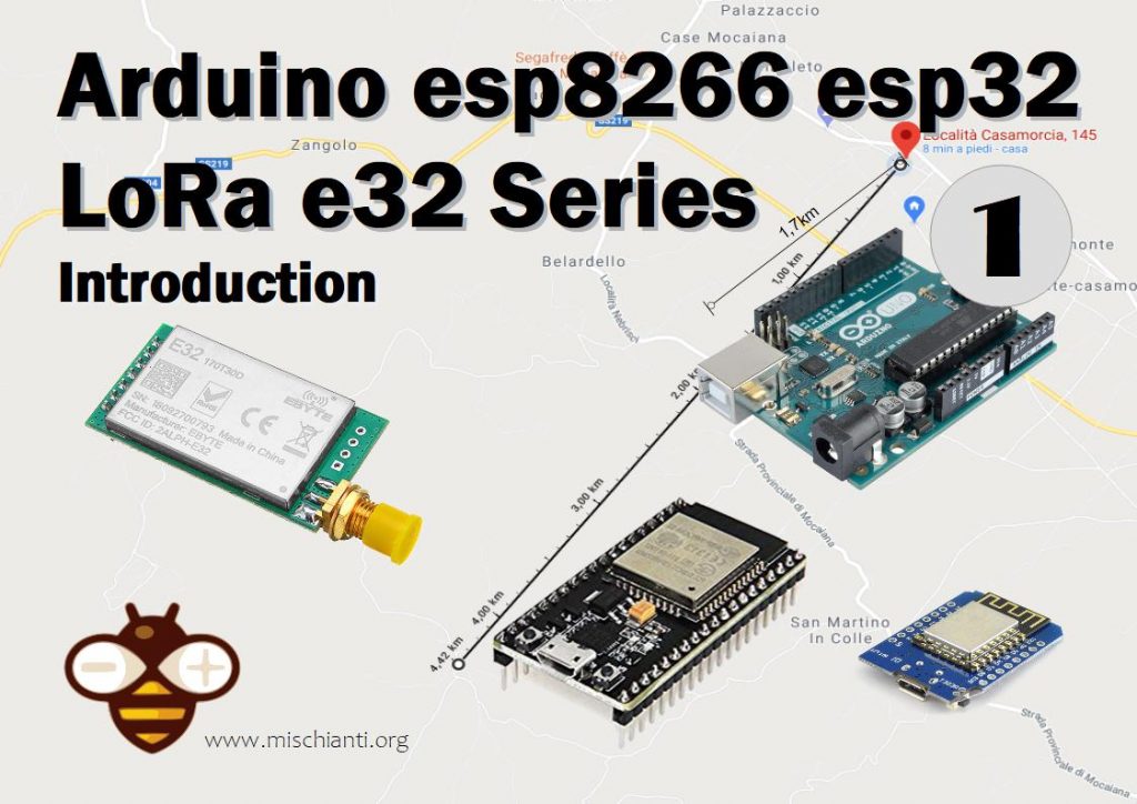
LoRa or Long Range wireless data telemetry is a technology pioneered by Semtech that operates at a lower frequency than NRF24L01 (433 MHz, 868 MHz, or 916 MHz against 2.4 GHz for the NRF24L01) but at thrice the distance (from 3000m to 8000m).
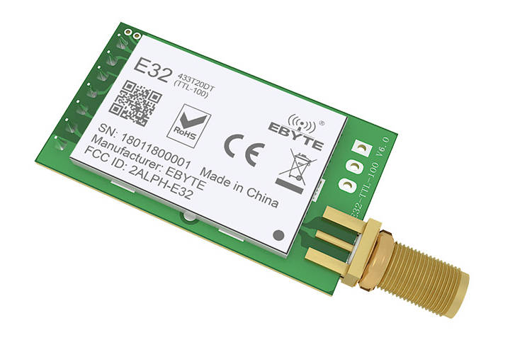
You can find here AliExpress (433MHz 5Km) - AliExpress (433MHz 8Km) - AliExpress (433MHz 16Km) - AliExpress (868MHz 915MHz 5.5Km) - AliExpress (868MHz 915MHz 8Km)
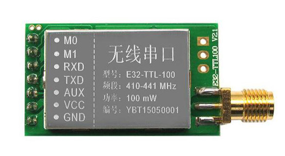
We are going to test E32-TTL-100. It is a wireless transceiver module, operates at 410 441 MHz based on original RFIC SX1278 from SEMTECH, transparent transmission is available, TTL level. The module adopts LORA spread spectrum technology.
The module features FEC Forward Error Correction algorithm, which ensure its high coding efficiency & good correction performance. In the case of sudden interference, it can correct the interfered data packets automatically, so that the reliability and transmission range are improved correspondingly. But without FEC, those da te packets can only be dropped.
And with the rigorous encryption & decryption, data interception becomes pointless. The function of data compression can decrease the transmission time & probability of being interference, while improving the reliability & transmission efficiency.
Operating and transmission type
This device have some interesting function:
Transmission
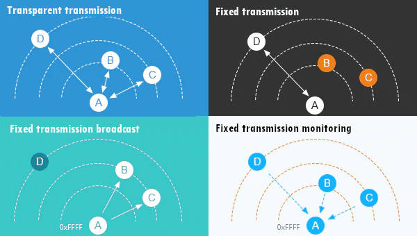
Transparent transmission
This can be considered like a “Demo mode”, by default you can send message to all device of same configured address and channel.
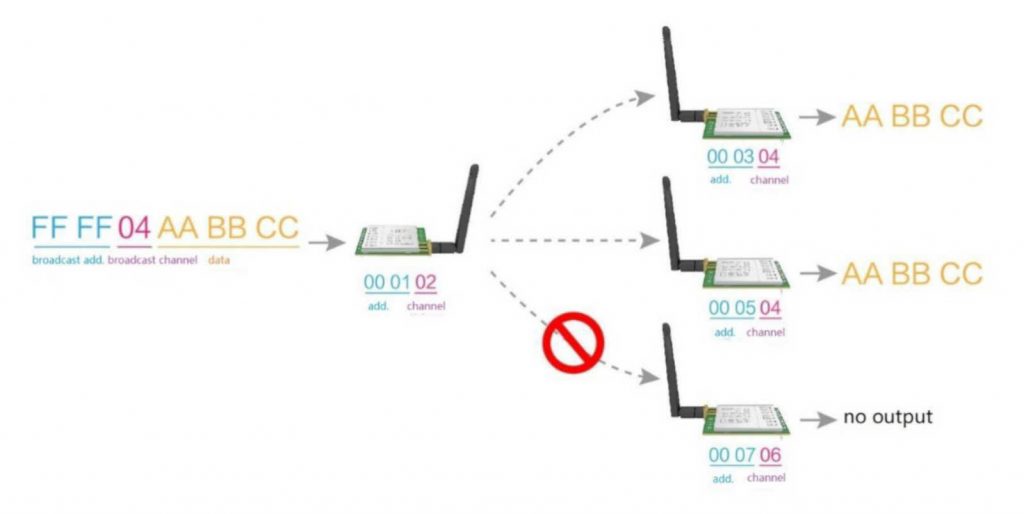
Fixed transmission
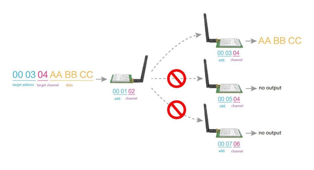
This type of transmission you can specify an address and a channel where where you want send the message.
You can send message to a:
- Specified device with a predeterminated Address Low, Address High and Channel.
- Broadcast a message on predeterminated Channel.
Normal mode
Simply send message.
Wake-up mode and power-saving mode
As you can intend if a device is in Wake-up mode can “wake” one or more devices that are in power-saving mode with a preamble communication.
Program/sleep mode
With this configuration you can change configuration of your device.
Specifications
Here’s the specifications for the module:
- Module size: 21*36mm
- Antenna type: SMA-K (50Ω impedance)
- Transmission distance: 3000m(max)
- Maximum power: 2dB(100mW)
- Air rates: 2.4Kbps (6 optional level (0.3, 1.2, 2.4, 4.8, 9.6, 19.2kbps)
- Emission length: 512Byte
- Receive length: 512Byte
- Communication Interface: UART – 8N1, 8E1, 8O1, Eight kinds of UART baud Rate, from 1200 to 115200bps (Default: 9600)
- RSSI support: No (Built-in intelligent processing)
- Working frequency: 410MHz-441MHz (Default 433MHz), Channel: 32
| Electronic parameter | Min. | Typ. | Max. | Unit |
|---|---|---|---|---|
| Power supply | 2.3 | 3.3 | 5.5 | V |
| Communication level | 3.0 | 3.3 | 3.6 | V |
| Transmitting current | 102 | 110 | 118 | mA |
| Receiving current | 12 | 15 | 18 | mA |
| Sleep current | 3 | 5 | 8 | μA |
| Operating temperature | -40 | 20 | +85 | ℃ |
| Operating humidity | 10 | 60 | 90 | % |
| Storage temperature | -40 | 20 | +125 | ℃ |
You must pay attention on communication level that differ from power supply, the second can receive voltage like 3.3v (esp8266 and esp32) and 5v (Arduino), but the first want a 3.3v, so to connecto to an Arduino you must use a Voltage divider (Voltage divider: calculator and application) to prevent damage to the device.
Pinout
| Pin No. | Pin item | Pin direction | Pin application |
|---|---|---|---|
| 1 | M0 | Input(weak pull-up) | Work with M1 & decide the four operating modes.Floating is not allowed, can be ground. |
| 2 | M1 | Input(weak pull-up) | Work with M0 & decide the four operating modes.Floating is not allowed, can be ground. |
| 3 | RXD | Input | TTL UART inputs, connects to external (MCU, PC) TXD outputpin. Can be configured as open-drain or pull-up input. |
| 4 | TXD | Output | TTL UART outputs, connects to external RXD (MCU, PC) inputpin. Can be configured as open-drain or push-pull output |
5 | AUX | Output | To indicate module’s working status & wakes up the external MCU. During the procedure of self-check initialization, the pin outputs low level. Can be configured as open-drain output orpush-pull output (floating is allowed). |
| 6 | VCC | Power supply 2.3V~5.5V DC | |
| 7 | GND | Ground |
As you can see you can set various modes via M0 and M1 pins.
| Mode | M1 | M0 | Explanation |
|---|---|---|---|
| Normal | 0 | 0 | UART and wireless channel is good to go |
| Wake-Up | 0 | 1 | Same as normal but a preamble code is added to transmitted data for waking-up the receiver. |
| Power-Saving | 1 | 0 | UART is disable and wireless is on WOR(wake on radio) mode which means the device will turn on when there is data to be received. Transmission is not allowed. |
| Sleep | 1 | 1 | Used in setting parameters. Transmitting and receiving disabled. |
For the next simple test we are going to use Normal mode.
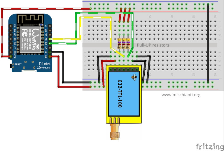
Connecting Wemos D1 mini (esp8266) for a basic usage
esp8266 have the advantage to have same voltage of communication interface so the connection schema is more simple than Arduino.
It’s important to add pull-up resistor (4,7Kohm) to get good stability.
| M0 | GND (Set normal mode) |
| M1 | GND (Set normal mode) |
| RX | PIN D2 (PullUP 4,7KΩ) |
| TX | PIN D3 (PullUP 4,7KΩ) |
| AUX | Not connected |
| VCC | 3.3v |
| GND | GND |
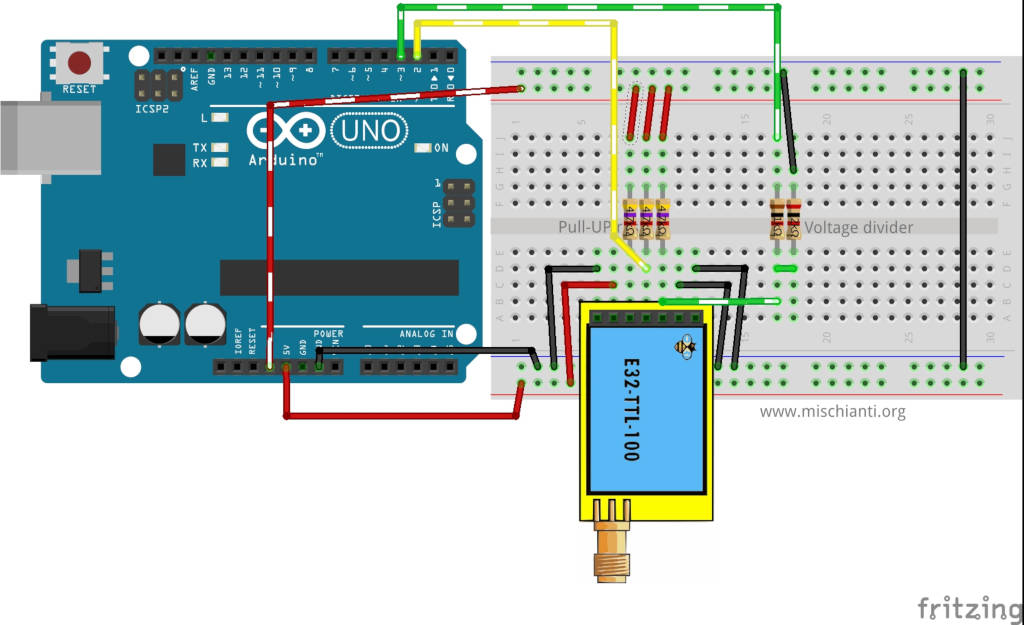
Connecting Arduino for a basic usage
Arduino working voltage is 5v, so we need to add a voltage divider on RX pin of LoRa module to prevent damage, you can get more information here Voltage divider: calculator and application.
You can use a 2Kohm resistor to GND and 1Kohm from signal than put together on RX.
| M0 | GND (Set normal mode) |
| M1 | GND (Set normal mode) |
| RX | PIN D2 (PullUP 4,7KΩ & Voltage divider) |
| TX | PIN D3 (PullUP 4,7KΩ) |
| AUX | Not connected |
| VCC | 3.3v |
| GND | GND |
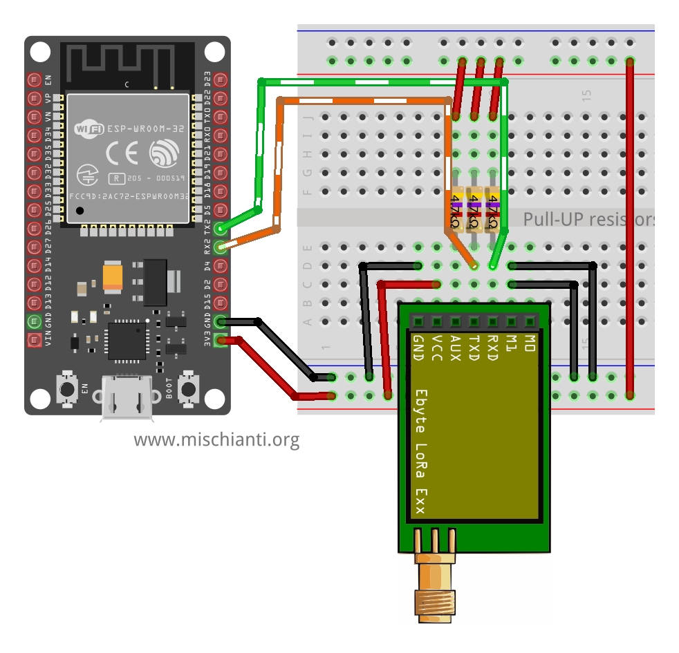
Connecting ESP-32 for a basic usage
| M0 | GND (Set normal mode) |
| M1 | GND (Set normal mode) |
| RX | TX2 (PullUP 4,7KΩ) |
| TX | RX2 (PullUP 4,7KΩ) |
| AUX | Not connected |
| VCC | 3.3v-5v |
| GND | GND |
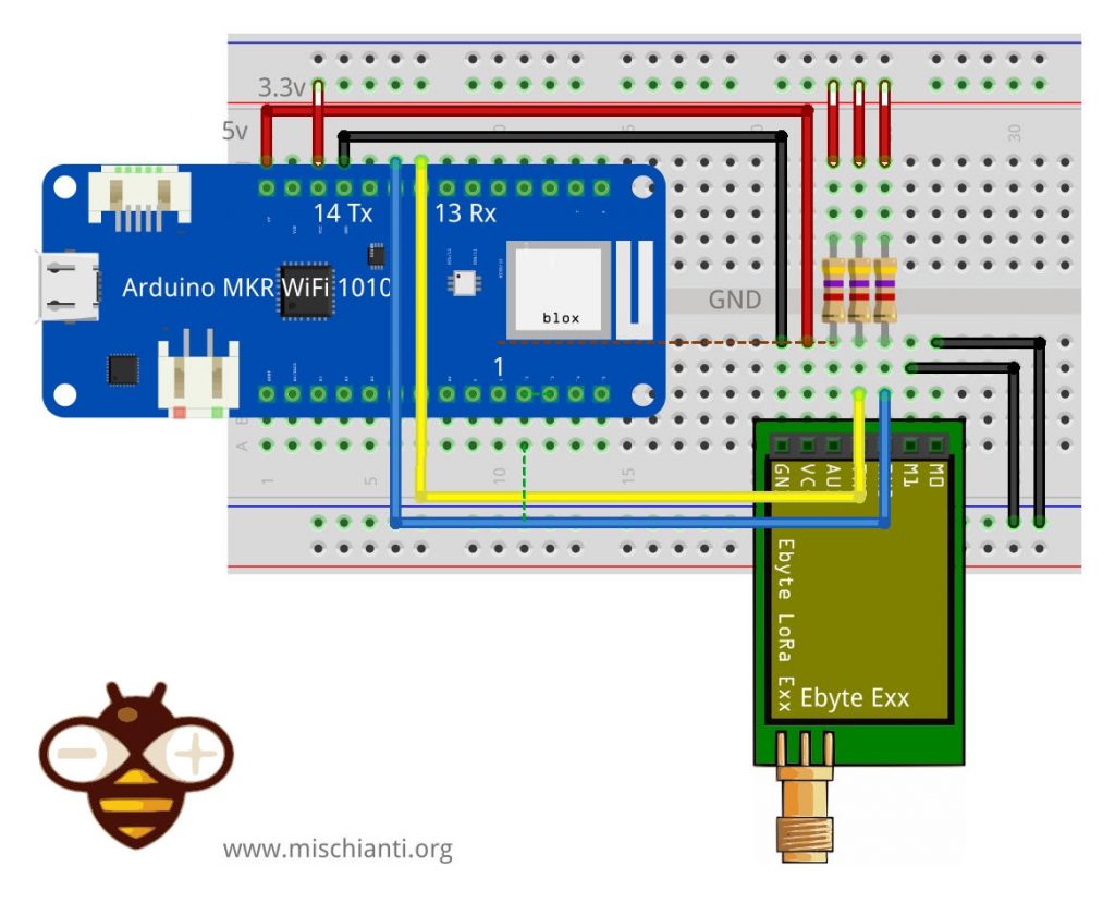
Connecting Arduino SAMD MKR WiFi 1010 for a basic usage
| M0 | GND (Set normal mode) |
| M1 | GND (Set normal mode) |
| TX | PIN 14 Tx (PullUP 4,7KΩ) |
| RX | PIN 13 Rx (PullUP 4,7KΩ) |
| AUX | PIN 1 (PullUP 4,7KΩ) |
| VCC | 5V |
| GND | GND |
Simple communication sketch
If you put 0 M1 and M0 pins, you enter “Normal” mode, and then you can receive and transmit all the data from device A to B; this modality is defined as “Transparent transmission”.
You can use 2 Arduinos or 2 Wemos D1 mini or one of a kind.
At the start, send a message, and if you write on a serial from one of the devices, the text is transferred to the other device. You can use 2 Arduinos or 2 Wemos or one and one, as you prefer.
Arduino sketch
/*
 * LoRa E32-TTL-100
 * Start device or reset to send a message
 * https://mischianti.org
 *
 * E32-TTL-100----- Arduino UNO
 * M0         ----- GND
 * M1         ----- GND
 * TX         ----- PIN 2 (PullUP)
 * RX         ----- PIN 3 (PullUP & Voltage divider)
 * AUX        ----- Not connected
 * VCC        ----- 3.3v/5v
 * GND        ----- GND
 *
 */
#include "Arduino.h"

#include <SoftwareSerial.h>

SoftwareSerial mySerial(2, 3); // e32 TX e32 RX

void setup() {
  Serial.begin(9600);
  delay(500);

  Serial.println("Hi, I'm going to send message!");

  mySerial.begin(9600);
  mySerial.println("Hello, world?");
}

void loop() {
  if (mySerial.available()) {
    Serial.write(mySerial.read());
  }
  if (Serial.available()) {
    mySerial.write(Serial.read());
  }
}
Wemos D1 mini sketch
/*
 * LoRa E32-TTL-100
 * Start device or reset to send a message
 * https://mischianti.org
 *
 * E32-TTL-100----- Wemos D1 mini
 * M0         ----- GND
 * M1         ----- GND
 * TX         ----- PIN D2 (PullUP)
 * RX         ----- PIN D3 (PullUP)
 * AUX        ----- Not connected
 * VCC        ----- 3.3v/5v
 * GND        ----- GND
 *
 */
#include "Arduino.h"
#include <SoftwareSerial.h>

SoftwareSerial mySerial(D2, D3); // e32 TX e32 RX

void setup() {
  Serial.begin(9600);
  delay(500);

  Serial.println("Hi, I'm going to send message!");

  mySerial.begin(9600);
  mySerial.println("Hello, world?");
}

void loop() {
  if (mySerial.available()) {
    Serial.write(mySerial.read());
  }
  if (Serial.available()) {
    mySerial.write(Serial.read());
  }
}
ESP32 sketch
/*
 * LoRa E32
 * Start device or reset to send a message
 * https://mischianti.org
 *
 * E32        ----- esp32
 * M0         ----- GND
 * M1         ----- GND
 * TX         ----- RX2 (PullUP)
 * RX         ----- TX2 (PullUP)
 * AUX        ----- Not connected
 * VCC        ----- 3.3v/5v
 * GND        ----- GND
 *
 */
#include "Arduino.h"

void setup() {
  Serial.begin(9600);
  delay(500);

  Serial.println("Hi, I'm going to send message!");

  Serial2.begin(9600);
  Serial2.println("Hello, world?");
}

void loop() {
  if (Serial2.available()) {
    Serial.write(Serial2.read());
  }
  if (Serial.available()) {
    Serial2.write(Serial.read());
  }
}
Arduino SAMD MKR WiFi 1010
/*
 * LoRa E32
 * Start device or reset to send a message
 * https://mischianti.org
 *
 * E32        ----- Arduino MKR WiFi 1010
 * M0         ----- 2 (or GND)
 * M1         ----- 3 (or GND)
 * RX         ----- 14 (PullUP)
 * TX         ----- 13 (PullUP)
 * AUX        ----- 1  (PullUP)
 * VCC        ----- 3.3v/5v
 * GND        ----- GND
 *
 */
#include "Arduino.h"

void setup() {
  Serial.begin(9600);
  delay(500);

  Serial.println("Hi, I'm going to send message!");

  Serial1.begin(9600);
  Serial1.println("Hello, world?");
}

void loop() {
  if (Serial1.available()) {
    Serial.write(Serial1.read());
  }
  if (Serial.available()) {
    Serial1.write(Serial.read());
  }
}
But this basic usage is quite unusefully, so in the next chapter we are going to use my library and go in deep of device features.
Library
Here the last example with my library:
Arduino sketch
/*
 * LoRa E32-TTL-100
 * Write on serial to transfer a message to other device
 * https://mischianti.org
 *
 * E32-TTL-100----- Arduino UNO
 * M0         ----- GND
 * M1         ----- GND
 * TX         ----- PIN 2 (PullUP)
 * RX         ----- PIN 3 (PullUP & Voltage divider)
 * AUX        ----- Not connected
 * VCC        ----- 3.3v/5v
 * GND        ----- GND
 *
 */
#include "Arduino.h"
#include "LoRa_E32.h"

LoRa_E32 e32ttl100(2, 3); // e32 TX e32 RX

void setup() {
  Serial.begin(9600);
  delay(500);

  Serial.println("Hi, I'm going to send message!");

  // Startup all pins and UART
  e32ttl100.begin();

  // Send message
  ResponseStatus rs = e32ttl100.sendMessage("Hello, world?");
  // Check If there is some problem of successfully send
  Serial.println(rs.getResponseDescription());
}

void loop() {
	// If something available
  if (e32ttl100.available()>1) {
	  // read the String message
	ResponseContainer rc = e32ttl100.receiveMessage();
	// Is something goes wrong print error
	if (rc.status.code!=1){
		rc.status.getResponseDescription();
	}else{
		// Print the data received
		Serial.println(rc.data);
	}
  }
  if (Serial.available()) {
	  String input = Serial.readString();
	  e32ttl100.sendMessage(input);
  }
}
Here the Wemos D1 (esp8266) sketch
/*
 * LoRa E32-TTL-100
 * Start device or reset to send a message
 * https://mischianti.org
 *
 * E32-TTL-100----- Wemos D1 mini
 * M0         ----- GND
 * M1         ----- GND
 * TX         ----- PIN D2 (PullUP)
 * RX         ----- PIN D3 (PullUP)
 * AUX        ----- Not connected
 * VCC        ----- 3.3v/5v
 * GND        ----- GND
 *
 */
#include "Arduino.h"
#include "LoRa_E32.h"

LoRa_E32 e32ttl100(D2, D3); // e32 TX e32 RX

void setup() {
  Serial.begin(9600);
  delay(500);

  Serial.println("Hi, I'm going to send message!");

  // Startup all pins and UART
  e32ttl100.begin();

  // Send message
  ResponseStatus rs = e32ttl100.sendMessage("Hello, world?");
  // Check If there is some problem of successfully send
  Serial.println(rs.getResponseDescription());
}

void loop() {
	// If something available
  if (e32ttl100.available()>1) {
	  // read the String message
	ResponseContainer rc = e32ttl100.receiveMessage();
	// Is something goes wrong print error
	if (rc.status.code!=1){
		rc.status.getResponseDescription();
	}else{
		// Print the data received
		Serial.println(rc.data);
	}
  }
  if (Serial.available()) {
	  String input = Serial.readString();
	  e32ttl100.sendMessage(input);
  }
}
ESP-32 sketch
/*
 * EBYTE LoRa E32
 * send a transparent message, you must check that the transmitter and receiver have the same
 * CHANNEL ADDL and ADDH
 *
 *
 * https://mischianti.org
 *
 * E32		  ----- esp32
 * M0         ----- 19 (or GND)
 * M1         ----- 21 (or GND)
 * RX         ----- TX2 (PullUP)
 * TX         ----- RX2 (PullUP)
 * AUX        ----- 15  (PullUP)
 * VCC        ----- 3.3v/5v
 * GND        ----- GND
 *
 */

#include "Arduino.h"
#include "LoRa_E32.h"

// ---------- esp8266 pins --------------
//LoRa_E32 e32ttl(RX, TX, AUX, M0, M1);  // Arduino RX <-- e22 TX, Arduino TX --> e22 RX
//LoRa_E32 e32ttl(D3, D4, D5, D7, D6); // Arduino RX <-- e22 TX, Arduino TX --> e22 RX AUX M0 M1
//LoRa_E32 e32ttl(D2, D3); // Config without connect AUX and M0 M1

//#include <SoftwareSerial.h>
//SoftwareSerial mySerial(D2, D3); // Arduino RX <-- e22 TX, Arduino TX --> e22 RX
//LoRa_E32 e32ttl(&mySerial, D5, D7, D6); // AUX M0 M1
// -------------------------------------

// ---------- Arduino pins --------------
//LoRa_E32 e32ttl(4, 5, 3, 7, 6); // Arduino RX <-- e22 TX, Arduino TX --> e22 RX AUX M0 M1
//LoRa_E32 e32ttl(4, 5); // Config without connect AUX and M0 M1

//#include <SoftwareSerial.h>
//SoftwareSerial mySerial(4, 5); // Arduino RX <-- e22 TX, Arduino TX --> e22 RX
//LoRa_E32 e32ttl(&mySerial, 3, 7, 6); // AUX M0 M1
// -------------------------------------

// ------------- Arduino MKR WiFi 1010 -------------
// LoRa_E32 e220ttl(&Serial1, 1, 2, 3); //  RX AUX M0 M1
// -------------------------------------------------

// ---------- esp32 pins --------------
LoRa_E32 e32ttl(&Serial2, 15, 21, 19); //  RX AUX M0 M1

//LoRa_E32 e32ttl(&Serial2, 22, 4, 18, 21, 19, UART_BPS_RATE_9600); //  esp32 RX <-- e22 TX, esp32 TX --> e22 RX AUX M0 M1
// -------------------------------------

void setup() {
  Serial.begin(9600);
  delay(500);

  // Startup all pins and UART
  e32ttl.begin();

  Serial.println("Hi, I'm going to send message!");

  // Send message
  ResponseStatus rs = e32ttl.sendMessage("Hello, world?");
  // Check If there is some problem of succesfully send
  Serial.println(rs.getResponseDescription());
}

void loop() {
	// If something available
  if (e32ttl.available()>1) {
	  // read the String message
	ResponseContainer rc = e32ttl.receiveMessage();

	// Is something goes wrong print error
	if (rc.status.code!=1){
		Serial.println(rc.status.getResponseDescription());
	}else{
		// Print the data received
		Serial.println(rc.status.getResponseDescription());
		Serial.println(rc.data);
	}
  }
  if (Serial.available()) {
	  String input = Serial.readString();
	  e32ttl.sendMessage(input);
  }
}
Arduino MKR WiFi 1010
/*
 * EBYTE LoRa E32
 * send a transparent message, you must check that the transmitter and receiver have the same
 * CHANNEL ADDL and ADDH
 *
 *
 * https://mischianti.org
 *
 * E32		  ----- Arduino MKR
 * M0         ----- 2 (or GND)
 * M1         ----- 3 (or GND)
 * RX         ----- 14 (PullUP)
 * TX         ----- 13 (PullUP)
 * AUX        ----- 1  (PullUP)
 * VCC        ----- 3.3v/5v
 * GND        ----- GND
 *
 */

#include "Arduino.h"
#include "LoRa_E32.h"

// ---------- esp8266 pins --------------
//LoRa_E32 e32ttl(RX, TX, AUX, M0, M1);  // Arduino RX <-- e22 TX, Arduino TX --> e22 RX
//LoRa_E32 e32ttl(D3, D4, D5, D7, D6); // Arduino RX <-- e22 TX, Arduino TX --> e22 RX AUX M0 M1
//LoRa_E32 e32ttl(D2, D3); // Config without connect AUX and M0 M1

//#include <SoftwareSerial.h>
//SoftwareSerial mySerial(D2, D3); // Arduino RX <-- e22 TX, Arduino TX --> e22 RX
//LoRa_E32 e32ttl(&mySerial, D5, D7, D6); // AUX M0 M1
// -------------------------------------

// ---------- Arduino pins --------------
//LoRa_E32 e32ttl(4, 5, 3, 7, 6); // Arduino RX <-- e22 TX, Arduino TX --> e22 RX AUX M0 M1
//LoRa_E32 e32ttl(4, 5); // Config without connect AUX and M0 M1

//#include <SoftwareSerial.h>
//SoftwareSerial mySerial(4, 5); // Arduino RX <-- e22 TX, Arduino TX --> e22 RX
//LoRa_E32 e32ttl(&mySerial, 3, 7, 6); // AUX M0 M1
// -------------------------------------

// ------------- Arduino MKR WiFi 1010 -------------
LoRa_E32 e220ttl(&Serial1, 1, 2, 3); //  RX AUX M0 M1
// -------------------------------------------------

// ---------- esp32 pins --------------
// LoRa_E32 e32ttl(&Serial2, 15, 21, 19); //  RX AUX M0 M1

//LoRa_E32 e32ttl(&Serial2, 22, 4, 18, 21, 19, UART_BPS_RATE_9600); //  esp32 RX <-- e22 TX, esp32 TX --> e22 RX AUX M0 M1
// -------------------------------------

void setup() {
  Serial.begin(9600);
  delay(500);

  // Startup all pins and UART
  e32ttl.begin();

  Serial.println("Hi, I'm going to send message!");

  // Send message
  ResponseStatus rs = e32ttl.sendMessage("Hello, world?");
  // Check If there is some problem of succesfully send
  Serial.println(rs.getResponseDescription());
}

void loop() {
	// If something available
  if (e32ttl.available()>1) {
	  // read the String message
	ResponseContainer rc = e32ttl.receiveMessage();

	// Is something goes wrong print error
	if (rc.status.code!=1){
		Serial.println(rc.status.getResponseDescription());
	}else{
		// Print the data received
		Serial.println(rc.status.getResponseDescription());
		Serial.println(rc.data);
	}
  }
  if (Serial.available()) {
	  String input = Serial.readString();
	  e32ttl.sendMessage(input);
  }
}
If you have already change configuration you must restore base parameter:
//  If you have ever change configuration you must restore It
	ResponseStructContainer c;
	c = e32ttl100.getConfiguration();
	Configuration configuration = *(Configuration*) c.data;
	Serial.println(c.status.getResponseDescription());
	configuration.CHAN = 0x17;
	configuration.OPTION.fixedTransmission = FT_TRANSPARENT_TRANSMISSION;
	e32ttl100.setConfiguration(configuration, WRITE_CFG_PWR_DWN_SAVE);
but we are going to see It better in the next article.
Thanks
But this kind of usage is very very reductive, in the next articles we are going more in deep, and we start to use massively the library to simplify the complex configuration and settings.
- LoRa E32 device for Arduino, esp32 or esp8266: settings and basic usage
- LoRa E32 device for Arduino, esp32 or esp8266: library
- LoRa E32 device for Arduino, esp32 or esp8266: configuration
- LoRa E32 device for Arduino, esp32 or esp8266: fixed transmission
- LoRa E32 device for Arduino, esp32 or esp8266: power saving and sending structured data
- LoRa E32 device for Arduino, esp32 or esp8266: WOR (wake on radio) microcontroller and Arduino shield
- LoRa E32 device for Arduino, esp32 or esp8266: WOR (wake on radio) microcontroller and WeMos D1 shield
- EByte LoRa E32 device for Arduino, esp32 or esp8266: WOR (wake on radio) and new ESP32 shield
- Ebyte LoRa E32 with STM32: WOR (wake on radio) and new STM32 shield
- Mischianti Arduino LoRa shield (Open source)
- Mischianti WeMos LoRa shield (Open source)
- Mischianti ESP32 DOIT DEV KIT v1 shield (Open source)
- STM32F1 Blue-Pill EByte LoRa E32, E22, and E220 Shield
- STM32F4 Black-Pill EByte LoRa E32, E22, and E220 Shield





Great library
Is it possible to get quality parameters such as Signal strength, Signal to noise ratio & frequency error between sender & reciever in E32 module
These are available in Ai Thinker RA-02 module & help in setting up a reliable network
Yes, I create a structure to manage and retrieve all parameter, and for all parameter a function to get readable description. When I publish the third part I link It here.
At the moment you can check the examples
ArduinoGetConfiguration
ArduinoSetConfiguration
Hi can i get example of two lora e32 devices to send and receive message? thanks 🙂 great tutorial btw
Hi Llyodie,
In the next article (Part 4) I explain step by step a typical transmission point to point, but at the moment you can get the examples from the library, like this:
sendFixedTransmission
receiveFixedTransmission
Pay attention to the configuration, and how to configure they, check the article Part 3.
But in this article you can get the examples of a transparent transmission, send and receive from device with same Address and Channel.
If you need more information you can write port in the forum or write here.
Bye Renzo
is it possible with this module to know the signal quality between 2 devices?
Hi Daniel,
unfortunately not, the RSSI even if supported by the chipset is not exposed on the serial interface.
Bye Renzo
What module do you recommend for long distance communication with rssi? Thanks, Daniel
Hi Daniel,
very similar to e32 exist a UART variant of e22, but package is SMD
E22-900T30S
E22-400T30S
E22-900T22S
E22-400T22S
and this library not cover this device.
I ask to EBYTE to give me 2 e22 to create a library like e32, It’s a simple work with e32 library like base (in 2 week is ready), but I never receive response.
Bye Renzo
I noticed that there is really very little information about the E22 used in Arduino on the internet. What do you think of the SX1278 RA-02?
I read something, but seems that don’t have WOR, and short range.
I don’t like very much this device.
For 1.1km range you can use NRF24L01+PA+LNA
https://s.click.aliexpress.com/e/_sp2Rc2
Very low cost device.
Bye Renzo
rssi of last packet available only on E2x models by reading 0x1a register over spi
is there some hardware tricks to get spi capabilities on E32 ???
Hi terr4ik,
I don’t know if there are some trick but I think isn’t accessible.
If you are interested I write the E22 library and there you can find what you need.
The documentation is partial, but you can find the same information in the E32 articles.
Ebyte LoRa E22 device for Arduino, esp32 or esp8266: specs and basic usage – 1
Bye Renzo
Can i use this module to control rc boat(transmitting data) and receiving data at the same time?
Hi Ivan,
yes you can, here an example that the device read messages and if you write on serial send the message.
Bye Renzo
Thanks
I will try it soon 🙂
Hello, I am new to using the LoRa radio module and am currently working on configuring a pair of E32s. However when I run the code to retrieve the configuration settings, first line printed is always “Data size not match”.
Also, when I change the message to be sent using the sendFixedTransmission and receiveFixedTransmission code, the message sent is only changed when the code is re-uploaded on both the transmitting and receiving module. Shouldn’t the receiving module print the new message without re-uploading the code since the message transmitted has changed? Using the reset button on the arduino uno also does not change the message printed by the receiver module.
Hi Chan,
I’m going to check this issue, with which device are you testing with?
Thanks Renzo
Hi Chan,
I tested the library probably you have a wiring problem, check che pins configuration and your wiring.
Tell me if you fix this.
I also add an additional error type that check if no response is received to help to find error, I’m going to resease It soon.
Thanks Renzo
Same problem here with Arduino Nano clone (old boot loader) it works but doesn’t get configuration
Hi Riccardo,
can you get more detail?
Need e32 model, wiring and response code.
It’s better if you create a topic on forum please.
Bye Renzo
Hello Chan,
Excellent tutorials and library!
I have a pair of E32 100mW LoRa modules connected to ESP8266 D1 Minis and and I am successfully exchanging information between them. Like you, when I run the code to retrieve the configuration settings, first lines printed are always “Data size not match”, 7 and then the ESP crashes. I have checked the configuration and both M0 and M1 are at 3.3v. Did you ever get this resolved??
Many thanks,
… Adrian
Thank you VERY MUCH for this; I’m looking forward to have some time to look into this!
I just wish you used real schematics instead of Fritzing.
I think that while Fritzing may be easy to reproduce if you have the same components it makes it very hard to follow and quickly understand what is connected to what.
Please consider schematics drawn in KiCad (free).
Thanks,
Cat
Thanks for your advise, this type of comment It’s very importanto to do a better work.
Bye Renzo
Hello, I’m using your library with success with an arduino pro mini (btw great work !); however, with a D1 mini I’m having problems in getting the data from the serial port.
For example with ArduinoGetConfiguration.ini and a full connection (M0, M1, AUX) by instantiating
LoRa_E32 e32ttl100(D2, D4, D5, D7, D6, UART_BPS_RATE_9600);
I see with an oscilloscope that data are sent on D3 to the LORA module that replies on D2 but the library always gives me “Data size not match!”.
The same setup on an arduino pro mini is working perfectly so should be a problem with D1 mini. Any idea ?
Thanks in advance,
Leonardo
Hi Leonardo,
I had the same problem with low power supply or when I connect 3.3v instead of 5v, first check this than tell me if you resolve.
With Wemos i connect 5v and the usb port of my pc is quite powerfull, and i don’t use an hub usb.
Bye Renzo
Hi Renzo, thank you for the prompt reply. I am powering the E32 TTL-100 at 5 volt with a lab supply. The pull-ups are connected to 3V3 according to your diagrams. A strange thing is that even if I disconnect D2 I get the same message, i.e. data size not match. Do you think that could be related to the implementation of the serial port for the Wemos ? It is not clear to me if it is a software or hardware serial port.
It’s software serial port, but from your description seems that It’s wrong connection. In the previous comment you write that you check d3 but in the code you have d2 and d4. Check the wiring and try change pin with the same of the examples, some wemos pin have built in pull resistor.
Bye Renzo
Unfortunately the connections seem to be ok, I tried to change the pins, that’s why I wrote D4 by mistake. I see on the oscilloscope the datas and the reply. I have also compared the waveforms with the arduino circuit and they appear the same. I continue investigating…
Problem Solved ! For some unknown reasons I had the version 6.4.0 of EspSoftwareSerial used when one compiles for Wemos. I have found an updated version (6.8.0) here: https://github.com/plerup/espsoftwareserial.
Updating such library, it works perfectly!
Thank you for the support.
Cheers,
Leonardo
I’m happy that you finally found the problem, and thanks to share the solution.
Bye Renzo
Hi Renzo, sorry to bother you again, I have another issue. I’m trying to use the example sendReceiveTransparentTransmissionE32_TTL_1W and it is working but the reception is really slow. In my opinion, although I have connected the aux pin and instantiated it with
LoRa_E32 e32ttl100(D2, D3, D5, D7, D6, UART_BPS_RATE_9600); // RX, TX
It seems that Aux is not tested and a timeout (long few seconds) is applied. Indeed if I disconnect the aux pin from the receiver the behavior does not change whilst I would expect to receive a timeout error if aux was checked.
Am I wrong ?
Hi Leonardo,
try to decomment debug define end retry.
Post me the debug if you don’t undestand the mean of that lines.
Bye Renzo
Hi Renzo,
I solved the problem by decreasing the software serial timeout in the library as follows:
this->serialDef.stream->setTimeout(100);
I think that could also be 0 if needed.
Now it works like a charm 🙂
Cheers,
Leonardo
Ahhh!! Damn It’s a debug value, I’m going to fix.
Thanks Renzo
Hello Renzo,
Excellent tutorials and library!
I have a pair of E32 100mW LoRa modules connected to ESP8266 D1 Minis and and I am successfully exchanging information between them.
However, like Chan Hon (above), when I run the code to retrieve the configuration settings, first lines printed are “Data size not match”, 7 and then the ESP crashes. I have checked the configuration and both M0 and M1 are at 3.3v.
Any ideas??
Hi wooduino,
have you try with an external power source??
Bye Renzo
Thanks for your timely response, Renzo.
Yes, I have. Both on external power and USB power.
I have two identical set-ups with the LORa 100mW module and an ESP8288 WeMos D1 Mini. I also have a small OLED to see activity and the units are communicating appropriately with each other.
However, both return ““Data size not match”, 7 ” when trying to access their configuration data.
I also updated the ESPSoftSerial library as suggested to version 6.8.0, but this has made no change.
Any other ideas?
PROBLEM IDENTIFIED. There appears to be some issue with using your library with the OLED “SSD1306.h” library. It is connected using I2C. Thoughts??
Give me some time, I have the same configuration on breadboard, I’m going to do some test.
Immagine
I create a set of WeMos shield (to share in the future articles), and I start a water tank project filled from 2Km far pump.
Hi wooduino,
I try my library with the Adafruit library for ssd1306, and It’s work good.
Tell me if you have any news.
Bye Renzo
Hi, when i uploaded to my wemos, i got error like this. can u help me please?
Arduino: 1.8.5 (Windows 10), Board: "LOLIN(WEMOS) D1 R2 & mini, 80 MHz, Flash, Disabled, All SSL ciphers (most compatible), 4M (no SPIFFS), v2 Lower Memory, Disabled, None, Only Sketch, 921600"
WARNING: Category 'Communication protocol' in library E32_TTL is not valid. Setting to 'Uncategorized'
In file included from \Documents\Arduino\libraries\ LoRa_E32_Series_Library-master\LoRa_E32.h:45:0,
from \Documents\Arduino\libraries\ LoRa_E32_Series_Library-master\LoRa_E32.cpp:28:
\AppData\Local\Arduino15\ packages\esp8266\hardware\ esp8266\2.5.2\libraries\ SoftwareSerial\src/SoftwareSerial.h:113:2: error: 'ssize_t' does not name a type
ssize_t m_swsInstsIdx = -1;
^
exit status 1
Error compiling for board LOLIN(WEMOS) D1 R2 & mini.
Hi Ivan,
It’s a bug on 2.5.2 core of esp8266, I fixed my local version, If I remember how I’m going to add here.
For now I think you can change core.
Bye Renzo
im sorry but how to change that thing?
You can change that value in the
Tools –> Board: .. –> Board manager…
Than you can find a screen like in this link
Search esp8266 and select another version core.
Bye Renzo
thanks, i got no error on this library.
i face new problem that i send a message every second but i cant receive the message for every second.
any advise?
Check the configuration of the device, If you use Transparent transmission check the channel that must be the samo for all devices.
	ResponseStructContainer c;

	c = e32ttl100.getConfiguration();

	// It's important get configuration pointer before all other operation

	Configuration configuration = *(Configuration*) c.data;

	Serial.println(c.status.getResponseDescription());

	Serial.println(c.status.code);
printParameters(configuration);
configuration.ADDL = 0x3;
configuration.ADDH = 0x0;
configuration.CHAN = 0x4;
configuration.OPTION.fec = FEC_1_ON;
configuration.OPTION.fixedTransmission = FT_TRANSPARENT_TRANSMISSION;
configuration.OPTION.ioDriveMode = IO_D_MODE_PUSH_PULLS_PULL_UPS;
configuration.OPTION.transmissionPower = POWER_20;
configuration.OPTION.wirelessWakeupTime = WAKE_UP_250;
configuration.SPED.airDataRate = AIR_DATA_RATE_010_24;
configuration.SPED.uartBaudRate = UART_BPS_9600;
configuration.SPED.uartParity = MODE_00_8N1;
// Set configuration changed and set to not hold the configuration
ResponseStatus rs = e32ttl100.setConfiguration(configuration, WRITE_CFG_PWR_DWN_SAVE);
Serial.println(rs.getResponseDescription());
Serial.println(rs.code);
printParameters(configuration);
Change only the ADDL for the other device.
Bye Renzo
Hi,
I’m trying to do this tutorial, but using a ESP32 devkit v1, but I always get this error:
l23:25: error: ‘D2’ was not declared in this scope
SoftwareSerial mySerial(D2, D5); // RX, TX
What can I do to solve this. I already tried a lot of stuff.
Att,
Paulo
Hi Paulo,
esp32 don’t have SoftwareSerial, you must use hardwareserial and you can specify pins as described here.
D1, D2 ecc. is a esp8266 notation, not exists in esp32 environment.
Bye Renzo
Hi, Renzo! Thank you for the help! And your tutorial is awesome, but I’m new in the LoRa World, so I’m having some doubts. I solved the problem using your answer, but now, I have another question. How can I specify the pins? I used the follow code:
HardwareSerial *serial;
UART_BPS_RATE bpsRate = UART_BPS_RATE_9600;
LoRa_E32 e32ttl1w(*serial, bpsRate);
Att,
Paulo
I solved the problem. Just made:
HardwareSerial serialRX(16);
HardwareSerial serialTX(17);
UART_BPS_RATE bpsRate = UART_BPS_RATE_9600;
LoRa_E32 e32ttl1w(serialRX, serialTX, bpsRate);
Hi Paulo, check the link i posted in the previous comment, there are specified constructor for esp32, I think in that manner you can have problems.
Bye Renzo
Hi Paulo, I´m having the same problem because I´m using esp32, can you send me your code to help me please?
Hi Isabele,
please create a topic on relative forum with a good title description and attach your code, so we can go to check It, and we try to help.
Bye Renzo
Thank you!!
Hello, I can’t get my LoRa e32 modules working. I have developed two sketch. One of them generates and sends a random number. The other reads the packet sent by writer. I am working with ESP32. Thanks in advance for your advice.
Discussion and all the code MOVED ON FORUM AT THIS LINK
Hi Alejando,
I moved the discussion on forum, so It’s more flexible.
HI, I wonder if I could use other digital pins of arduino nano for RX TX, instead of the default D2,D3.
Does the pin need to have pin interrupt capability in order for the modules to work correctly?
Hi Flyer,
you must check that RX pin must support interrupt.
No other features needed.
Bye Renzo
I really don’t understand the function of the TX/RX pull-up resistors in your schematics.
I’m using the E32 modules with ESP32/8266 and they just work fine without the resistors.
Why do you think they are necessary?
Hi Thomas,
in the datasheet there is a recommendation
and I power the E32 always with 5v, so to avoid problems I add the resistors.
But… a lot of people don’t use voltage divider and command with 5v logic (although the EByte warns of the risk of burning the device), power the device with 3.3v (although the EByte recommend that you must use 5v to get enough power) ecc. and they works correctly.
So I add the resistor because I think It’s the better and complete solution suitable for all.
Bye Renzo
Hello Rezo,
I checked the TX2 line of the E32 module with my oscilloscope and it’s always around 3.3v, even when powered by 5v.
So the resistors make perfect sense for MCUs with 5v TTL but are unnecessary for 3.3v boards.
Cheers and thanx for the good work!
Thomas
No excuse me, I have explained badly.
The pull up resistor are needed because there is the risk that the signal remain LOW for a little time and give wrong information to the microcontroller, and there is more risk if you put 5V on power of the E32.
The logic level is always 3.3v.
Bye Renzo
Hello,
If I send two messages consequently one right after another, sometimes, like every 20th or 30th message one of the messages gets lost. Either the first message gets lost or the second one. I dont think it’s any interference issues, because it does not matter if they are 1m or far apart.
I use Library example from this article (Arduino). SX1278 is connected with basic schema (rx,tx, no aux, M0 and M1 to low). Config for SX1278 is default.
The only modification to the code I made, is that I added this code to the loop, to automatically send me a message every ~15 seconds. As you can see I send some text, and right after that the number. And as said, occasionally I see only the text, and occasionally only number.
unsigned long CurrentTime = millis();
unsigned long ElapsedTime = CurrentTime – StartTime;
if (ElapsedTime > 15000) {
String myString = String(num);
StartTime = millis();
e32ttl100.sendMessage(“HELLO MY MASTER, I AM HERE TO SERVE YOU “);
e32ttl100.sendMessage(myString);
num++;
}
Further more i am also interested in how the module sends this data. Is it always in packages, to either full package comes or nothing comes, and also, is there some way to add a two way protocol, to acknowledge messages.
Hi Jumii,
the device if receive multime messages at the same time when you use receiveMessage you are going to read all message in the buffer in one time.
In that situation you must use
ResponseContainer rs = e32ttl.receiveMessageUntil('\0');and send messages with a terminator message like this ‘\0’, so you can read one message at time.
you find that method in this article
Ebyte LoRa E32 device for Arduino, esp32 or esp8266: library – Part 2
I don’t add any ack system, but It’s quite simple to manage
Here when you receive the message look at the ack request
			bool needAck = ((uint8_t)doc["ack"])==1;
			SERIAL_DEBUG.print("Need ack ");
			SERIAL_DEBUG.println(needAck);
			if (needAck){
				sendPumpMessageToClient("ackpa");
			}
and here the management
	if ((operationalSelected!=OPERATION_DISABLED) && ((operationalSelected==OPERATION_PING && millis()-timePassed>interval) || changed || (needAck && millis()-ackStartTime>interval))){
		SERIAL_DEBUG.print("Changed ----> ");
		SERIAL_DEBUG.println(changed);
		SERIAL_DEBUG.println(ackStartTime);
		SERIAL_DEBUG.println(interval);

		if (needAck){
			ackStartTime = millis();
		}
If you need more help or information please open a topic on forum.
bye Renzo
hello, sorry for my english being translated by google. I built a system with two ESP32 plus two E32 433T30D.
I tried to implement this here on the receiver side: ResponseContainer rc = e32ttl.receiveMessageUntil(‘\0’);
The transmitter sends the following String:
if (m1 == 1) {
while (aux < 1) {
String comandoLED1 = "Xliga_1\0";
e32ttl.sendMessage(comandoLED1);
aux ++;
aux1 = 0;
}
}
else {
while (aux1 Xliga_2Xdesliga_2
So my receiver side comparison doesn’t return true.
How could I make the receiver receive the two separate messages?
Hi Gelson,
please open a topic in the relative section and paste all your code and wiring, so we can try to help you better.
Bye Renzo
Hello,
I followed your code and the Arduino one is working great, however, I am not able to upload the code to my esp8266 wemos module.
When I upload the code to the esp8266 module, the following code appears.
esptool.py v3.0
Serial port COM5
Connecting........_____....._____....._____....._____....._____....._____.....____Traceback (most recent call last):
  File "C:\Users\Chak Jeff\Documents\ArduinoData\packages\esp8266\hardware\esp8266\3.0.1/tools/upload.py", line 66, in
    esptool.main(cmdline)
  File "C:/Users/Chak Jeff/Documents/ArduinoData/packages/esp8266/hardware/esp8266/3.0.1/tools/esptool\esptool.py", line 3552, in main
    esp.connect(args.before, args.connect_attempts)
  File "C:/Users/Chak Jeff/Documents/ArduinoData/packages/esp8266/hardware/esp8266/3.0.1/tools/esptool\esptool.py", line 529, in connect
    raise FatalError('Failed to connect to %s: %s' % (self.CHIP_NAME, last_error))
esptool.FatalError: Failed to connect to ESP8266: Timed out waiting for packet header
_
the selected serial port _
 does not exist or your board is not connected
On the other hand, when I disconnect the LoRa module from the esp8266, the uploading is working just fine.
Please help.
Hi Jeffrey,
please open a topic and post your codeband connection.
I think you use hardware serial and when connected e32 share the same channel.
Bye Renzo
Great tutorial! I was wondering if I can still power up the E32 module with 3.3V. How much signal do you usually loose?
Hi Eugenio,
I don’t know exactly, but I think with 3.3v with E32 (3Km) I get some problem with obstacles at 1,4Km.
Some forum users have had problems (with obstacles) with 8Km modules to reach 5Km even with rather powerful antennas.
In general there are not many problems without obstacles, but with obstacles the difference is quite significant.
Bye Renzo
Hi,
is it also possible to use the TX/RX pins of the Wemos D1 (Hardware Serial)? In this case do I also need pull-ups?
Marcus
Hi Marcus,
yes It’s possible, i also do a shield for WeMos D1 mini but I didn’t publish It yet.
I insert the schema preview here.
Bye Renzo
hallo, is the resistor have a big effect on the outcome? actually i not have the 4.7k ohm resistor🙏
Hehehe.. don’t worry, you can put other value like 10k or nothing..
Bye Renzo
i have put the resistor, but the result is “No response from device! (Check wiring)”. what’s the problem?
Hi Samar,
if the device works, your configuration is wrong, you must check the constructor or the wiring.
Bye Renzo
Thanks for the tutorial! Worked perfectly with my Arduino UNOs! Is there a way to use RX/TX pins on the arduino Uno instead of software serial pins 2 and 3? Thanks!
Hi,
sure, you can use HardwareSerial directly like so:
You can fine all information here.
Bye Renzzo
I had the same schematic for an arduino nano as you showed with an arduino uno, and it was working with pins D2 and D3. I switched the pins to RX and TX and then it was working for about 5 minutes, then it stopped transmitting. E32 RX connected to TX on arduino nano with the voltage divider and 4.7K pull-up resistor, and E32 TX connected to RX on arduino nano with the 4.7K pull-up resistor. Am I killing the transmitter with this setup for the arduino nano? D2 and D3 from the arduino nano outputs about 3.3V while the RX/TX pins output about 4.4V. Thanks.
Hi Antonio,
Arduino Nano has a 5v operating voltage, so you must use the connection schema of Arduino UNO. All pins of Arduino NANO must be about 5v, and you must use the voltage divider or logic converter.
Bye Renzo
Hello, I have bought the shield that you sell for the E32 EBYTE, but I am using it with an E220, I am modifying the basic code so that it receives and sends simple messages, but I cannot do it, I attach the code 🙂¿Cómo debería establecer M0 y M1?
#include “Arduino.h”
#include “LoRa_E220.h”
LoRa_E220 e220ttl100(3, 4); // e32 TX e32 RX
void setup() {
Serial.begin(9600);
delay(500);
Serial.println(“Hi, I’m going to send message!”);
// Startup all pins and UART
e220ttl100.begin();
// Send message
ResponseStatus rs = e220ttl100.sendMessage(“Hello, world?”);
// Check If there is some problem of successfully send
Serial.println(rs.getResponseDescription());
}
void loop() {
// If something available
if (e220ttl100.available()>1) {
// read the String message
ResponseContainer rc = e220ttl100.receiveMessage();
// Is something goes wrong print error
if (rc.status.code!=1){
rc.status.getResponseDescription();
}else{
// Print the data received
Serial.println(rc.data);
}
}
if (Serial.available()) {
String input = Serial.readString();
e220ttl100.sendMessage(input);
}
}
Hi Giuseppe,
I don’t know which shield you buy, but you can go to the article on the relative shield and get the constructor.
Bye Renzo
i have an ESP32 with a E22-900T22S, is it possible to connect it as a Lorawan node? i have a Mikrotik LR9 Gateway, i would like to be able to communicate with the gateway to a app server… is it possible? thanks in advance.
Hi JJ,
not directly, I think It’s possible to implement the LoRaWAN protocol via the microcontroller and use that to communicate to the TTN.
But you must start from some existing examples.
Bye Renzo
Hi Renzo,
I am using your lib for communication between three E32-868T20D modules since 2020. Many thanks, by the way! Now I want to add another one but I am forced to use a E32-900T20D instead. Unfortunately, I cannot establish any connection even with the same source code that is used for the 868T20D modules. Are there any known incompatibilities? I have doublechecked ADDL,ADDH, CHAN but no luck. Do you have any suggestion how I may proceed?
kind regards
Andreas
Hi Andreas,
It’s very strange, check the power supply of the new module (but I think It’s the same) and try to change/remove the pull-up resistor.
The channel start from the same value so CHAN must be configured with the same value.
Bye Renzo
Tanks for the quick reply. So I assume the modules should work together. I will invesstigate further and change the pull-ups. Maybe it is related to FEC or something like that.
Kind regards
Andreas
Hi Andreas,
I’ve news, It seems that the newest module (from 2022) aren’t compatible with the older one.
But I ask confirmation to EByte.
Bye Renzo
Hello,
One question, If you use 5V on VCC, can what voltages does M0, M1 and Aux use? Because RX and TX alway use 3.3v right?
Hi Oscar,
the communication (except the power supply) use 3.3v.
Bye Renzo
Thank you very much for what you do, but the Connecting ESP-32 for a basic usage drawing has a mistake. The M0 and M1 lines should be set to GND not just the M1 as you have both the GND wires attached to only one of the M connections.
Hi SomeWarez,
It’s true; there is an issue with the M1 connection.
Thanks Renzo
hello sir cant receiving the signals can we have a discord chat
if feasible can you pls share your discord ID such that i can describe you briefly there
Thank You Sir
Hi Nikunj,
please open a topic forum and post all information.
Bye Renzo
Hi, did the EByte library work with SX1276 LoRa AS32 TTL-100?
Thanks
Hi Mazen,
I don’t know, but you can try to restore this old forum topic.
Bye Renzo
Hello Renzo,
Is the Lora E49 module not compatible with the E32 library? It does not work for the transmitter-receiver part.
Hi Ben,
no It isn’t compatible.
Bye Renzo