Ebyte LoRa E32 device for Arduino, esp32 or esp8266: configuration – Part 3
Now we will learn the configuration of our E32 UART LoRa device based on popular SX1276/SX1278 Wireless Modules.
You can find here AliExpress (433MHz 5Km) - AliExpress (433MHz 8Km) - AliExpress (433MHz 16Km) - AliExpress (868MHz 915MHz 5.5Km) - AliExpress (868MHz 915MHz 8Km)
As I already specified, I created a dedicated library for this device because configuration and transmission mode are not so simple to manage.
If you have trouble with the freeze device, you must put a pull-up 4.7k resistor or better connect to the device AUX pin.
Library
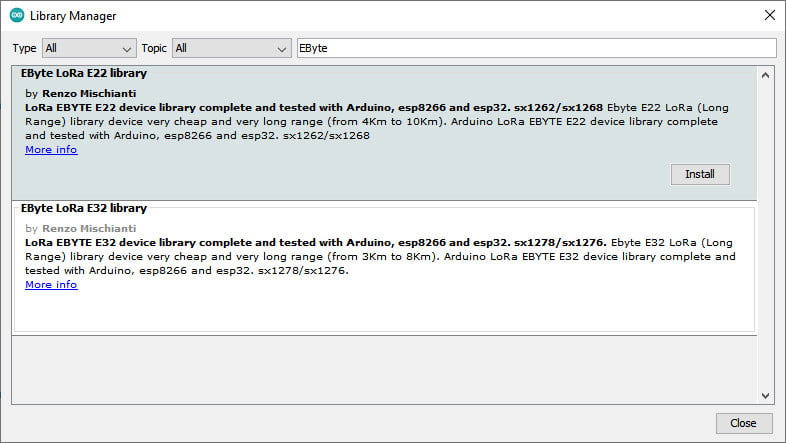
You can find my library here, and It’s available on Arduino IDE library manager.
To download.
Click the DOWNLOADS button in the top right corner, rename the uncompressed folder LoRa_E32.
Check that the LoRa_E32 folder contains LoRa_E32.cpp and LoRa_E32.h.
Place the LoRa_E32 library folder in your /libraries/ folder.
You may need to create the libraries subfolder if it’s your first library.
Restart the IDE.
Connection schemas for programming
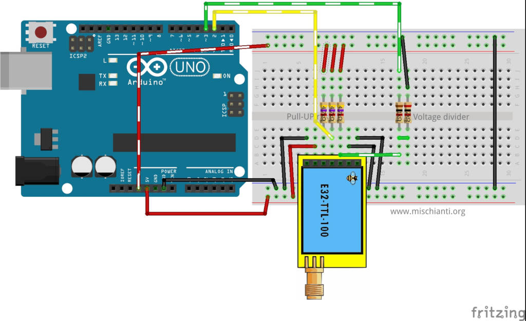
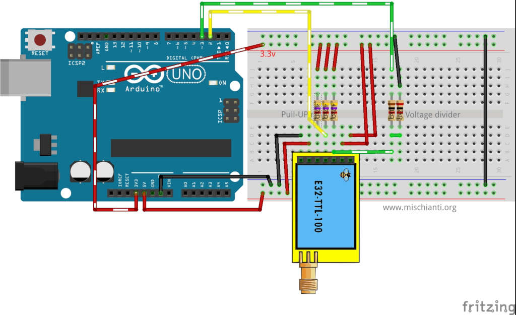
For the basic usage, we had used this configuration for Arduino. Still, you are working only in “Normal mode” in this configuration, and we will manage only the needed pin dynamic (RX, TX) to simplify the process.
Normal configuration (transparent)
| M0 | GND (Set normal mode) |
| M1 | GND (Set normal mode) |
| TX | PIN 2 (PullUP 4,7KΩ) |
| RX | PIN 3 (PullUP 4,7KΩ & Voltage divider) |
| AUX | Not connected |
| VCC | 3.3v |
| GND | GND |
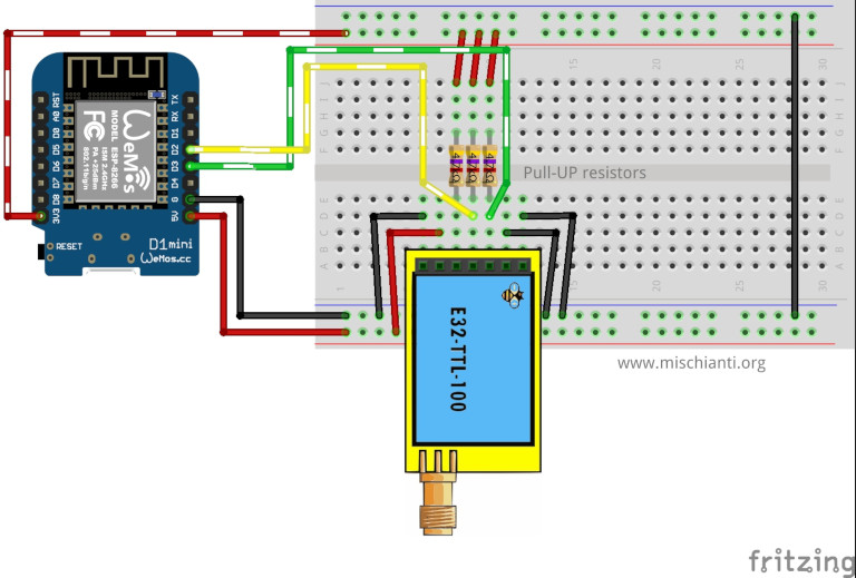
and this configuration for Wemos D1 mini:
| M0 | GND (Set normal mode) |
| M1 | GND (Set normal mode) |
| TX | PIN D2 (PullUP 4,7KΩ) |
| RX | PIN D3 (PullUP 4,7KΩ) |
| AUX | Not connected |
| VCC | 3.3v |
| GND | GND |
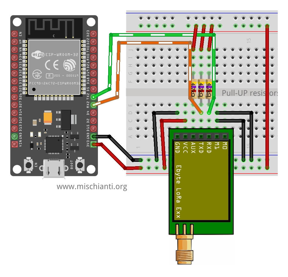
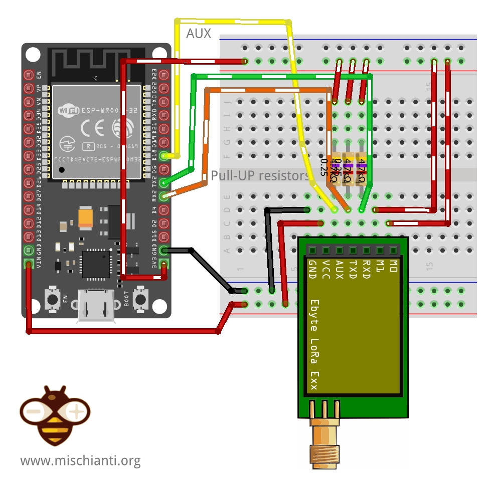
ESP-32:
| M0 | GND (Set normal mode) |
| M1 | GND (Set normal mode) |
| RX | TX2 (PullUP 4,7KΩ) |
| TX | RX2 (PullUP 4,7KΩ) |
| AUX | Not connected |
| VCC | 3.3v-5v |
| GND | GND |
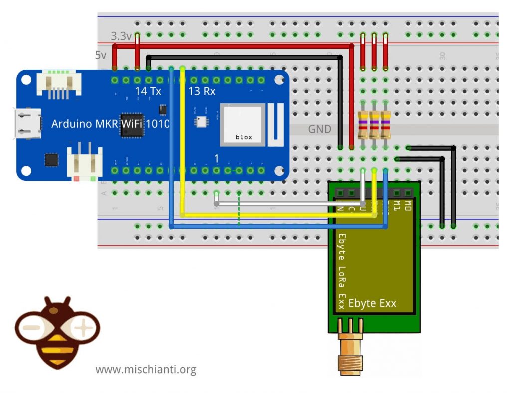
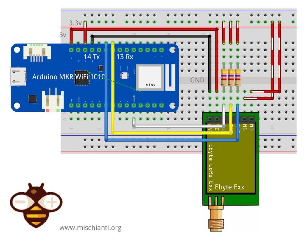
Arduino MKR WiFi 1010:
| M0 | GND (Set normal mode) |
| M1 | GND (Set normal mode) |
| TX | PIN 14 Tx (PullUP 4,7KΩ) |
| RX | PIN 13 Rx (PullUP 4,7KΩ) |
| AUX | PIN 1 (PullUP 4,7KΩ) |
| VCC | 5V |
| GND | GND |
Wiring for programming/sleep mode
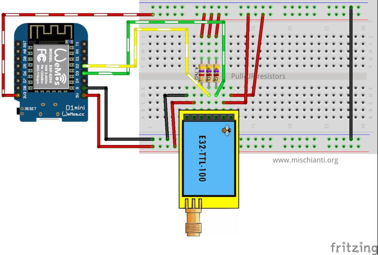
To configure It, you must set M0 and M1 to high (remember to use 3.3v).
But If you connect all pins, the library sets HIGH or LOW the pins as needed without a problem.
| M0 | VCC (Set programming/sleep mode) |
| M1 | VCC (Set programming/sleep mode) |
| TX | PIN D2 (PullUP 4,7KΩ) |
| RX | PIN D3 (PullUP 4,7KΩ) |
| AUX | Not connected |
| VCC | 3.3v |
| GND | GND |
| M0 | 3.3v (Set programming/sleep mode) |
| M1 | 3.3v (Set programming/sleep mode) |
| TX | PIN 2 (PullUP 4,7KΩ) |
| TX | PIN 3 (PullUP 4,7KΩ & Voltage divider) |
| AUX | Not connected |
| VCC | 3.3v |
| GND | GND |
| M0 | 3.3v (Set programming/sleep mode) |
| M1 | 3.3v (Set programming/sleep mode) |
| RX | TX2 (PullUP 4,7KΩ) |
| TX | RX2 (PullUP 4,7KΩ) |
| AUX | Not connected |
| VCC | 3.3v-5v |
| GND | GND |
| M0 | 3.3v (Set programming/sleep mode) |
| M1 | 3.3v (Set programming/sleep mode) |
| TX | PIN 14 Tx (PullUP 4,7KΩ) |
| RX | PIN 13 Rx (PullUP 4,7KΩ) |
| AUX | PIN 1 (PullUP 4,7KΩ) |
| VCC | 5V |
| GND | GND |
In this mode, you can manage the configuration of the device
Basic configuration option
| ADDH | High address byte of the module (the default 00H) | 00H-FFH |
| ADDL | Low address byte of the module (the default 00H) | 00H-FFH |
| SPED | Information about data rate parity bit and Air data rate | |
| CHAN | Communication channel(410M + CHAN*1M), default 17H (433MHz), valid only for 433MHz device | 00H-1FH |
| OPTION | Type of transmission, pull-up settings, wake-up time, FEC, Transmission power |
You can find configuration options in the Library article.
Get configuration
Arduino example sketch
/*
 * LoRa E32-TTL-100
 * Get configuration.
 * https://mischianti.org
 *
 * E32-TTL-100----- Arduino UNO
 * M0         ----- 3.3v
 * M1         ----- 3.3v
 * TX         ----- PIN 2 (PullUP)
 * RX         ----- PIN 3 (PullUP & Voltage divider)
 * AUX        ----- Not connected
 * VCC        ----- 3.3v/5v
 * GND        ----- GND
 *
 */
#include "Arduino.h"
#include "LoRa_E32.h"

LoRa_E32 e32ttl100(2, 3); // e32 TX e32 RX
void printParameters(struct Configuration configuration);
void printModuleInformation(struct ModuleInformation moduleInformation);

void setup() {
	Serial.begin(9600);
	delay(500);

	// Startup all pins and UART
	e32ttl100.begin();

	ResponseStructContainer c;
	c = e32ttl100.getConfiguration();
	// It's important get configuration pointer before all other operation
	Configuration configuration = *(Configuration*) c.data;
	Serial.println(c.status.getResponseDescription());
	Serial.println(c.status.code);

	printParameters(configuration);

	ResponseStructContainer cMi;
	cMi = e32ttl100.getModuleInformation();
	// It's important get information pointer before all other operation
	ModuleInformation mi = *(ModuleInformation*)cMi.data;

	Serial.println(cMi.status.getResponseDescription());
	Serial.println(cMi.status.code);

	printModuleInformation(mi);
    c.close();
}

void loop() {

}
void printParameters(struct Configuration configuration) {
	Serial.println("----------------------------------------");

	Serial.print(F("HEAD BIN: "));  Serial.print(configuration.HEAD, BIN);Serial.print(" ");Serial.print(configuration.HEAD, DEC);Serial.print(" ");Serial.println(configuration.HEAD, HEX);
	Serial.println(F(" "));
	Serial.print(F("AddH BIN: "));  Serial.println(configuration.ADDH, BIN);
	Serial.print(F("AddL BIN: "));  Serial.println(configuration.ADDL, BIN);
	Serial.print(F("Chan BIN: "));  Serial.print(configuration.CHAN, DEC); Serial.print(" -> "); Serial.println(configuration.getChannelDescription());
	Serial.println(F(" "));
	Serial.print(F("SpeedParityBit BIN    : "));  Serial.print(configuration.SPED.uartParity, BIN);Serial.print(" -> "); Serial.println(configuration.SPED.getUARTParityDescription());
	Serial.print(F("SpeedUARTDataRate BIN : "));  Serial.print(configuration.SPED.uartBaudRate, BIN);Serial.print(" -> "); Serial.println(configuration.SPED.getUARTBaudRate());
	Serial.print(F("SpeedAirDataRate BIN  : "));  Serial.print(configuration.SPED.airDataRate, BIN);Serial.print(" -> "); Serial.println(configuration.SPED.getAirDataRate());

	Serial.print(F("OptionTrans BIN       : "));  Serial.print(configuration.OPTION.fixedTransmission, BIN);Serial.print(" -> "); Serial.println(configuration.OPTION.getFixedTransmissionDescription());
	Serial.print(F("OptionPullup BIN      : "));  Serial.print(configuration.OPTION.ioDriveMode, BIN);Serial.print(" -> "); Serial.println(configuration.OPTION.getIODroveModeDescription());
	Serial.print(F("OptionWakeup BIN      : "));  Serial.print(configuration.OPTION.wirelessWakeupTime, BIN);Serial.print(" -> "); Serial.println(configuration.OPTION.getWirelessWakeUPTimeDescription());
	Serial.print(F("OptionFEC BIN         : "));  Serial.print(configuration.OPTION.fec, BIN);Serial.print(" -> "); Serial.println(configuration.OPTION.getFECDescription());
	Serial.print(F("OptionPower BIN       : "));  Serial.print(configuration.OPTION.transmissionPower, BIN);Serial.print(" -> "); Serial.println(configuration.OPTION.getTransmissionPowerDescription());

	Serial.println("----------------------------------------");

}
void printModuleInformation(struct ModuleInformation moduleInformation) {
	Serial.println("----------------------------------------");
	Serial.print(F("HEAD BIN: "));  Serial.print(moduleInformation.HEAD, BIN);Serial.print(" ");Serial.print(moduleInformation.HEAD, DEC);Serial.print(" ");Serial.println(moduleInformation.HEAD, HEX);

	Serial.print(F("Freq.: "));  Serial.println(moduleInformation.frequency, HEX);
	Serial.print(F("Version  : "));  Serial.println(moduleInformation.version, HEX);
	Serial.print(F("Features : "));  Serial.println(moduleInformation.features, HEX);
	Serial.println("----------------------------------------");

}
Here is the result of the sketch
Begin
Success
1
----------------------------------------
HEAD BIN: 11000000 192 C0

AddH BIN: 0
AddL BIN: 0
Chan BIN: 23 -> 433MHz

SpeedParityBit BIN    : 0 -> 8N1 (Default)
SpeedUARTDataRate BIN : 11 -> 9600bps (default)
SpeedAirDataRate BIN  : 10 -> 2.4kbps (default)
OptionTrans BIN       : 0 -> Transparent transmission (default)
OptionPullup BIN      : 1 -> TXD, RXD, AUX are push-pulls/pull-ups
OptionWakeup BIN      : 0 -> 250ms (default)
OptionFEC BIN         : 1 -> Turn on Forward Error Correction Switch (Default)
OptionPower BIN       : 0 -> 20dBm (Default)
----------------------------------------
Success
1
----------------------------------------
HEAD BIN: 11000011 195 C3
Model no.: 32
Version  : 44
Features : 14
----------------------------------------
If you change pins 2, 3 with D2, D3 you can do the same operation with your Wemos D1 or other esp8266/esp32.

To get the correct information, I add some #define to change the device type (same #define manage more other devices, I create only one for type for simplicity).
#define E32_TTL_100
#define E32_TTL_500
#define E32_TTL_1W
You can select only one of them. The parameter changes the Transmission power constant as described in the configuration schema.
In the same manner, you can select one reference frequences
#define FREQUENCY_433
#define FREQUENCY_170
#define FREQUENCY_470
#define FREQUENCY_868
#define FREQUENCY_915
You can choose only one of them. The parameter changes the reference frequencies only for display purposes,
Set configuration
Naturally, when you have a configuration you want to change It for your purpose, I think you can get the configuration from a device, modify what you want and set It.
Ricorda che il parametro saveType è fondamentale per mantenere le opzioni al riavvio del dispositivo, WRITE_CFG_PWR_DWN_LOSE naturalmente perderai le impostazioni con WRITE_CFG_PWR_DWN_SAVE non perderai le impostazioni.
Here is an Arduino sketch:
/*
 * LoRa E32-TTL-100
 * Get configuration.
 * https://mischianti.org
 *
 * E32-TTL-100----- Arduino UNO
 * M0         ----- 3.3v
 * M1         ----- 3.3v
 * TX         ----- PIN 2 (PullUP)
 * RX         ----- PIN 3 (PullUP & Voltage divider)
 * AUX        ----- Not connected
 * VCC        ----- 3.3v/5v
 * GND        ----- GND
 *
 */
#include "Arduino.h"
#include "LoRa_E32.h"

LoRa_E32 e32ttl100(2, 3); // e32 TX e32 RX
void printParameters(struct Configuration configuration);
void printModuleInformation(struct ModuleInformation moduleInformation);

void setup() {
	Serial.begin(9600);
	delay(500);

	// Startup all pins and UART
	e32ttl100.begin();

	ResponseStructContainer c;
	c = e32ttl100.getConfiguration();
	// It's important get configuration pointer before all other operation
	Configuration configuration = *(Configuration*) c.data;
	Serial.println(c.status.getResponseDescription());
	Serial.println(c.status.code);

	printParameters(configuration);
	configuration.ADDL = 0x0;
	configuration.ADDH = 0x1;
	configuration.CHAN = 0x19;

	configuration.OPTION.fec = FEC_0_OFF;
	configuration.OPTION.fixedTransmission = FT_TRANSPARENT_TRANSMISSION;
	configuration.OPTION.ioDriveMode = IO_D_MODE_PUSH_PULLS_PULL_UPS;
	configuration.OPTION.transmissionPower = POWER_17;
	configuration.OPTION.wirelessWakeupTime = WAKE_UP_1250;

	configuration.SPED.airDataRate = AIR_DATA_RATE_011_48;
	configuration.SPED.uartBaudRate = UART_BPS_115200;
	configuration.SPED.uartParity = MODE_00_8N1;

	// Set configuration changed and set to not hold the configuration
	ResponseStatus rs = e32ttl100.setConfiguration(configuration, WRITE_CFG_PWR_DWN_LOSE);
	Serial.println(rs.getResponseDescription());
	Serial.println(rs.code);
	printParameters(configuration);
    c.close();
}

void loop() {

}
void printParameters(struct Configuration configuration) {
	Serial.println("----------------------------------------");

	Serial.print(F("HEAD : "));  Serial.print(configuration.HEAD, BIN);Serial.print(" ");Serial.print(configuration.HEAD, DEC);Serial.print(" ");Serial.println(configuration.HEAD, HEX);
	Serial.println(F(" "));
	Serial.print(F("AddH : "));  Serial.println(configuration.ADDH, BIN);
	Serial.print(F("AddL : "));  Serial.println(configuration.ADDL, BIN);
	Serial.print(F("Chan : "));  Serial.print(configuration.CHAN, DEC); Serial.print(" -> "); Serial.println(configuration.getChannelDescription());
	Serial.println(F(" "));
	Serial.print(F("SpeedParityBit     : "));  Serial.print(configuration.SPED.uartParity, BIN);Serial.print(" -> "); Serial.println(configuration.SPED.getUARTParityDescription());
	Serial.print(F("SpeedUARTDatte  : "));  Serial.print(configuration.SPED.uartBaudRate, BIN);Serial.print(" -> "); Serial.println(configuration.SPED.getUARTBaudRate());
	Serial.print(F("SpeedAirDataRate   : "));  Serial.print(configuration.SPED.airDataRate, BIN);Serial.print(" -> "); Serial.println(configuration.SPED.getAirDataRate());

	Serial.print(F("OptionTrans        : "));  Serial.print(configuration.OPTION.fixedTransmission, BIN);Serial.print(" -> "); Serial.println(configuration.OPTION.getFixedTransmissionDescription());
	Serial.print(F("OptionPullup       : "));  Serial.print(configuration.OPTION.ioDriveMode, BIN);Serial.print(" -> "); Serial.println(configuration.OPTION.getIODroveModeDescription());
	Serial.print(F("OptionWakeup       : "));  Serial.print(configuration.OPTION.wirelessWakeupTime, BIN);Serial.print(" -> "); Serial.println(configuration.OPTION.getWirelessWakeUPTimeDescription());
	Serial.print(F("OptionFEC          : "));  Serial.print(configuration.OPTION.fec, BIN);Serial.print(" -> "); Serial.println(configuration.OPTION.getFECDescription());
	Serial.print(F("OptionPower        : "));  Serial.print(configuration.OPTION.transmissionPower, BIN);Serial.print(" -> "); Serial.println(configuration.OPTION.getTransmissionPowerDescription());

	Serial.println("----------------------------------------");

}
Here is the result on the console
Begin
Success
1
----------------------------------------
HEAD : 11000000 192 C0

AddH : 1
AddL : 0
Chan : 23 -> 433MHz

SpeedParityBit     : 0 -> 8N1 (Default)
SpeedUARTDatte  : 11 -> 9600bps (default)
SpeedAirDataRate   : 10 -> 2.4kbps (default)
OptionTrans        : 0 -> Transparent transmission (default)
OptionPullup       : 1 -> TXD, RXD, AUX are push-pulls/pull-ups
OptionWakeup       : 0 -> 250ms (default)
OptionFEC          : 1 -> Turn on Forward Error Correction Switch (Default)
OptionPower        : 0 -> 20dBm (Default)
----------------------------------------
Success
1
----------------------------------------
HEAD : 11000000 192 C0

AddH : 1
AddL : 0
Chan : 25 -> 435MHz

SpeedParityBit     : 0 -> 8N1 (Default)
SpeedUARTDatte  : 111 -> 115200bps
SpeedAirDataRate   : 11 -> 4.8kbps
OptionTrans        : 0 -> Transparent transmission (default)
OptionPullup       : 1 -> TXD, RXD, AUX are push-pulls/pull-ups
OptionWakeup       : 100 -> 1250ms
OptionFEC          : 0 -> Turn off Forward Error Correction Switch
OptionPower        : 1 -> 17dBm
----------------------------------------
The library is quite simple, but in the next chapter, we will test various device options.
Thanks
- LoRa E32 device for Arduino, esp32 or esp8266: settings and basic usage
- LoRa E32 device for Arduino, esp32 or esp8266: library
- LoRa E32 device for Arduino, esp32 or esp8266: configuration
- LoRa E32 device for Arduino, esp32 or esp8266: fixed transmission
- LoRa E32 device for Arduino, esp32 or esp8266: power saving and sending structured data
- LoRa E32 device for Arduino, esp32 or esp8266: WOR (wake on radio) microcontroller and Arduino shield
- LoRa E32 device for Arduino, esp32 or esp8266: WOR (wake on radio) microcontroller and WeMos D1 shield
- EByte LoRa E32 device for Arduino, esp32 or esp8266: WOR (wake on radio) and new ESP32 shield
- Ebyte LoRa E32 with STM32: WOR (wake on radio) and new STM32 shield
- Mischianti Arduino LoRa shield (Open source)
- Mischianti WeMos LoRa shield (Open source)
- Mischianti ESP32 DOIT DEV KIT v1 shield (Open source)
- STM32F1 Blue-Pill EByte LoRa E32, E22, and E220 Shield
- STM32F4 Black-Pill EByte LoRa E32, E22, and E220 Shield





Thank you.
Can i use Lora E32 (915T30D) 915MHZ with Arduino mega 2560 pro mini?
if yes how i can chang CAHN to 915 frequency because the max value of CAHN is 255 ?.
Hi feras,
the initial value of Channel Isn’t 0 but 915-23.
Bye Renzo
Hola Renzo,
Thank you for your excellent tutorial.
Is it possible to send a large message that exceeds 58 bytes (MAX_SIZE_TX_PACKET)?
Hi benzo,
No you can’t with e32, but e22 can send 240 bytes.
If you want can send multiple message to the buffer and read all in a single read.
Bye Renzo
Ciao Renzo,
1. The buffer is 512 bytes right? So I can send 8 or 9 packets and then read all them?
2. What if I have a message larger than 512 bytes?
Hi Benzo,
yes, you read all the buffer with e32ttl.receiveMessage() of you want read single message at time you must use e32ttl.receiveMessageUntil().
I think if the buffer is full you lost somme message.
Bye Renzo
I’m trying to use esp32. I have used pins D16 and D17 (RX and TX) as shown on the picture. The scketch does not work. Error message: invalid conversion from ‘int’ to ‘HardwareSerial*’ [-fpermissive]
Hi Janis,
open a forum topic and put your code there, so we can check what the issue is.
Bye Renzo
Hi Renzo, thank you for all the explanations and for the library that you have created. I am working with two E32 433T30D and when I try to set a transmissionPower diferent to 20, 17 or 10 the code do not compile. I am interested in use 30dbm to achive as long distance as possible and I can not set it like this. Would you know how to solve the problem?
Hi Victor,
Can you open a forum topic and paste your code?
Thanks Renzo
Hi, Mischanti Can we set the channel to 868MHz. Can You please tell us what channel we have to set in the configuration.
Hi Vid,
you can find the specification here.
you can define mhz before include.
if you have some context problem, put It directly in the statesNaming.h
But It’s needed only to read the current MHz in the getConfiguration, if you don’t set It, the device continues to work correctly.
Bye Renzo
Thank you.
Can i use Lora E32 (900T30D) 900MHZ with Arduino mega 2560 ?
if yes how i can chang CAHN to 868 frequency because the max value of CAHN is 255
Hi Vid,
every device have a starting number for channels
So to set 868 you must set
to read the correct MHz
But to set, you must put 6 as CAHN considering 862+6=868.
Bye Renzo
Hi, Mischanti. Would you like to help me to fix my connection problem?
I’m using an Arduino Nano and a Lora E32.
Firstly, I connected my USB-TLL to the Lora 32 and I could configure the Lora 32 via my computer.
Then, I connected my Arduino Nano to the Lora 32.
Lora 32 -> Arduino Nano
GND GND
VCC 5V
AUX
TX 5
RX 6
M1 7
M0 8
The output is always
“No response from device! (Check wiring)
12”
I tried many cases
1. My Arduino Nano was placed on the breadboard, the voltage of the pins was about 1.4V
2. My Arduino Nano was placed on the breadboard, the schematic was exactly like yours
3. Connected directly Arduino Nano pins to Lora e32 pins. Every pair of pins is a jumper
4. Connected directly M0 and M1 to 3.3V or 5V
5. Connected M0 and M1 to pins 7 and 8. I used digitalWrite(pin, LOW) before e32.begin()
6. Used all constructors of LoRa_E32, one by one (Some constructors couldn’t be used for ESP32)
I really don’t know which case to try. Your help is very appreciated.
Hi phuc,
you can follow the instruction of Arduino UNO with the same pin.
Here you can find the connection diagram Ebyte LoRa E32 device for Arduino, esp32 or esp8266: library – 2
Bye Renzo
Hi phuc,
I got the same problem as yours and tried 100 different connections.
I can transmit and see the module is transmitting by a receiver.
But the other diagrams for transmit and receive with the second do not work.
Also same as yours, I can not get the config. but I can get the config with comupter but not with Arduino.
I would appreciate it if you could write me if your problem is solved and how?
I am using Arduino Mega..
Iraj
Hi Iraj,
I receive al lot of messages like this. It’s a wiring or power supply problem.
Bye Renzo
Hello
I have E32-900t20D , how i can chang CHAN to 868 frequency
where should i put ” #define FREQUENCY_868″ in lora-E32.h or in my program
thank you
You can find a reply in other comments.
Bye Renzo
I see this is an older thread but just wanted to see if I could get an quick answer to my question. I have hooked up all pins/wires including M0 and M1 but there isn’t any mention of needing those set for digitalWrite or pinMode, so my question is do we need to set those pins or does the library take care of them. I did see that they get set to -1 in the h file but really no mention anywhere else. Oh one more question, addrH and addrL, are these little endian or big endian?
Thank you,
SomeWarez
Hi,
no, you don’t need to set It as input, the library do It for you.
addH and addL are Address HIGH and Address LOW, the most significant part and the less significant part of the address.
Bye Renzo
Sorry forgot to add that I get Success 1 when reading configuration data, but get Save mode returned not recognized! 11 when trying to save the configuration.
Any help is much appreciated.
Thank you
Hi,
Some people have this problem, usually when using an insufficient power supply.
Try to connect to a more efficient 5v power supply.
Bye Renzo
Hello!
I am getting error 12 when using an Arduino Mega, the wiring is correct because it works in an Arduino Uno. Is there something I have to do, for it to work on an Arduino Mega?
Sincerely,
Lucas
Hi Lucas,
Arduino Mega works well, better than Arduino UNO. I think you made a mistake.
Check also this.
Bye Renzo
Hello!
I made some adjustments, and it works now, thank you for the assistance.
Sincerely,
Lucas
Hi Lucas,
thanks for your feedback.
Bye Renzo
Hi Renzo! Sorry to bother you.
What would be the reason for the pull-ups in the pins? I am a little confused.
Sincerely,
Lucas
Hi Luca,
The pull-up resistor is used to stabilize the signal; in normal conditions, it may not seem important, but in long transmissions and on PCBs with some impedance, it can help achieve a clean transmission.
Bye Renzo